Hubbry Logo
Lever frameLever frameMain
Open search
Lever frame
Community hub
Lever frame
logo
8 pages, 0 posts
0 subscribers
Be the first to start a discussion here.
Lever frame
Lever frame
from Wikipedia

A mechanical lever frame inside the signal box at Knockcroghery in Ireland
Waterloo station A signalbox, LSWR (Howden, Boys' Book of Locomotives, 1907)

Mechanical railway signalling installations rely on lever frames for their operation to interlock the signals, track locks[1] and points to allow the safe operation of trains in the area the signals control. Usually located in the signal box, the levers are operated either by the signalman or the pointsman.[citation needed]

The world's largest lever frame is believed to have been in the Spencer Street No.1 signal box in Melbourne, Australia, which had 191 levers, but was decommissioned in 2008.[citation needed] The largest, currently operational, lever frame is located at Severn Bridge Junction in Shrewsbury, England, and has 180 levers; although most of them have now been taken out of use.[2]

Overview

[edit]
Lever frame of the signal box Hausen im Tal, Germany: the signals are operated by the red levers, black levers with Arabic numerals are for points and blue levers with Roman numerals are for track locks. The box on the right of the lever frame is used for manual block signalling; the smaller green levers are used for operating the route locks. The interlocking apparatus is in the box behind the levers.
A three-lever ground frame at Kyle of Lochalsh, released by Annett's key

The lever frame is located in the signal box, which can be a building at ground level or a tower, separated from or connected to an existing station building. Early lever frames were also built as ground frames next to the track, without any form of shelter and were usually operated by traincrew and not permanently staffed. Especially in England, lever frames with the pivot underneath the floor of the signal box were common.[3]: 122  This design's relatively short lever angle is a major disadvantage, as it requires more force to move the lever. Therefore, later, especially in Germany, lever frames with pivots inside the signaller's room were used, that allow for a lever angle of approximately 180°.[3]: 123 

By the movement of individual levers (or sometimes cranks),[3]: 123  signals, points, track locks, level crossing gates or barriers and sometimes navigable movable bridges over waterways are operated via wires and rods. The signaller chooses the correct combination of points, facing point locks and signals to operate, which will control the movement of each train through their area of control. The lever frame contains interlocking designed to ensure that the levers cannot be operated to create a conflicting train movement. Each interlocking installation is individual and unique to the location controlled. The interlocking may be achieved mechanically or by electric lever locks, or (more usually) a combination of both.[citation needed]

Variants

[edit]

Mechanical lever frames

[edit]
Truro Signal Box lever frame

A mechanical lever frame is designed to harness mechanical advantage to operate switch points, signals or both under the protection of the interlocking logic. The levers are connected to field appliances via solid pipes or taut wires such that the full travel of the lever will reliably cause full travel in the appliance. Each lever is engaged with the interlocking logic such that movement of the lever is only possible when all necessary conditions are met. The interlocking may be mechanical, electric (via solenoids) or both with the apparatus being mounted horizontally behind the lever frame[3]: 125  or vertically below it.

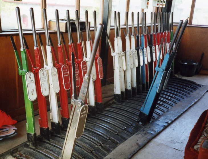
To assist the operator in determining their functions, each lever in a frame will generally be uniquely labelled, one common method being to number the levers in order from left to right. A lever's identification may be painted on its side or engraved on a badge or plate fitted either to the lever or behind it. This may be accompanied by a description of the lever's function. Usually, a large track diagram is positioned within easy view of the operator, which clearly shows each lever number adjacent to symbols representing the items of equipment that they operate. Levers are commonly coloured according to the type of equipment they control, the code of colours varying between different railway administrations. For example, in British practice, the following code generally applies: a red lever controls a stop signal or shunt signal, a yellow lever controls a distant signal, a black lever controls a set of points, a blue lever controls a facing point lock, and a white lever is spare. Brown levers are used to lock level crossing gates. Lever handles are usually of polished, unpainted steel, and signalmen operate them with a cloth to prevent rusting from the sweat on their hands.[4] In Germany, signal levers are red, whilst levers for points and track locks are usually blue, and route lock levers are green. Also, individual numbers and letters are used to indicate each individual item a lever operates in Germany as well.[3]: 126 

Some mechanical frames were combined with a set of electric levers or switches to more efficiently work electrically powered signals or other non-mechanically operated devices.[citation needed] Typically the switch points would be left under mechanical operation as the other devices used comparatively little electrical power and could be run off of batteries or a low capacity railroad-operated power system.[citation needed]

Power frames

[edit]
Everglades Junction signal box with its Westinghouse Brake & Signal Co. Ltd. Style 'L' Power Lever Frame

A power operated interlocking frame uses some form of power assist to operate switches, signals and other interlocking appliances in the field. The power can come from hydraulic, pneumatic or electric sources with direct acting or low voltage electric control.[3]: 250 

In hydraulic lever frames, moving the lever operates a hydraulic valve rather than wires and rods. To prevent accidents, operating a set of points requires pulling the actual lever for the points and a secondary check lever. The points are then moved by a hydraulic motor. This type of power frame has the disadvantage of a relatively low distance between points and signal box (approximately 200–250 m) and a slow operating speed. It was common in Italy and France only.[3]: 250  Pneumatic lever frames have an operating principle that is related to that of hydraulic lever frames, however, instead of a hydraulic liquid, compressed air is used. The two types also share the same disadvantages such as pressurized tubing having to run directly between the field appliance and the lever frame. Electric control of a hydraulic or pneumatic actuator in the field was far simpler and more reliable, allowing for a greater distance between signal box and points. Whilst first being common in the United States due to work by the Union Switch & Signal corporation (a division of Westinghouse Air Brake Company), this system was later used in the United Kingdom and other Commonwealth nations where the Westinghouse Air Brake Company had a presence.[3]: 251 

In Austria, Siemens & Halske built a fully electric power frame in 1894, which does not rely on compressed air. Instead, electric motors move the points. Later, this system was also used in Germany.[3]: 252  In the United States the Taylor Signal Corporation, later merged into General Railway Signal developed an electrically powered interlocking system that made use of mechanical slides to engage traditional mechanical locking. Union Switch and Signal later modified their electro-pneumatic system to all-electric as early as 1896.[citation needed]

A major issue with power frames was ensuring that the position of the levers on the frame correctly represented the position of the switch or other appliance in the field. Unlike a mechanical linkage, pneumatic or hydraulic lines could leak and cause points to drift out of correspondence with disastrous consequences. The Taylor/GRS electric power frame system used a feature called "dynamic indication" where the counter-electromotive force generated when the electric motor reached the limit of travel would signal the interlocking logic that the points had finished moving, but not the position of the points on an ongoing basis.[5] This and other open loop systems designed in the 19th and early 20th centuries to save on costly relays, were replaced by closed loop systems after a number of accidents. In North America this is known as "Switch-Signal" protection and any change in the position of a field appliance will immediately set the electric signals controlled by a power frame to danger.[6]

[edit]

See also

[edit]

References

[edit]
[edit]
Revisions and contributorsEdit on WikipediaRead on Wikipedia
from Grokipedia
A lever frame is a mechanical interlocking apparatus installed in railway signal boxes, consisting of a bank of levers that control the operation of signals and points (switches) to direct and safeguard movements on a railway line. It functions by physically linking the levers through rods, wires, and locking mechanisms to prevent the signalman from setting conflicting routes, such as clearing a signal for one while points are set for a diverging path that could cause a collision. This system ensures compliance with safety principles, allowing only compatible combinations of signals and points to be operated simultaneously. The lever frame emerged in the mid-19th century as railways expanded rapidly, necessitating centralized and reliable signaling to manage increasing traffic. In 1856, John Saxby patented an device for simultaneously working points and signals, laying the foundation for the modern lever frame. Saxby later collaborated with John Farmer, forming a partnership in 1863. By the 1870s, the introduction of fully lever frames revolutionized signaling practices, particularly on British railways, by consolidating all controls into a single frame within a dedicated signal box and transforming the role of trackside staff into professional signalmen. This development integrated with the block signaling system, which divided tracks into sections to maintain safe distances between trains, significantly reducing accidents during the . Operationally, lever frames feature color-coded levers to denote their function: red for stop signals, yellow for distant signals, black for points, blue for point locks, and other colors for auxiliary controls like ground frame locks or spare functions. When a signalman pulls or pushes a through its full , it transmits motion via wire ropes or rods to the trackside equipment, with the frame's or stud interlocking system (invented by Stevens & Sons and widely adopted after their expired) physically blocking incompatible levers. Frames vary in size from small ground frames with a few levers for local control to large installations exceeding 100 levers in major junctions, housed in elevated signal boxes for visibility. Over time, numerous designs proliferated among British railway companies, including those by Saxby & Farmer, McKenzie & Holland, and in-house Great Western Railway frames, each refining for efficiency and durability. By the early , mechanical lever frames had become standard, with British Railways operating over 10,000 signal boxes by 1948, though electrification and power signaling began supplanting them from the 1900s onward. Today, while largely preserved on heritage lines like the , lever frames represent a pinnacle of 19th-century ingenuity in railway safety.

History

Origins and invention

The lever frame emerged as a pivotal in signaling during the mid-19th century, primarily to address the escalating risks of train collisions at junctions amid Britain's rapid rail expansion. Following the of the , which spurred extensive track construction but overwhelmed rudimentary manual signaling methods reliant on individual policemen operating flags or semaphores, accidents surged due to and inadequate coordination of points and signals. This context motivated engineers to develop centralized mechanical systems for safer control, transforming scattered signal operations into unified, mechanisms. John Saxby, a carpenter employed by , and South Coast Railway, conceived the lever frame around this period, patenting his design in as "a mode of working simultaneously the points and signals of railways at junctions to prevent accidents." His invention introduced a frame of levers that mechanically linked signal and point operations from a single location, incorporating basic to ensure conflicting routes could not be set simultaneously. The emphasized prevention of disasters from improper point switching during train movements, building on earlier wire-based systems but advancing toward more reliable rigid rod connections. Saxby's initial prototype was installed the same year at Bricklayers Arms Junction on the South Eastern Railway near , featuring eight signals and wire-and-pulley linkages to operate points and signals over distances up to 300 yards. This setup marked the first practical application of centralized , evolving from flexible wire systems—susceptible to weather and tension issues—toward sturdier frames with horizontal rods for greater precision and durability in complex junctions. Contemporary inventors like Edward Tyer complemented Saxby's mechanical advances with patents for signal telegraphs in 1852 and 1854, enabling electrical coordination that integrated with emerging lever frames to enhance block signaling on busy lines. Saxby's 1856 interlocking patent laid the foundational framework, influencing subsequent designs and setting the stage for widespread adoption in preventing route conflicts.

Development and adoption in railways

The adoption of lever frames in British railways accelerated during the , driven by the need for safer signalling systems amid growing traffic volumes. Saxby & Farmer's rocker locking mechanism, patented and introduced in 1871, represented a significant advancement in design, allowing centralized control of signals and points from a single frame. This system gained rapid acceptance, with installations such as the hook-interlocking frame at in 1861 evolving into more refined versions by the decade's end, establishing Saxby & Farmer as the dominant manufacturer by 1880. Regulatory mandates further propelled standardization, as the British Board of Trade's Regulation of Railways Act of 1874 required interlocking of points and signals on all new passenger lines to prevent conflicting movements. This applied prospectively to installations after the Act's passage, influencing the widespread replacement of older, non-interlocked frames and promoting uniform designs across major railways like the London & North Western and Great Western. By the 1880s, lever frames had become integral to British railway operations, with over 1,000 signal boxes equipped by the turn of the century. The technology spread internationally in the late 19th century, reaching through firms like , which adapted mechanical principles for German networks in the 1890s, culminating in their fully electric power frame installation in by 1894. In , the Pennsylvania Railroad adopted interlocking lever frames during the 1880s as part of broader safety enhancements, with early examples like the installations reflecting British influences. Technological refinements included the introduction of tappet locking in the early 1890s by manufacturers such as McKenzie & Holland, which simplified mechanical interactions and improved reliability over earlier rocker systems. Electric detection mechanisms, integrating circuit-based point and signal verification, emerged in the 1900s, enhancing safety by confirming lever operations remotely. Global adoption extended to colonial networks, with installing mechanical lever frames from the 1870s onward, often using British designs like those from Saxby & Farmer to manage expanding lines in regions such as Bombay and Calcutta. In , McKenzie & Holland established a manufacturing facility in in 1880, facilitating widespread installations on Victorian and railways by the mid-1880s, including early tappet-equipped frames for junction control. These developments underscored the lever frame's role in enabling complex route management across diverse geographies.

Design and Components

Frame structure and materials

Lever frames form the structural backbone of mechanical railway signalling systems, typically installed within dedicated signal boxes to support and align the operating s in a straight line. The overall design scales with the complexity of the track layout, accommodating anywhere from a few to over 100 levers, with the frame's determined by standard lever spacing of 4 to 5 inches between centers. For instance, a frame with 57 levers measures approximately 4.42 meters in , highlighting how larger installations could extend to 6 meters or more for extensive junctions. These frames are usually floor-mounted at waist height for ergonomic operation, though smaller ground frames might be elevated on wooden platforms. Early lever frames, dating from the 1860s to the early 1900s, were predominantly constructed using robust hardwoods such as or for the main frame and protective casing, chosen for their resistance to and long-term in the damp, operational environments of signal boxes. was commonly employed for critical components like locking castings and tappets, providing the necessary strength for mechanisms, while metal—often or —was used for levers and pivots to ensure smooth movement. By the , designs began incorporating more elements in the frame structure and supports, enhancing resistance and overall rigidity, as seen in installations with oiled casings reinforced by components. This evolution reflected broader advancements in , prioritizing safety and maintenance in increasingly complex networks. Layout variations included end-on arrangements, where the frame aligned parallel to the track for optimal visibility through box windows, and side-on setups perpendicular to the line, common in platform-end boxes to suit space constraints. Supporting the levers' operation, frames integrated pulleys, wire runs, and rod connections to external equipment; steel pipe or channel rodding transmitted pulls over distances up to 350 yards, while wire systems extended to 600 yards, often routed through underground pipes or above-ground supports to minimize interference. These elements ensured reliable mechanical transmission from the frame to distant signals and points.

Levers, rods, and locking mechanisms

In lever frames, the primary operating components are the levers themselves, which are arranged in a straight line and numbered consecutively from the signalman's left. Signal levers, colored for stop signals and for distant signals, control or disc signals to indicate track clearance for ; they operate with a pull of approximately 300 mm. Point levers, usually black, manage track switches (points) with a pull of approximately 200 mm to align routes; facing point lock (FPL) levers, often blue, secure points against unintended movement during passage on facing routes. Levers for signals and points are interspersed in numerical order according to the track layout. Color coding varied by railway company but followed conventions such as for stop signals, for distant signals, black for points, and blue for locks on the Great Western Railway from 1894 and the North Eastern Railway from 1902. Transmission from the lever frame to distant signals and points occurs via rod and wire systems, with rigid used for short distances up to about 300 feet where straight-line runs minimize . These , typically 30 mm in with roller guides spaced every 2 meters, connect directly to cranks at changes in direction but are limited by transmission losses over longer spans. For extended runs beyond 300 feet, flexible wire systems—either single-wire (8-10 SWG) or double-wire loops—provide greater reach, up to 500 meters or more, using a pull-push mechanism anchored near the frame. Both systems incorporate compensation for : use sliding joints or compensator cranks at intervals of 36.5 meters, while wires employ cabin adjusters to maintain tension. Locking mechanisms within the frame ensure safety by physically preventing conflicting lever movements, primarily through mechanical bolt-and- designs that interlock s via sliding tappets and bolts. The tappet system, invented by Stevens & Sons around 1870 and becoming nearly universal, uses spring-loaded bars and dogs to block unauthorized pulls, replacing earlier hook-locking methods for greater reliability. Specific implementations include Saxby & Farmer's vertical lock, featuring a vertically oriented grid of lever and locking bars that interact along axes to enforce route conditions, and McKenzie & Holland's horizontal lock from their 1873 patent, where cams and rotating locks drop heels to secure levers normal when others are reversed. Indicators on the levers provide visual and status feedback to the signalman. Lever badges, often brass or cast-iron plates fixed near the lever base or top, display the lever number, function (e.g., "signal" or "points"), and associated pull sequence, as standardized in designs by Saxby & Farmer and Stevens & Sons. Counterweights at the lever ends balance the mechanism for easier operation, while electrical repeaters—wired indicators in the frame or cabin—relay remote positions of signals and points to confirm alignment.

Operation

Manual operation process

The manual operation of a lever frame requires the signalman to physically manipulate a series of levers arranged in a straight line within the signal box, coordinating movements to control signals and points for safe routing. The typically begins with the signalman observing an approaching via the box window or indicators and selecting the desired route based on train orders or block system communications. To set the route, the signalman first pulls the relevant point levers to align the track—leaving them in the normal position for the main line or reversing them for a siding—before pulling the corresponding signal levers to clear the path, starting with the home signal at the box's entry. This sequence ensures points are correctly positioned before signals can be cleared, with the entire process for a single route often taking several seconds depending on frame size and conditions. Route setting involves combining signal and point levers to establish complete paths, such as directing a onto the main line by maintaining point levers normal and pulling the main line signal lever, or diverting freight to a siding by reversing the point lever and pulling the associated distant or shunt signal. In cases requiring temporary overrides, such as for shunting or non-standard movements, release levers may be pulled to temporarily disengage certain locks, allowing restricted operations while adhering to safety protocols. The mechanical integrated into the frame enforces this combination, preventing the signalman from pulling a signal lever unless the points are correctly set for that route. Feedback during operation comes primarily from the frame's mechanical components, where successful pulls produce distinct auditory clicks as locks engage or tappets slide into position, confirming the route is set. Visual indicators, such as labels on the levers or a track illuminated by the lever positions, provide confirmation of the setup. If a pull fails due to a lock—indicating conflicting routes, occupied tracks, or incomplete prior settings—the signalman encounters physical resistance and must identify and reverse the obstructing levers before retrying, often consulting the frame's locking chart for guidance. These mechanisms ensure error handling is immediate and prevents unsafe configurations. As part of daily routines, signalmen perform frame balancing by adjusting rod and wire tensions to maintain even pull effort across levers, oil the , bearings, and to reduce and prevent wear, and keep detailed logs in the train register book recording all movements, times, and any irregularities for operational audits and safety investigations. These tasks, typically conducted during shift handovers or quiet periods, help sustain reliable performance over long shifts.

Interlocking and safety features

The principle of in lever frames refers to a mechanical arrangement of levers, rods, and locking elements that prevents conflicting train movements by ensuring points (switches) are correctly set and locked before any signal can be cleared to permit a route. This system enforces that signals remain in their normal position—indicating danger—until the entire route ahead is verified as safe, thereby avoiding errors such as setting a signal for a route where points are misaligned. The mechanism typically involves tappets or catches on the levers that physically block unauthorized movements, allowing the signalman to pull only compatible levers in a specific sequence. Lever frames incorporate various types of locks to enhance safety, including physical bolt locks for securing facing points against unintended movement and ensuring detection of route alignment. Electrical locks, introduced in the late 19th century, supplemented mechanical systems with track circuits—electrical devices that detect train occupancy on sections of track by completing or breaking a low-voltage circuit through the rails. Invented by William Robinson in 1872 and widely adopted in the early 1900s, track circuits provided fail-safe operation by defaulting to a "safe" state where signals remain at danger if occupancy is detected or if the circuit fails due to breakage, dirt, or shunting. This fail-safe design principle ensures that any malfunction or incomplete setup results in the system locking into the safest configuration, preventing authorization of unsafe movements. Backlocking and releasable locks further refine safety by preventing premature reversal of routes during operations. Backlocking mechanically locks the point levers in their set position when a signal lever is reversed (cleared), preventing any alteration to the points until the signal lever is returned to its normal (danger) position, thereby maintaining the route's integrity during the train's passage. Releasable locks, often used for auxiliary functions like shunting, allow temporary override under controlled conditions but require positive action to disengage, ensuring they cannot be inadvertently left unsecured. These features align with established by the Regulation of Railways Act 1873, which mandated for facing points to reduce collision risks, as enforced by the .

Types and Variants

Mechanical lever frames

Mechanical lever frames formed the cornerstone of traditional railway signalling systems, relying exclusively on manual operation through interconnected , rods, and wires to control points, signals, and derails without any electrical components. These frames transmitted mechanical directly from the signalman's levers to trackside equipment, using rigid rodding—typically tubes or channels—for points and flexible wire ropes for distant signals, enabling precise route setting in localized areas. mechanisms, often or rocker types, physically prevented the reversal of levers that could create conflicting movements, ensuring operation through mechanical logic alone. Such systems were ideally suited to small and medium-sized stations, where frames commonly featured up to 50 levers to manage a handful of routes and sidings efficiently. The advantages of these fully manual setups lay in their simplicity and robustness, particularly in remote or rural locations lacking reliable , where they provided consistent performance without dependence on power supplies or complex wiring. This inherent reliability minimized downtime from electrical faults, making them a staple in less-trafficked lines. However, limitations were evident in their labor-intensive nature, requiring significant physical effort from to operate and reset levers, especially under repetitive use. Transmission distances were also constrained, with rodding effective up to approximately 1/4 mile (440 yards) before friction and alignment issues necessitated intermediate relays or pulleys, confining their application to compact yard layouts rather than expansive networks. Notable examples highlight their historical dominance and engineering scale. The Junction signal box near , , features the world's largest operational mechanical lever frame, comprising 180 levers installed in 1903 by the Great Western Railway, which controls a dense web of converging lines and remains in daily use for over 280 trains. In contrast, smaller frames, such as the 52-lever setup at Foxfield on the , illustrate typical applications in operations. Maintenance practices emphasized periodic checks to preserve integrity; annual inspections by signalling engineers involved verifying lever alignment, rod adjustments for via compensators, and full locking tests to detect wear or binding, ensuring compliance with safety standards. Post-World War II, mechanical lever frames began a marked decline as railway traffic surged, rendering their manual operation and spatial constraints impractical for busy junctions; and power-assisted systems offered greater capacity and reduced manpower needs, leading to widespread replacement. The population of mechanical signal boxes in plummeted from about in to fewer than 500 today, preserving only heritage or low-volume routes.

Electro-mechanical and power frames

Electro-mechanical lever frames integrate electrical components with traditional mechanical to operate railway points, signals, and derails, minimizing the length of mechanical rod runs and enabling more precise control through electric point motors and track circuits that detect occupancy and enforce safety. Developed in the late , these systems marked a significant advancement by allowing signalmen to control distant functions without extensive physical linkages, reducing wear and installation costs in expansive networks. Early examples include the installations by the General Railway Signal Company (GRS), which deployed the first electric machine in 1891 on the & Southwestern Railway, evolving from electro-pneumatic predecessors to fully electric designs by the early 1900s. In the United States, electro-pneumatic systems emerged in the , with GRS advancing them from its formation in 1904 onward using low-pressure air mechanisms for signals, offering advantages over pure by avoiding freezing issues and requiring less maintenance—operational costs as low as $4 per month compared to $400 for pneumatic alternatives. These frames supported remote operations up to 6,000 feet, with polarized relays providing cross-protection against unauthorized lever pulls. A key feature of electro-mechanical frames is the use of dynamic indication, where from electric motors confirms the position of points and signals, providing immediate feedback to the signalman and preventing conflicting routes. Westinghouse power frames, introduced around 1906 for London's Underground, exemplified this integration with compact electro-mechanical levers that housed mechanical alongside electrical releases, facilitating efficient operation in space-constrained urban environments. By 1913, GRS had installed 440 such plants across 83 North American railways, totaling over 21,370 levers, demonstrating widespread adoption for junctions and yards where mechanical limitations were prohibitive. Power frames further enhance this by incorporating pneumatic or electro-pneumatic assistance, where lever movements trigger (typically at 60 psi) or valves to power switches and signals, often combined with electrical controls for hybrid efficiency. Innovations in lever design distinguished these systems, such as one-motion levers for direct operation versus two-motion levers requiring a preliminary release for added verification, particularly in high-traffic settings. The London and North Western Railway's installation in 1908/9 at Manchester London Road station (now ), later operated by the London, Midland and Scottish Railway, featured an all-electric frame with 244 levers under the Crewe all-electric system, controlling color-light signals and points across a major terminal with integrated route locking. This setup highlighted scalability for large yards, where power assistance allowed signalmen to manage complex interlockings without physical strain. In , standards from the American Railway Engineering and Maintenance-of-Way Association (AREMA) guide the design and implementation of power frames, emphasizing reliable power supplies (e.g., 110V DC batteries with automatic charging) and interlocking protocols to ensure compatibility in modern . These guidelines promote capabilities and modular components, enabling expansion in freight yards while maintaining safety through features like electromagnetic release locking. Overall, electro-mechanical and power frames transitioned railway signaling toward greater , supporting denser traffic and longer control spans compared to unassisted mechanical types.

Modern Usage and Decline

Current applications

In the , approximately 680 mechanical signal boxes remain operational as of 2024, primarily on heritage railways and low-traffic lines managed by . These installations are concentrated on preserved routes such as the , where examples include the 30-lever frame at Arley signal box, which controls signals and points for tourist operations. In contrast, power-operated lever frames are rare globally; in , they persist in limited numbers on secondary lines but are increasingly replaced by electronic systems, as seen in the 2024 decommissioning at a historical yard. Similarly, maintains only a handful of such frames, including the Westinghouse miniature lever power frame at Barton, one of the last operational examples worldwide. Lever frames continue in hybrid configurations interfaced with contemporary signaling technologies, particularly in remote areas. In , mechanical lever frames integrate with Radio Electronic Token Block (RETB) systems on lines like the Far North route, where ground frames release tokens electronically while retaining manual point and signal control for single-track sections. Under EU Technical Specifications for (TSI), particularly the Control-Command and Signalling (CCS) TSI, mechanical systems receive regulatory allowances for legacy infrastructure on non-high-speed networks, permitting their use alongside modern ETCS upgrades provided safety equivalence is demonstrated. These frames find ongoing application in low-traffic rural and heritage settings due to their cost-effectiveness compared to full digital overhauls, avoiding high capital expenditures for lines with infrequent services. On preserved railways, they facilitate hands-on training for signalmen, where volunteers learn principles, lever sequencing, and safety protocols through practical operation, as practiced on routes like the . Recent enhancements to surviving frames include digital monitoring add-ons to improve visibility and reduce maintenance errors.

Preservation and legacy

Efforts to preserve lever frames have focused on documenting and maintaining these mechanical signaling systems as key artifacts of railway history, particularly in the where they originated and proliferated. Organizations such as the Signalling Record Society maintain detailed registers of signal boxes, including mechanical lever frames, to track their locations and conditions, supporting heritage railways and museums in safeguarding examples from the peak era when over 10,000 signal boxes operated nationwide in the 1940s. The in houses several operational lever frames, including a restored tumbler frame used for public demonstrations, highlighting their role in educating visitors on historical train control methods. Restoration projects underscore the dedication to reviving these intricate devices despite logistical hurdles. A prominent example is the Signalling School layout, featuring a 1912 mechanical lever frame originally used for training until 1995; it was relocated to the in the 2010s and meticulously restored to working order, involving repairs to mechanisms and integration with modern simulation for interactive exhibits. Similar initiatives face challenges in sourcing obsolete components, such as custom tappets and locking bars, often requiring fabrication from original blueprints or salvaged parts to maintain authenticity while ensuring safe operation. The legacy of lever frames extends beyond physical preservation, influencing contemporary railway safety systems through foundational interlocking principles that prevent conflicting movements—concepts now encoded in software for advanced technologies like (CBTC). These early mechanical designs established the bedrock of route-setting logic, which persists in digital to enhance capacity and reliability on modern networks. Additionally, preserved frames offer significant educational value, allowing hands-on exploration of signaling from manual operations to automated systems, as seen in demonstrations that illustrate historical accident prevention strategies. Globally, preservation efforts mirror those in the , with institutions like the featuring interactive signaling exhibits that recreate lever-based controls to interpret America's rail heritage. The decline of lever frames has been dramatic; from approximately 10,000 in use across the in the 1940s, fewer than 500 mechanical boxes remained operational by the early , with around 680 as of 2024 and over 90% replaced by panel-based or centralized systems to meet growing traffic demands, with most planned for decommissioning by 2040.

References

Add your contribution
Related Hubs
User Avatar
No comments yet.