Community hub
Light beam
View on WikipediaThis article needs additional citations for verification. (April 2010) |


A light beam or beam of light is a directional projection of light energy radiating from a light source. Sunlight forms a light beam (a sunbeam) when filtered through media such as clouds, foliage, or windows. To artificially produce a light beam, a lamp and a parabolic reflector is used in many lighting devices such as spotlights, car headlights, PAR Cans, and LED housings. Light from certain types of laser has the smallest possible beam divergence.
Visible light beams
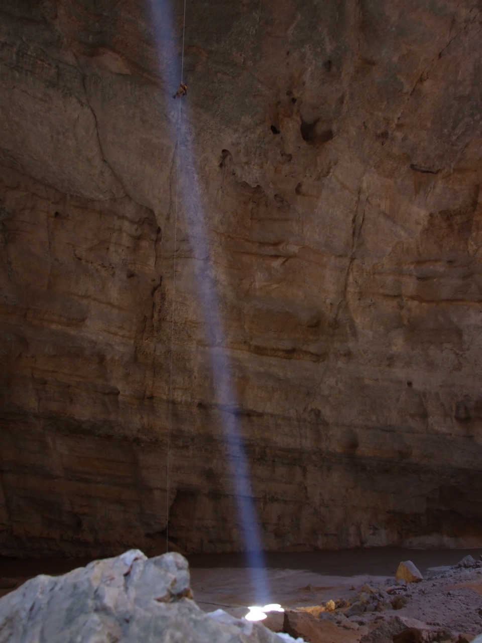
[edit]From the side, a beam of light is only visible if part of the light is scattered by objects: tiny particles like dust, water droplets (mist, fog, rain), hail, snow, or smoke, or larger objects such as birds. If there are many objects in the light path, then it appears as a continuous beam, but if there are only a few objects, then the light is visible as a few individual bright points. In any case, this scattering of light from a beam, and the resultant visibility of a light beam from the side, is known as the Tyndall effect.
Visibility from the side as side effect
[edit]- Flashlight (UK 'Torch'), beam directed by hand
- Headlight, forward beam; the lamp is mounted in a vehicle, or on the forehead of a person, e.g. built into a helmet
- Lighthouse, beam sweeping around horizontally
- Searchlight, beam directed at something
Visibility from the side as purpose
[edit]For the purpose of visibility of light beams from the side, sometimes a haze machine or fog machine is used. The difference between the two is that the fog itself is also a visual effect.


- Laser lighting display- Laser beams are often used for visual effects, often in combination with music.
- Searchlights are often used in advertising, for instance by automobile dealers; the beam of light is visible over a large area, and (at least in theory) interested persons can find the dealer or store by following the beam to its source. This also used to be done for movie premieres; the waving searchlight beams are still to be seen as a design element in the logo of the 20th Century Fox movie studio.
Other applications
[edit]See also
[edit]- Beam diameter
- Collimated beam
- Crepuscular rays
- Light pillar, atmospheric optical phenomena
- Pencil beam
- Ray (optics)
- Relativistic beaming
References
[edit]External links
[edit]Light beam
View on GrokipediaFundamentals
Definition and Basic Properties
A light beam is a directional projection of light energy radiating from a source, propagating essentially in one direction while maintaining a limited spatial extension perpendicular to that direction.[1] It consists of photons, the fundamental quanta of electromagnetic radiation, traveling along a specific path.[9] Unlike diffuse light that spreads omnidirectionally, a beam's directionality allows it to concentrate energy over distance, often achieved through collimation to minimize divergence.[1] The basic properties of a light beam include its wavelength, which determines its color in the visible spectrum and ranges from approximately 400 to 700 nanometers for human perception, though beams can extend into ultraviolet (below 400 nm) and infrared (above 700 nm) regions.[10] Intensity distribution refers to the variation of light energy across the beam's cross-section, typically higher at the center and tapering outward.[1] This directionality fundamentally distinguishes beams from scattered or ambient light, enabling applications requiring focused illumination.[1] Early conceptualizations of light beams trace back to 17th-century optics, where Isaac Newton described light rays as streams of corpuscles—tiny particles—propagating in straight lines, laying groundwork for understanding directional light propagation.[11] Contemporaneously, Christiaan Huygens proposed a wave theory in which rays of light also travel linearly, influenced by secondary wavelets from each point on a wavefront, serving as precursors to modern beam ideas.[12] For visible light beams, luminous flux quantifies the total perceived power output in lumens (lm), accounting for human eye sensitivity.[13] Irradiance measures the power per unit area incident on a surface, expressed in watts per square meter (W/m²), providing a key metric for beam energy density.[14]Beam Formation and Propagation
Light beams are formed through the emission of light from a source followed by optical manipulation to achieve a directed, parallel stream of rays. Point sources such as light-emitting diodes (LEDs) produce light via electroluminescence in semiconductor materials, where electrons recombine with holes to emit photons in a roughly isotropic manner.[15] Arc lamps, on the other hand, generate light through an electric discharge between electrodes, creating a high-temperature plasma that emits a broad spectrum via thermal radiation and atomic transitions.[16] To form a beam, this emitted light is collimated using lenses or apertures, which redirect diverging rays into a parallel bundle; for instance, placing a point source at the focal point of a converging lens produces a collimated output where rays are parallel.[17] Apertures play a critical role in defining beam boundaries by limiting the spatial extent of the light, suppressing unwanted diffraction edges and shaping the intensity profile.[18] In propagation, light beams follow straight-line paths in a vacuum or uniform medium according to Fermat's principle, which states that light travels the path of least time between two points, equivalent to the shortest optical path length in homogeneous media.[19] However, wave nature introduces diffraction, causing beams to spread transversely even in free space; this angular spreading arises from the interference of wavefronts at the beam's edges, with the minimum divergence limited by the aperture size or source dimension.[20] When entering a different medium, beams refract according to Snell's law, $ n_1 \sin \theta_1 = n_2 \sin \theta_2 $, where $ n $ is the refractive index and $ \theta $ the angle from the normal, bending the propagation direction due to the speed change in the medium.[21] Environmental interactions during propagation lead to beam attenuation through absorption and scattering. Absorption occurs when photons are captured by material particles, converting light energy into heat or chemical reactions, following Beer's law where intensity $ I(z) = I_0 e^{-\alpha z} $, with $ \alpha $ the absorption coefficient and $ z $ the distance.[22] Scattering redirects light in various directions: Rayleigh scattering dominates for particles much smaller than the wavelength ($ d \ll \lambda $), with cross-section proportional to $ 1/\lambda^4 d \approx \lambda $), producing forward-directed scattering with less wavelength dependence, as seen in white clouds.[23] These processes collectively reduce beam intensity over distance, with total attenuation given by $ \beta = \alpha + \sigma_s $, where $ \sigma_s $ is the scattering coefficient.[24] A key quantitative aspect of beam propagation is divergence, particularly for Gaussian-profile beams, which approximate the diffraction-limited case and influence spreading behavior. The half-angle divergence $ \theta $ far from the waist is approximated as $ \theta \approx \frac{\lambda}{\pi w_0} $, where $ \lambda $ is the wavelength and $ w_0 $ the beam waist radius at its minimum. This formula derives from solving the paraxial wave equation for a Gaussian field $ E(r,z) = E_0 \frac{w_0}{w(z)} \exp\left( -\frac{r^2}{w(z)^2} \right) \exp\left( i(kz + \phi(z) - \frac{kr^2}{2R(z)}) \right) $, where the beam radius evolves as $ w(z) = w_0 \sqrt{1 + \left( \frac{z}{z_R} \right)^2 } $ and the Rayleigh range $ z_R = \frac{\pi w_0^2}{\lambda} z \gg z_R $), $ w(z) \approx w_0 \frac{z}{z_R} = \frac{\lambda z}{\pi w_0} $, so the asymptotic slope $ \theta = \frac{dw}{dz} \big|_{z \to \infty} = \frac{\lambda}{\pi w_0} $, highlighting the fundamental trade-off between spot size and angular spread imposed by diffraction.[25]Physical Characteristics
Beam Parameters and Profiles
Light beams are characterized by several key parameters that quantify their spatial extent, divergence, and quality, which are crucial for applications in optics and laser engineering. The beam waist represents the minimum radius of the beam at its narrowest point, typically defined as the radius where the intensity falls to of its peak value for Gaussian profiles.[26] The Rayleigh range , where is the wavelength, denotes the axial distance from the waist over which the beam's cross-sectional area doubles due to diffraction. For an ideal Gaussian beam, the beam quality factor , indicating perfect propagation invariance; real beams have , with higher values signifying increased divergence and poorer focusability relative to the diffraction limit.[27] The propagation of a Gaussian beam is described by the beam radius , where is the distance from the waist, illustrating the beam's paraxial expansion.[28] Additionally, the phase front curvature radius governs the wavefront shape, transitioning from flat at the waist to spherical far from it.[26] Common intensity profiles include the Gaussian form, , where is the radial distance, is the peak intensity, and is the beam radius; this profile is fundamental to many laser outputs due to its stability in resonators.[26] Top-hat profiles feature uniform intensity across a flat central region with sharp edges, often achieved via beam shaping optics for applications requiring even illumination, such as micromachining.[29] Hermite-Gaussian modes, denoted as TEM, exhibit structured profiles with and nodal lines in orthogonal directions, common in rectangular laser cavities, and have factors of and in respective dimensions. Beam parameters and profiles are measured using techniques like CCD camera-based profilers, which capture two-dimensional intensity distributions for direct analysis of shape and width via pixelated sensors.[30] The knife-edge method involves scanning an opaque edge across the beam while monitoring transmitted power with a detector, allowing determination of the waist size from the second derivative of the power curve, often fitted to an error function for Gaussian beams. Coherence influences profile stability by maintaining phase relations during propagation.| Parameter | Definition | Ideal Gaussian Value |
|---|---|---|
| Beam Waist | Minimum beam radius at intensity | N/A (varies by system) |
| Rayleigh Range | Distance where area doubles | |
| Beam Quality | Ratio to diffraction-limited propagation | 1 |