Axle
Axle
Main page
2259823

Axle

logo
Community Hub0 subscribers
Read side by side
from Wikipedia

Railroad car wheels affixed to a straight axle, limiting them to rotate in unison. This is called a wheelset.
A Denney axle

An axle or axletree is a central shaft for a rotating wheel or gear. On wheeled vehicles, the axle may be fixed to the wheels, rotating with them, or fixed to the vehicle, with the wheels rotating around the axle.[1] In the former case, bearings or bushings are provided at the mounting points where the axle is supported. In the latter case, a bearing or bushing sits inside a central hole in the wheel to allow the wheel or gear to rotate around the axle. Sometimes, especially on bicycles, the latter type of axle is referred to as a spindle.

Terminology

[edit]

On cars and trucks, several senses of the word axle occur in casual usage, referring to the shaft itself, its housing, or simply any transverse pair of wheels. Strictly speaking, a shaft that rotates with the wheel, being either bolted or splined in fixed relation to it, is called an axle or axle shaft. However, in looser usage, an entire assembly including the surrounding axle housing (typically a casting) is also called an axle.

An even broader (somewhat figurative) sense of the word refers to every pair of parallel wheels on opposite sides of a vehicle, regardless of their mechanical connection to each other and to the vehicle frame or body. Thus, transverse pairs of wheels in an independent suspension may be called an axle in some contexts. This very loose definition of "axle" is often used in assessing toll roads or vehicle taxes, and is taken as a rough proxy for the overall weight-bearing capacity of a vehicle, and its potential for causing wear or damage to roadway surfaces.

Vehicle axles

[edit]

Axles are an integral component of most practical wheeled vehicles. In a solid, "live-axle" suspension system, the rotating inner axle cores (or half-shafts) serve to transmit driving torque to the wheels at each end, while the rigid outer tube maintains the position of the wheels at fixed angles relative to the axle, and controls the angle of the axle and wheels assembly to the vehicle body. The solid axles (housings) in this system must also bear the weight of the vehicle plus any cargo. A non-driving axle, such as the front beam axle in heavy-duty trucks and some two-wheel drive light trucks and vans, will have no shaft, and serves only as a suspension and steering component. Conversely, many front-wheel drive cars have a one-piece rear beam axle.

In other types of suspension systems, the axles serve only to transmit driving torque to the wheels: the position and angle of the wheel hubs is made independent from the axles by the function of the suspension system. This is typical of the independent suspensions found on most newer cars, and even SUVs, and on the front of many light trucks. An exception to this rule is the independent (rear) swing axle suspension, wherein the half-axles are also load-bearing suspension arms.

Independent drive-trains still need differentials (or diffs), but without fixed axle-housing tubes attached. The diff may be attached to the vehicle frame or body, and/or be integrated with the transmission (or gearbox) in a combined transaxle unit. The axle (half-)shafts then transmit driving torque to the wheels, usually via constant-velocity joints. Like a full floating axle system, the drive shafts in a front-wheel-drive independent suspension system do not support any vehicle weight.

Structural features and design

[edit]
A 0 Series Shinkansen wheel used on Japanese high-speed bullet trains

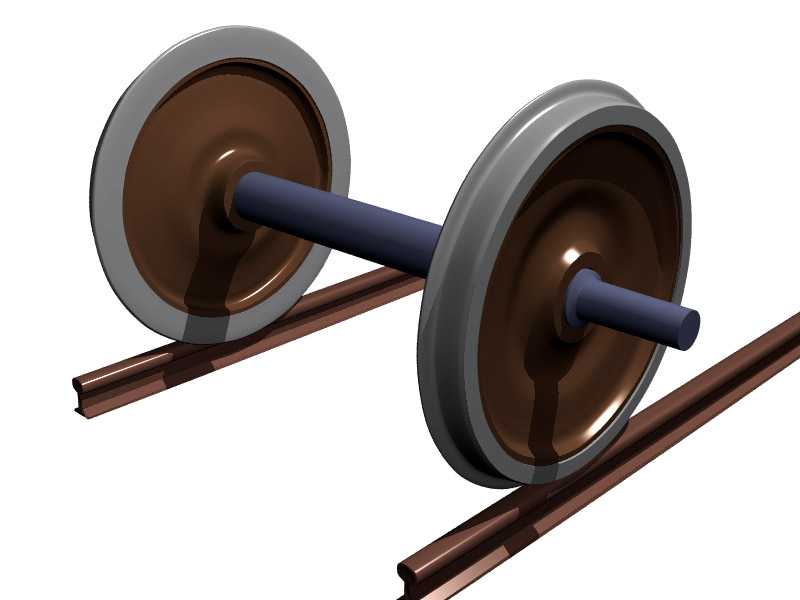
A straight axle is a single rigid shaft connecting a wheel on the left side of the vehicle to a wheel on the right side. The axis of rotation fixed by the axle is common to both wheels. Such a design can keep the wheel positions steady under heavy stress, and can therefore support heavy loads. Straight axles are used on trains (that is, locomotives and railway wagons), for the rear axles of commercial trucks, and on heavy-duty off-road vehicles. The axle can optionally be protected and further reinforced by enclosing the length of the axle in a housing.

In split-axle designs, the wheel on each side is attached to a separate shaft. Modern passenger cars have split-drive axles. In some designs, this allows independent suspension of the left and right wheels, and therefore a smoother ride. Even when the suspension is not independent, split axles permit the use of a differential, allowing the left and right drive wheels to be driven at different speeds as the automobile turns, improving traction and extending tire life.

A tandem axle is a group of two or more axles situated close together. Truck designs use such a configuration to provide a greater weight capacity than a single axle. Semi-trailers usually have a tandem axle at the rear.

Axles are typically made from SAE grade 41xx steel or SAE grade 10xx steel. SAE grade 41xx steel is commonly known as "chrome-molybdenum steel" (or "chrome-moly") while SAE grade 10xx steel is known as "carbon steel". The primary differences between the two are that chrome-moly steel is significantly more resistant to bending or breaking, and is very difficult to weld with tools normally found outside a professional welding shop.[2]

Drive axle

[edit]
Splines on a front drive axle

An axle that is driven by the engine or prime mover is called a drive axle.

Modern front-wheel drive cars typically combine the transmission (gearbox and differential) and front axle into a single unit called a transaxle. The drive axle is a split axle with a differential and universal joints between the two half axles. Each half axle connects to the wheel by use of a constant velocity (CV) joint which allows the wheel assembly to move freely vertically as well as to pivot when making turns.

In rear-wheel drive cars and trucks, the engine turns a driveshaft (also called a propeller shaft or tailshaft) which transmits the rotational force to a drive axle at the rear of the vehicle. The drive axle may be a live axle, but modern rear-wheel drive automobiles generally use a split axle with a differential. In this case, one half-axle or half-shaft connects the differential with the left rear wheel, a second half-shaft does the same with the right rear wheel; thus the two half-axles and the differential constitute the rear axle.[3] The front drive axle is providing the force to drive the truck. In fact, only one wheel of that axle is actually moving the truck and trailer down the road.

Some simple vehicle designs, such as leisure go-karts, may have a single driven wheel where the drive axle is a split axle with only one of the two shafts driven by the engine, or else have both wheels connected to one shaft without a differential (kart racing). However, other go-karts have two rear drive wheels too.

Lift axle

[edit]
A dump truck with an airlift pusher axle shown in the raised position

Some dump trucks and trailers may be configured with a lift axle (also known as an airlift axle or drop axle), which may be mechanically raised or lowered. The axle is lowered to increase the weight capacity, or to distribute the weight of the cargo over more wheels, for example, to cross a weight-restricted bridge. When not needed, the axle is lifted off the ground to save wear on the tires and axle, and to increase traction in the remaining wheels, and to decrease fuel consumption. Lifting an axle also alleviates lateral scrubbing of the additional axle in very tight turns, allowing the vehicle to turn more readily. In some situations, the removal of pressure from the additional axle is necessary for the vehicle to complete a turn at all.[4]

Several manufacturers offer computer-controlled airlifts so that the dead axles are automatically lowered when the main axle reaches its weight limit. The dead axles can still be lifted by the press of a button if needed, for better maneuverability.

Lift axles were in use in the early 1940s. Initially, the axle was lifted by a mechanical device. Soon hydraulics replaced the mechanical lift system. One of the early manufacturers was Zetterbergs, located in Östervåla, Sweden. Their brand was Zeta-lyften.

The liftable tandem drive axle was invented in 1957 by the Finnish truck manufacturer Vanajan Autotehdas, a company sharing history with Sisu Auto.

Full-floating vs semi-floating

[edit]

A full-floating axle carries the vehicle's weight on the axle casing, not the half-shafts; they serve only to transmit torque from the differential to the wheels. They "float" inside an assembly that carries the vehicle's weight. Thus the only stress it must endure is torque (not lateral bending force). Full-floating axle shafts are retained by a flange bolted to the hub, while the hub and bearings are retained on the spindle by a large nut.

In contrast, a semi-floating design carries the weight of the vehicle on the axle shaft itself; there is a single bearing at the end of the axle housing that carries the load from the axle and that the axle rotates through. To be "semi-floating" the axle shafts must be able to "float" in the housing, bearings and seals, and not subject to axial "thrust" and/or bearing preload. Needle bearings and separate lip seals are used in semi-floating axles with axle retained in the housing at their inner ends typically with circlips which are 3¾-round hardened washers that slide into grooves machined at the inner end of the shafts and retained in/by recesses in the differential carrier side gears which are themselves retained by the differential pinion gear (or "spider gear") shaft. A true semi-floating axle assembly places no side loads on the axle housing tubes or axle shafts.

Axles that are pressed into ball or tapered roller bearings, which are in turn retained in the axle housings with flanges, bolts, and nuts do not "float" and place axial loads on the bearings, housings, and only a short section of the shaft itself, that also carries all radial loads.

The full-floating design is typically used in most ¾- and 1-ton light trucks, medium-duty trucks, and heavy-duty trucks. The overall assembly can carry more weight than a semi-floating or non-floating axle assembly because the hubs have two bearings riding on a fixed spindle. A full-floating axle can be identified by a protruding hub to which the axle shaft flange is bolted.

The semi-floating axle setup is commonly used on half-ton and lighter 4×4 trucks in the rear. This setup allows the axle shaft to be the means of propulsion, and also support the weight of the vehicle. The main difference between the full- and semi-floating axle setups is the number of bearings. The semi-floating axle features only one bearing, while the full-floating assembly has bearings on both the inside and outside of the wheel hub. The other difference is axle removal. To remove the semi-floating axle, the wheel must be removed first; if such an axle breaks, the wheel is most likely to come off the vehicle. The semi-floating design is found under most ½-ton and lighter trucks, as well as in SUVs and rear-wheel-drive passenger cars, usually being smaller or less expensive models.

A benefit of a full-floating axle is that even if an axle shaft (used to transmit torque or power) breaks, the wheel will not come off, preventing serious accidents.

See also

[edit]

References

[edit]
[edit]
Revisions and contributorsEdit on WikipediaRead on Wikipedia
from Grokipedia
An axle is a central shaft or rod, typically cylindrical, that supports and facilitates the rotation of one or more wheels or gears, serving as a key component in transmitting torque and bearing loads in mechanical systems.[1] In its most basic form, the axle may rotate with the wheel (as in a live axle) or remain stationary while the wheel revolves around it (as in a dead axle), depending on the design requirements for power transmission and stability.[2] The wheel and axle together form one of the six classical simple machines, recognized for providing mechanical advantage by applying force to the larger wheel radius to produce greater torque at the smaller axle for tasks like lifting or turning.[3] The invention of the fixed wheel-and-axle system emerged around 3500 BCE in Mesopotamia, where early potters and cart builders crafted wooden disks with clay or wooden axles for potter's wheels and wheeled vehicles, marking a pivotal advancement in transportation and labor efficiency.[4] In modern applications, particularly automotive and heavy machinery, axles are engineered for durability under high stress, often made from forged steel or alloys to withstand bending, torsion, and shear forces while integrating with suspensions, differentials, and brakes.[5] Common types include the live axle, which drives the wheels and transmits power from the engine (prevalent in rear-wheel-drive trucks); the dead axle, a non-powered support beam for steering or trailing wheels; the stub axle, a short shaft for independent wheel suspension in front axles; and the transaxle, a compact unit combining transmission and axle for front-wheel-drive vehicles.[2] These variations optimize vehicle handling, load distribution, and efficiency, with innovations like independent suspension axles improving ride comfort since the early 20th century.[6]

Fundamentals

Definition and Function

An axle is defined as a central shaft or beam that connects a pair of wheels or other rotating elements in a mechanical system, facilitating their rotation while supporting applied loads.[5] In engineering applications, particularly vehicles, the axle serves as a structural component that bears the weight of the vehicle and its payload, distributing these loads across the connected wheels to ensure stability and efficient motion.[7] The primary functions of an axle include transmitting torque in driven configurations, supporting vertical loads, maintaining wheel alignment, and integrating with suspension systems for controlled vehicle dynamics. When power is applied, such as from an engine or motor, the axle conveys rotational force—or torque—to the wheels, enabling propulsion; this is essential in systems where the axle rotates with the wheels.[8] Load support involves withstanding static and dynamic forces, preventing deformation under weight that could compromise handling.[9] Wheel alignment is preserved through the axle's rigid structure, which keeps wheels parallel and perpendicular to the vehicle's frame, reducing tire wear and improving steering precision; this aligns with suspension components that absorb shocks while the axle provides a fixed reference for geometry.[10] Integration with suspension allows the axle to articulate with the vehicle's chassis, balancing rigidity for load bearing with flexibility for road irregularities. From a physics perspective, axles embody principles of rotational motion, where torque $ T $ drives the system via the relation $ \vec{T} = \vec{r} \times \vec{F} $, with magnitude $ T = r F \sin \theta $ (often $ T = r F $ for perpendicular force $ F $ at radius $ r $); this transmits power as $ P = T \omega $, where $ \omega $ is angular velocity.[11] Under load, axles experience shear stress from torsion, quantified as $ \tau = \frac{T c}{J} $, where $ c $ is the outer radius and $ J $ is the polar moment of inertia; this stress distributes across the cross-section, with maximum values at the surface, influencing material selection to avoid failure.[12] Axles may be fixed (non-rotating, with wheels spinning around them for load support only) or rotating (turning with the wheels to transmit torque), distinguishing their roles in passive versus powered applications.[9]

Historical Development

The origins of the axle trace back to approximately 3500 BC in Mesopotamia, where it was integrated into the earliest wheeled carts for transporting loads, revolutionizing human mobility and trade. These initial designs featured solid wooden wheels mounted on wooden axles, often with the axle and wheels rotating together as a single unit, which provided basic load-bearing support while minimizing friction compared to dragging sledges. Archaeological evidence from sites like Uruk supports this development, highlighting the axle's role in enabling efficient overland transport in ancient Sumerian society.[13] During the Bronze Age around 2000 BC, axle technology advanced with the transition to fixed axles—where the axle remained stationary relative to the vehicle frame while wheels rotated independently on bearings—facilitating smoother and more efficient motion in chariots and wagons. This innovation reduced drag and allowed for better maneuverability, particularly in military applications like two-wheeled war chariots used by civilizations such as the Hittites and Egyptians, which could achieve higher speeds and stability on varied terrain. The shift marked a key engineering milestone, as evidenced by chariot remains from archaeological digs in the Near East.[14] In the Renaissance period, the wheel-and-axle system gained formal recognition as one of the six classical simple machines, alongside the lever, pulley, inclined plane, wedge, and screw, with scholars like Leonardo da Vinci illustrating its applications in mechanical designs such as cranes and mills. Da Vinci's notebooks demonstrate how the system provided mechanical advantage through the ratio of the wheel's radius to the axle's radius (MA = r_wheel / r_axle), amplifying torque for practical inventions. This conceptualization built on ancient Greek ideas but was refined during the 15th and 16th centuries to underpin broader advancements in engineering and mechanics.[15] The 19th and 20th centuries brought material and functional innovations to axles, with steel construction introduced in late-1800s automobiles to withstand higher stresses from internal combustion engines. A notable 20th-century development was the 1957 invention of the liftable tandem drive axle by Finnish manufacturer Vanajan Autotehdas, allowing trucks to adjust axle load distribution for improved fuel efficiency and road compliance. In the 1930s, axles integrated with independent suspension systems in passenger cars, such as General Motors' "Knee Action" front suspension introduced in 1934, enhancing ride comfort by isolating each wheel's movement.[16] Modern milestones in the 21st century include the rise of electric axles (e-axles) in electric vehicles, which compactly integrate electric motors, gearboxes, and power electronics directly into the axle assembly for efficient propulsion and space savings, as adopted in production models from manufacturers like Tesla and Nissan since the 2010s. Recent advancements as of 2024 include highly integrated "12-in-1" e-axle systems, such as those introduced by BYD, combining multiple components like motors, inverters, and transmissions into a single unit to further improve efficiency and reduce complexity in electric vehicles.[17][18] This evolution supports the shift toward sustainable transportation by optimizing energy use and reducing drivetrain complexity.

Types of Axles

Dead Axles

A dead axle, also known as a lazy axle, is a non-rotating or fixed structural component that supports the vehicle's weight and maintains wheel position without transmitting power to the wheels, allowing the wheels to rotate independently on bearings mounted to the axle.[2][9] In this configuration, the axle itself remains stationary relative to the chassis, while the wheels spin freely via low-friction bearings, distinguishing it from driven axles that rotate with the wheels.[19] Dead axles are primarily used as front axles in rear-wheel-drive vehicles, where they bear the vehicle's load, facilitate steering, and provide structural support without the need for torque transfer from the drivetrain.[20] This setup is common in configurations where power is delivered only to the rear wheels, allowing the front dead axle to focus solely on stability and maneuverability.[21] Key configurations of dead axles include straight beam axles, which consist of a rigid, continuous shaft connecting the two wheels laterally and often serving as a stressed member in the suspension, and stub axles, which are shorter protrusions attached to steering knuckles to support individual wheels and enable pivoting for steering.[2][6] These designs frequently integrate with suspension systems like leaf springs, where the axle beam is mounted to the springs via U-bolts, providing vertical compliance while distributing loads across the vehicle.[22] Dead axles offer advantages such as structural simplicity, which reduces manufacturing complexity and maintenance needs; cost-effectiveness due to fewer components compared to powered systems; and high durability under compressive and bending loads, making them suitable for heavy-duty applications.[23] However, they provide poorer handling in rough terrain because the rigid connection between wheels limits independent movement, potentially leading to reduced traction and stability on uneven surfaces.[2] Examples of dead axles include the front axles in heavy-duty trucks, which support substantial loads during hauling, and those in older passenger cars with rear-wheel-drive layouts, such as classic sedans from the mid-20th century.[9] Load capacity for these axles is often assessed through bending moment calculations; for a uniform beam under central loading, the maximum bending moment is given by $ M = \frac{F L}{4} $, where $ F $ is the applied force at the center and $ L $ is the beam span, helping engineers determine material strength requirements to prevent failure.[24]

Live Axles

Live axles, also referred to as drive axles, are rotating components in vehicles that transmit torque from the engine or transmission to the drive wheels, enabling propulsion and vehicle motion. Unlike non-driven axles, live axles actively deliver power, making them essential in rear-wheel-drive (RWD), front-wheel-drive (FWD), and all-wheel-drive (AWD) or four-wheel-drive (4WD) systems.[25] Key components of live axles include axle shafts, which directly transfer torque to the wheels; a differential, which permits the wheels to rotate at varying speeds—such as during cornering—to prevent tire scrubbing; and universal joints, which connect the driveshaft to the differential and allow for angular misalignment and suspension articulation. These elements ensure efficient power delivery while accommodating the dynamic movements of the vehicle chassis relative to the wheels.[25][26] Live axles appear in various configurations depending on the drivetrain layout. In RWD vehicles, the rear live axle receives torque via a driveshaft from the transmission, providing balanced weight distribution for performance applications. Front live axles are common in 4WD systems, where a transfer case splits power to both axles for enhanced traction. Transaxles, which combine the transmission, differential, and axle into a single unit, are often employed in FWD setups to optimize packaging and reduce driveline length, though rear transaxles appear in some mid-engine or performance vehicles.[25] From an engineering perspective, live axles facilitate torque distribution through the differential, which balances power between wheels while the final drive gear ratio—calculated as the number of teeth on the ring gear divided by the teeth on the pinion gear—multiplies torque and reduces rotational speed at the wheels for optimal performance. For instance, a higher ratio like 4.10:1 (41 ring gear teeth to 10 pinion teeth) boosts low-end torque for acceleration, while a lower ratio like 2.15:1 favors highway efficiency by allowing lower engine RPM. This setup is particularly robust for off-road applications, offering superior durability and wheel articulation over rough terrain. However, the solid construction of live axles contributes to higher unsprung weight, which can compromise ride quality and handling by increasing suspension harshness and reducing responsiveness to road imperfections.[27][28][10]

Specialized Axles

Specialized axles represent adaptations of traditional designs to meet unique operational demands, such as variable loading, extreme terrain, or electrification, enhancing efficiency, durability, and performance in specific applications. Lift axles are retractable auxiliary axles primarily used in heavy-duty trucks to optimize weight distribution and comply with bridge laws. By hydraulically or pneumatically raising the axle when the vehicle is lightly loaded, they prevent excessive stress on infrastructure and allow operators to maximize payload capacity without exceeding legal limits. This design reduces tire wear by minimizing road contact during unloaded travel, potentially extending tire life and improving fuel efficiency by up to 5%.[29][30] Portal axles feature an elevated axle housing with integrated gearboxes at each wheel hub, providing significant ground clearance for off-road operations while maintaining a lower center of gravity compared to lifted suspensions. The portal gear reduction, often achieving ratios of 2:1 or higher, multiplies torque at the wheels, enabling better traction on uneven terrain without requiring larger, heavier tires. Originally prototyped in 1938 by Ferdinand Porsche for German military vehicles during World War II, such as the Volkswagen Kübelwagen, portal axles became staples in military applications for their ability to navigate rough landscapes while supporting heavy loads. Today, they remain common in military trucks like the Humvee and Unimog series.[31][32] Independent suspension axles, encompassing independent front suspension (IFS) and independent rear suspension (IRS), permit each wheel to move vertically without affecting the opposite wheel on the same axle, contrasting with rigid beam designs. In IFS systems, typically found on the front of modern vehicles, control arms or struts allow precise wheel articulation, enhancing steering response and ride comfort over bumps. IRS extends this to the rear, using multi-link or double-wishbone setups to maintain optimal tire contact during cornering or load shifts. These configurations improve overall handling by reducing body roll and unsprung weight, leading to better stability and traction, particularly on paved roads and in dynamic driving scenarios.[33][34] Tandem axles consist of two closely spaced axles that share load in commercial vehicles, increasing gross weight capacity while distributing forces to prevent overload on any single point. Pusher axles, positioned ahead of the drive axles, and tag axles, located behind them, serve as non-driven auxiliaries that can be lifted when not required, further aiding maneuverability and compliance with regulations. In the United States, federal standards under the Department of Transportation limit single axles to 20,000 pounds, tandem axles to 34,000 pounds, enabling safer and more efficient hauling in applications like dump and refuse trucks.[35][36][37] Electric axles, or e-axles, integrate an electric motor, inverter, and gearbox directly into the axle assembly, forming a compact propulsion unit for electric vehicles (EVs). This design eliminates the need for separate transmission tunnels, reducing vehicle weight and complexity while enabling all-wheel drive configurations with minimal packaging. Development accelerated in the early 2010s as EV adoption grew, with suppliers like ZF and Bosch introducing production-ready units that combine propulsion and steering functions. E-axles enhance efficiency by optimizing torque delivery and regenerative braking directly at the wheels.[17][38][39]

Design and Construction

Structural Components

The primary structural components of an axle assembly include the axle shaft, housing, bearings, and seals, each designed to ensure load transmission, protection, and smooth rotation. The axle shaft, typically solid for heavy-duty applications or hollow to reduce weight in lighter vehicles, serves as the core element connecting wheels and transmitting torque in live axles. In electric vehicle designs, axle shafts may integrate with electric motors in e-axle units for compact power delivery.[40] The housing encases the shaft and differential components, providing structural integrity and protection from contaminants, while bearings support rotational movement and seals prevent lubricant leakage and ingress of debris.[41][42] Materials for these components prioritize strength, durability, and weight efficiency. Axle shafts are commonly fabricated from high-strength steel alloys such as AISI 1045 carbon steel, which offers a balance of toughness and machinability, often enhanced through heat treatments like induction hardening to improve fatigue resistance under cyclic loading.[43] Housings are typically made from cast iron for its superior damping and wear resistance in heavy-duty setups or aluminum alloys for lightweighting in passenger vehicles, reducing overall vehicle mass by up to 20-30% compared to steel equivalents.[44][45] Bearings utilize hardened steel or ceramic elements in ball or roller configurations to minimize friction, with seals often employing elastomeric materials like nitrile rubber for effective sealing under dynamic conditions. In modern designs, composite materials such as glass-fiber-reinforced polymers are increasingly integrated into axle shafts for enhanced stiffness-to-weight ratios, particularly in electric vehicle applications seeking to optimize energy efficiency.[46] Manufacturing processes emphasize precision and structural integrity to meet performance demands. Axle shafts are primarily produced through forging, where heated steel billets are shaped under high pressure to align grain structure and enhance mechanical properties, followed by machining for exact tolerances on splines and bearing surfaces.[47] Housings undergo casting in molds for complex geometries, with subsequent welding of tubes or reinforcements using techniques like friction stir welding to join dissimilar metals without compromising strength, and final machining ensures precise fits for bearings and seals.[45] These processes allow for scalable production while maintaining component reliability under operational stresses. Load considerations in axle design focus on stress analysis to prevent failure, particularly torsional shear stress in the shaft, calculated as τ=TrJ\tau = \frac{T r}{J}, where τ\tau is the shear stress, TT is the applied torque, rr is the radial distance from the center, and JJ is the polar moment of inertia.[48] This formula guides material selection and sizing to ensure the shaft withstands peak torques without exceeding yield limits, typically targeting shear stresses below 100-150 MPa for steel alloys depending on application. Integration points include kingpins, which connect the axle to steering knuckles for pivotal movement in front axles, and spindles, which mount wheels and interface with bearings to facilitate rotation.[49]

Axle Configurations

Axle configurations refer to the arrangements of bearings and supports that determine how the wheel hub interacts with the axle shaft, influencing load distribution, maintenance, and durability in vehicles. These designs primarily apply to live axles in rear-drive systems, where the shaft transmits torque while bearings manage radial and axial loads from the vehicle's weight and motion.[50] In a semi-floating axle, the bearings support both the axle shaft and the wheel hub directly, with a single bearing typically mounted at the outer end of the shaft inside the axle housing. This setup allows the shaft to bear the vehicle's weight, tractive forces, and side loads in addition to torque transmission, making it a compact design with fewer components. Common in passenger cars and light-duty vehicles, semi-floating axles prioritize simplicity and cost-effectiveness but can experience higher stress on the shaft, potentially leading to bending under heavy loads.[50][51] The full-floating axle separates these responsibilities by mounting the wheel hub on two bearings—often tapered roller types—located on the axle housing, independent of the shaft. Here, the shaft only transmits torque from the differential to the wheel, while the housing and hub handle all weight, shear, and lateral forces; this enables shaft removal without dropping the wheel, enhancing serviceability. Ideal for heavy-duty applications like trucks and off-road vehicles, full-floating designs excel in high-shear scenarios, such as towing or rough terrain, by reducing shaft fatigue and improving overall reliability.[52][53] A three-quarter floating axle serves as a hybrid, featuring a single bearing positioned farther out on the axle tube to partially relieve the shaft of weight while still supporting some bending moments. The vehicle's weight transfers primarily to the housing, but the shaft bears side skid and torsional loads, offering a balance between the simplicity of semi-floating and the robustness of full-floating systems. This configuration is used in medium-duty trucks and some specialty vehicles, providing cost savings over full-floating setups without the full vulnerability to shaft stress seen in semi-floating designs.[51][50] Comparatively, full-floating axles handle greater shear loads—up to 20,000 pounds or more in heavy applications—making them suitable for off-road and commercial use, whereas semi-floating axles, typically rated for 4,000-6,500 pounds in light-duty applications, rely on fewer parts but risk shaft deflection or failure under overload. Three-quarter floating axles bridge this gap with moderate strength at lower complexity.[54] In terms of materials, these floating setups often incorporate high-strength steel shafts to complement the bearing arrangements.[52] The evolution from fixed to floating configurations began in the early 20th century, driven by the need for improved reliability in emerging truck fleets. By 1936, Chevrolet introduced the full-floating rear axle in heavy-duty trucks, shifting weight support away from the shaft to enhance durability and prevent breakdowns under load, marking a pivotal advancement for commercial transport.[55][53]

Applications

Vehicle Applications

In automotive applications, front-wheel-drive (FWD) vehicles commonly employ stub axles at the front wheels to facilitate steering while supporting the drive components. These stub axles, integrated with kingpin assemblies, serve as the primary load-bearing members for the front wheels, enabling precise directional control and torque transmission to the driven wheels.[56] In contrast, rear-wheel-drive (RWD) vehicles utilize live rear axles to deliver power from the engine to the rear wheels, enhancing traction during acceleration by rigidly connecting both wheels through a differential that distributes torque effectively.[57] Heavy-duty trucks rely on tandem live axles equipped with differentials to handle substantial hauling loads, distributing weight across multiple axles for stability and power delivery in vocational and on-highway operations. These configurations, such as hypoid gear tandems, support high-torque demands while maintaining durability under heavy payloads.[58] In the European Union, such axles must comply with regulations limiting driven axle loads to a maximum of 11.5 tonnes and tandem axle groups to 11.5–19 tonnes based on spacing, ensuring road infrastructure preservation.[59] Off-road vehicles and sport utility vehicles (SUVs) favor solid live axles for their superior durability over rough terrain, providing a rigid structure that withstands impacts and maintains wheel alignment under extreme stress. These axles are often paired with locking differentials to maximize traction by forcing equal wheel rotation, preventing power loss on uneven surfaces.[60] In railway vehicles, axles form the core of wheelsets, rigidly connecting paired wheels to transmit tractive effort, bear vertical loads up to 25 tonnes per axle in freight cars, and ensure stability at speeds exceeding 300 km/h in high-speed trains. Made from high-strength forged steel alloys compliant with standards like UIC 518 for dynamic load acceptance, railway axles incorporate press-fitted wheels and integrate with bogie suspensions to minimize derailment risks and optimize track wear.[61] Electric vehicles incorporate e-axles, which integrate electric motors, inverters, and gearboxes directly into the axle assembly, significantly reducing drivetrain complexity by eliminating separate transmission components and minimizing overall size and weight. This design, pioneered in production models since the 2010s, enhances efficiency and packaging; for instance, Tesla vehicles employ dual-axle motor setups to achieve all-wheel drive without traditional mechanical linkages.[38][62] Axle ratios, or final drive gear ratios, are selected to balance acceleration and fuel economy, with a common example being 3.73:1, which provides responsive low-end torque for quicker starts while allowing reasonable highway efficiency by keeping engine RPMs moderate at cruising speeds.[63]

Non-Vehicle Applications

In simple machines, the wheel and axle configuration provides mechanical advantage by amplifying force, calculated as the ratio of the wheel's diameter to the axle's diameter, allowing easier manipulation of loads. For instance, in a wheelbarrow, the large wheel diameter relative to the small axle enables a person to lift and transport heavy materials with reduced effort, as the mechanical advantage can exceed 10 in typical designs where the wheel radius is significantly larger than the axle.[3] Similarly, doorknobs operate on this principle, where turning the larger knob applies torque to the smaller axle connected to the latch, providing a mechanical advantage of around 5 to 10 depending on dimensions, facilitating door operation without excessive force.[64] Pulleys in lifting systems also incorporate axles as fixed pins supporting the rotating wheel, which redirects force and reduces friction in hoisting applications like construction scaffolds.[65] In industrial settings, axles support material handling in conveyor systems, where rollers mounted on fixed axles rotate to move belts carrying bulk goods such as ores or packages, minimizing friction and enabling continuous operation under high loads up to several tons per roller.[66] Wind turbines utilize a robust main axle, or low-speed shaft, to transmit rotational energy from the blades to the gearbox, designed to withstand variable wind loads and torques exceeding 1 million Nm while maintaining alignment through spherical roller bearings for longevity in offshore or onshore installations.[67][68] In aviation, landing gear axles support the aircraft's weight during ground operations and absorb landing impacts, with designs for commercial jets handling loads over 10 tonnes per main gear axle and forces up to 5-6g. Constructed from high-strength titanium or steel alloys, these axles integrate with shock struts and brakes to ensure durability under cyclic fatigue and corrosion in harsh environments.[69] For bicycles and hand carts, fixed rear axles provide structural stability by rigidly connecting wheels to the frame, often with quick-release mechanisms using 9-10 mm diameter hollow axles and 5 mm skewers for easy removal and secure locking during low-speed transport of goods.[70] In amusement rides, roller coaster axles connect polyurethane-tired wheels to vehicles via bearings, ensuring safety through upstop and side-friction configurations that prevent derailment under forces up to 5g, with spring-loaded designs adapting to track curves for smooth, high-speed operation.[71] Household appliances like washing machines employ gearbox axles to transfer motor power, with concentric inner and outer shafts driving the agitator and tub separately; the outer axle, typically 20-30 mm in diameter, handles centrifugal loads during spin cycles reaching 1000 rpm, reducing wear through precise gearing.[72] These non-vehicle uses highlight axles' advantages in low-speed, high-load scenarios, where they lower friction by up to 90% compared to sliding contacts, enhancing efficiency and durability in stationary or semi-static machinery.[73]

References

User Avatar
No comments yet.