Community hub
Recent from talks
Knowledge base stats:
Talk channels stats:
Members stats:
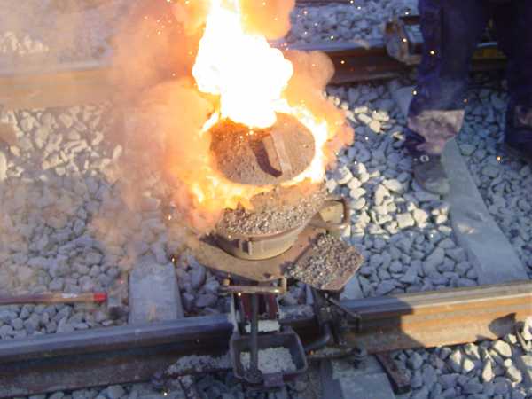
Exothermic welding
Exothermic welding, also known as exothermic bonding, thermite welding (TW), and thermite welding, is a welding process that employs molten metal to permanently join the conductors. The process employs an exothermic reaction of a thermite composition to heat the metal, and requires no external source of heat or current. The chemical reaction that produces the heat is an aluminothermic reaction between aluminium powder and a metal oxide.
In exothermic welding, aluminium dust reduces the oxide of another metal, most commonly iron oxide, because aluminium is highly reactive. Iron(III) oxide is commonly used:
The products are aluminium oxide, free elemental iron, and a large amount of heat. The reactants are commonly powdered and mixed with a binder to keep the material solid and prevent separation.
Commonly the reacting composition is five parts iron oxide red (rust) powder and three parts aluminium powder by weight, ignited at high temperatures. A strongly exothermic (heat-generating) reaction occurs that via reduction and oxidation produces a white hot mass of molten iron and a slag of refractory aluminium oxide. The molten iron is the actual welding material; the aluminium oxide is much less dense than the liquid iron and so floats to the top of the reaction, so the set-up for welding must take into account that the actual molten metal is at the bottom of the crucible and covered by floating slag.
Other metal oxides can be used, such as chromium oxide, to generate the given metal in its elemental form. Copper thermite, using copper oxide, is used for creating electric joints:
Thermite welding is widely used to weld railway rails. One of the first railroads to evaluate the use of thermite welding was the Delaware and Hudson Railroad in the United States in 1935 The weld quality of chemically pure thermite is low due to the low heat penetration into the joining metals and the very low carbon and alloy content in the nearly pure molten iron. To obtain sound railroad welds, the ends of the rails being thermite welded are preheated with a torch to an orange heat, to ensure the molten steel is not chilled during the pour.
Because the thermite reaction yields relatively pure iron, not the much stronger steel, some small pellets or rods of high-carbon alloying metal are included in the thermite mix; these alloying materials melt from the heat of the thermite reaction and mix into the weld metal. The alloying beads composition will vary, according to the rail alloy being welded.
The reaction reaches very high temperatures, depending on the metal oxide used. The reactants are usually supplied in the form of powders, with the reaction triggered using a spark from a flint lighter. The activation energy for this reaction is very high however, and initiation requires either the use of a "booster" material such as powdered magnesium metal or a very hot flame source. The aluminium oxide slag that it produces is discarded.
Hub AI
Exothermic welding AI simulator
(@Exothermic welding_simulator)
Exothermic welding
Exothermic welding, also known as exothermic bonding, thermite welding (TW), and thermite welding, is a welding process that employs molten metal to permanently join the conductors. The process employs an exothermic reaction of a thermite composition to heat the metal, and requires no external source of heat or current. The chemical reaction that produces the heat is an aluminothermic reaction between aluminium powder and a metal oxide.
In exothermic welding, aluminium dust reduces the oxide of another metal, most commonly iron oxide, because aluminium is highly reactive. Iron(III) oxide is commonly used:
The products are aluminium oxide, free elemental iron, and a large amount of heat. The reactants are commonly powdered and mixed with a binder to keep the material solid and prevent separation.
Commonly the reacting composition is five parts iron oxide red (rust) powder and three parts aluminium powder by weight, ignited at high temperatures. A strongly exothermic (heat-generating) reaction occurs that via reduction and oxidation produces a white hot mass of molten iron and a slag of refractory aluminium oxide. The molten iron is the actual welding material; the aluminium oxide is much less dense than the liquid iron and so floats to the top of the reaction, so the set-up for welding must take into account that the actual molten metal is at the bottom of the crucible and covered by floating slag.
Other metal oxides can be used, such as chromium oxide, to generate the given metal in its elemental form. Copper thermite, using copper oxide, is used for creating electric joints:
Thermite welding is widely used to weld railway rails. One of the first railroads to evaluate the use of thermite welding was the Delaware and Hudson Railroad in the United States in 1935 The weld quality of chemically pure thermite is low due to the low heat penetration into the joining metals and the very low carbon and alloy content in the nearly pure molten iron. To obtain sound railroad welds, the ends of the rails being thermite welded are preheated with a torch to an orange heat, to ensure the molten steel is not chilled during the pour.
Because the thermite reaction yields relatively pure iron, not the much stronger steel, some small pellets or rods of high-carbon alloying metal are included in the thermite mix; these alloying materials melt from the heat of the thermite reaction and mix into the weld metal. The alloying beads composition will vary, according to the rail alloy being welded.
The reaction reaches very high temperatures, depending on the metal oxide used. The reactants are usually supplied in the form of powders, with the reaction triggered using a spark from a flint lighter. The activation energy for this reaction is very high however, and initiation requires either the use of a "booster" material such as powdered magnesium metal or a very hot flame source. The aluminium oxide slag that it produces is discarded.