Hubbry Logo
Leaf springLeaf springMain
Open search
Leaf spring
Community hub
Leaf spring
logo
8 pages, 0 posts
0 subscribers
Be the first to start a discussion here.
Leaf spring
Leaf spring
from Wikipedia

A traditional semi-elliptical Hotchkiss leaf spring arrangement. On the left, the spring is connected to the frame through a shackle.

A leaf spring is a simple form of spring commonly used for suspension in wheeled vehicles. Originally called a laminated or carriage spring, and sometimes referred to as a semi-elliptical spring, elliptical spring, or cart spring, it is one of the oldest forms of vehicle suspension. A leaf spring is one or more narrow, arc-shaped, thin plates that are attached to the axle and chassis in a way that allows the leaf spring to flex vertically in response to irregularities in the road surface. Lateral leaf springs are the most commonly used arrangement, running the length of the vehicle and mounted perpendicular to the wheel axle, but numerous examples of transverse leaf springs exist as well.

Leaf springs can serve multiple suspension functions: location, springing, and to some extent damping as well, through interleaf friction. However, this friction is not well controlled, resulting in stiction and irregular suspension motions. For this reason, some manufacturers have used mono-leaf springs.

Operation and basic design

[edit]
Generic diagram of a leaf spring pack, without eyes; leaves are fastened together by the centre bolt, midway along the length of the spring, and lateral alignment is enforced by multiple clips

A leaf spring takes the form of a slender arc-shaped length of spring steel of a rectangular cross-section. In the most common configuration, the centre of the arc provides the location for the axle, while loops formed at either end provide for attaching to the vehicle chassis. For very heavy vehicles, a leaf spring can be made from several leaves stacked on top of each other in several layers, often with progressively shorter leaves. The longest leaf is also known as the main, master, or No. 1 leaf, with leaves numbered in descending order of length.[1]: 1–3  The eyes at the end of the leaf spring are formed into the master leaf.[2]: 6  In general, aside from the main leaf, the other leaves are tapered at each end.[2]: 8  Sometimes auxiliary or rebound leaves are part of the main spring pack, in which case the auxiliary leaf closest to the main leaf is No. 1, the next closest is No. 2, etc.[1]: 3  The leaves are attached to each other through the centre bolt, which is at or near the mid-point along the length of the leaf spring.[2]: 8  To ensure that leaves remain aligned laterally, several methods can be used, including notches and grooves between leaves or external clips.[2]: 9–12 

Spring steels were discovered to be most efficient at approximately 1% carbon content.[2]: 13–15  Individual leaf thickness is specified by the Stubbs or Birmingham gauge, with typical thicknesses ranging between 0.203 to 0.375 in (5.2 to 9.5 mm) (6 to 3/8 or 00 gauge).[2]: 16  The material and dimensions should be selected such that each leaf is capable of being hardened to have a fully martensitic structure throughout the entire section. Suitable spring steel alloys include 55Si7, 60Si7, 65Si7, 50Cr4V2, and 60Cr4V2.[1]: 6 

Characteristics

[edit]
Each side of this rear axle is suspended by a leaf spring. The front eye of each leaf spring is secured to the frame; the rear eye is attached by a shackle that pivots to allow the spring to lengthen as it flexes.

The two ends of a leaf spring usually are formed into round eyes or eyelets, through which a fastener connects each end of the spring to the vehicle frame or body. Some springs terminated in a concave end, called a spoon end (seldom used now), to carry a swivelling member instead. One eye is usually fixed but allowed to pivot with the motion of the spring, whereas the other eye is fastened to a hinge mechanism that allows that end to pivot and undergo limited movement. A leaf spring can either be attached directly to the frame at both eyes or attached directly at one end, usually the front, with the other end attached through a shackle: a short swinging arm. The shackle takes up the tendency of the leaf spring to elongate when compressed and thus makes the suspension softer. The shackle provides some degree of flexibility to the leaf spring so that it does not fail when subjected to heavy loads. The axle is usually fastened to the middle of the spring by U-bolts.[3]

The leaf spring acts as a linkage to hold the axle in position and thus separate linkages are not necessary. The result is a suspension that is simple and strong. Inter-leaf friction dampens the spring's motion and reduces rebound, which, until shock absorbers were widely adopted, was a very significant advantage over helical springs.[4] However, because the leaf spring is also serving to hold the axle in position, soft springs—i.e. springs with low spring constant—are not suitable. The consequent stiffness, in addition to inter-leaf friction, makes this type of suspension not particularly comfortable for the riders.[citation needed]

Types

[edit]
Three-quarter-elliptic leaf spring on a carriage.

There are a variety of leaf springs, usually employing the word "elliptical". "Elliptical" or "full elliptical" leaf springs, patented in 1804 by the British inventor Obadiah Elliott, referred to two circular arcs linked at their tips. This was joined to the frame at the top centre of the upper arc, the bottom centre was joined to the "live" suspension components, such as a solid front axle. Additional suspension components, such as trailing arms, would usually be needed for this design, but not for "semi-elliptical" leaf springs as used in the Hotchkiss drive. That employed the lower arc, hence its name.

"Quarter-elliptic" springs often had the thickest part of the stack of leaves stuck into the rear end of the side pieces of a short ladder frame, with the free end attached to the differential, as in the Austin Seven of the 1920s. As an example of non-elliptic leaf springs, the Ford Model T had multiple leaf springs over its differential that were curved in the shape of a yoke. As a substitute for dampers (shock absorbers), some manufacturers laid non-metallic sheets in between the metal leaves, such as wood.

Elliot's invention revolutionized carriage design and construction, removing the need for a heavy perch and making transportation over rough roadways faster, easier, and less expensive.[5]

Tapered or parabolic leaf spring diagram

A more modern implementation is the parabolic leaf spring. This design is characterized by fewer leaves whose thickness varies from centre to ends following a parabolic curve. The intention of this design is to reduce inter-leaf friction, and therefore there is only contact between the leaves at the ends and at the centre, where the axle is connected. Spacers prevent contact at other points. Aside from weight-saving, the main advantage of parabolic springs is their greater flexibility, which translates into improved ride quality, which approaches that of coil springs; the trade-off is reduced load carrying capability. They are widely used on buses for improved comfort.

A further development by the British GKN company and by Chevrolet, with the Corvette, among others, is the move to composite plastic leaf springs. Nevertheless, due to the lack of inter-leaf friction and other internal dampening effects, this type of spring requires more powerful dampers/shock absorbers.

Typically when used in automobile suspension the leaf both supports an axle and locates/partially locates the axle. This can lead to handling issues (such as "axle tramp"), as the flexible nature of the spring makes precise control of the unsprung mass of the axle difficult. Some suspension designs use a Watts link (or a Panhard rod) and radius arms to locate the axle and do not have this drawback. Such designs can use softer springs, resulting in a better ride. Examples include the various rear suspensions of Austin-Healey 3000s and Fiat 128s.

History

[edit]
17th-century coach spring in Lisbon Carriage Museum

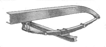
The earliest known leaf springs began appearing on carriages in France in the mid-17th century in the form of the two-part elbow spring (as the illustrated example from Lisbon), and later migrated to England and Germany,[6] appearing on the carriages of the wealthy in those countries around 1750.[2]: 1  Dr. Richard Lovell Edgeworth was awarded three gold medals by the Society of English Arts and Manufacturers in 1768 for demonstrating the superiority of sprung carriages. By 1796, William Felton's A Treatise on Carriages showed that leaf springs were being marketed regularly by the late 18th century carriage industry.[7]: 87–97 [2]: 1 

Obadiah Elliot is credited with inventing the modern leaf spring with his 1804 patent on elliptical leaf springs, which brought him significant recognition and revenue, and engineers began studying leaf springs to develop improved designs and manufacturing processes. The mechanics and deflection of leaf springs were developed by Clark (1855), Franz Reuleaux (1861),[8] and G.R. Henderson (1894).[2]: 1 [9][10] Improved steel rolling processes, process instruments, and spring steel alloys were developed during the latter half of the 19th century as well, making the manufacture of leaf springs more consistent and less expensive.[2]: 2 

Leaf spring on a German locomotive built by Orenstein-Koppel and Lübecker Maschinenbau

Leaf springs were very common on automobiles until the 1970s when automobile manufacturers shifted primarily to front-wheel drive, and more sophisticated suspension designs were developed using coil springs instead. Today leaf springs are still used in heavy commercial vehicles such as vans and trucks, SUVs, and railway carriages. For heavy vehicles, they have the advantage of spreading the load more widely over the vehicle's chassis, whereas coil springs transfer it to a single point. Unlike coil springs, leaf springs also locate the rear axle, eliminating the need for trailing arms and a Panhard rod, thereby saving cost and weight in a simple live axle rear suspension. A further advantage of a leaf spring over a helical spring is that the end of the leaf spring may be guided along a definite path. In many late 1990s and early 2000s trucks, the leaf spring is connected to a Hinkle Beam ball joint.

The leaf spring also has seen modern applications in cars. For example, the 1963 Chevrolet Corvette Sting Ray uses a transverse leaf spring for its independent rear suspension. Similarly, 2016 Volvo XC90 has a transverse leaf spring using composite materials for its rear suspension, similar in concept to the front suspension of the 1983 Corvette. This arrangement uses a straight leaf spring that is tightly secured to the chassis at the centre; the ends of the spring are bolted to the wheel suspension, allowing the spring to work independently on each wheel. This suspension is smaller, flatter and lighter than a traditional setup.

Manufacturing process

[edit]

Multi-leaf springs are made as follows.

  1. Pre-heat treatment process:
    1. thearing
    2. taper rolling
    3. trimming
    4. end cutting and pressing
    5. second warping
    6. scarfing and eye rolling
    7. nipping
    8. C’SKG punching
    9. centre hole drilling.
  2. Heat treatment processes:
    1. heating for hardening
    2. cambering
    3. quenching
    4. tempering.
  3. Post-heat treatment processes:
    1. rectification
    2. side bend removing
    3. bushing
    4. reaming
    5. clamp riveting.
  4. Assembly and surface finishes:
    1. shot peening
    2. painting
    3. assembling
    4. scragging
    5. marking and packing.

Heat treatment

[edit]
  1. Heating for hardening: Any metal, or alloy which can be hard drawn, or rolled to fairly high strength and retains sufficient ductility to form, may be used for springs, or any alloy which can be heat treated to high strength and good ductility before, or after forming may be used. For special spring properties such as good fatigue life, non-magnetic characteristics, resistance to corrosion, elevated temperatures and drift require special considerations. leaves are heated to critical temperature in an oil-fired hardening furnace. Usually temperature maintained is between 850°C and 950°C.
  2. Cambering: The top leaf is known as the master leaf. The eye is provided for attaching the spring with another machine member. The amount of bend that is given to the spring from the central line, passing through the eyes, is known as camber. The camber is provided so that even at the maximum load the deflected spring should not touch the machine member to which it is attached. The camber shown in the figure is known as positive camber. The central clamp is required to hold the leaves of the spring. Machine used for this operation is hydraulic press. Leaves are bent to required radius using a press. All the leaves are tested for required radius using cambering gauges.
  3. Quenching : Hot bent leaves kept in tray and quenched in oil bath to get martensite structure. Martensite is the hardest form of steel crystalline structure. Martensite is formed in carbon steels by rapid cooling that is quenching of austenite form of iron. The machine used is a conveyorised quench oil bath. The fire point of quenching oil is about 200°C and it is seen to that the oil temperature does not exceed 80°C. After quenching, the structure of the leaf spring becomes very hard and this property is not required. But this process is required to set the leaves to the correct radius after cambering. To remove hardness, tempering is done.
  4. Tempering: Tempering is a process of heat treating, which is used to increase the toughness. Quenched leaves are reheated to drop hardness to the required level. An electrically heated temperature furnace is used for this process. Hardness of the leaves is determined using Brinell hardness testing, a process that also relieves stresses. The temperature inside the machine is maintained between 540 and 680°C. The tempering process involves heating of leaves below their re-crystallization temperature then cooling them using water or air.

Other uses

[edit]

By blacksmiths

[edit]

Because leaf springs are made of relatively high quality steel, they are a favourite material for blacksmiths. In countries such as India, Nepal, Bangladesh, Philippines, Myanmar and Pakistan, where traditional blacksmiths still produce a large amount of the country's tools, leaf springs from scrapped cars are frequently used to make knives, kukris, and other tools.[11] They are also commonly used by amateur and hobbyist blacksmiths.

In trampolines

[edit]

Leaf springs have also replaced traditional coil springs in some trampolines (known as soft-edge trampolines), which improves safety for users and reduces risk of concussion.[12] The leaf springs are spaced around the frame as "legs" that branch from the base frame to suspend the jumping mat, providing flexibility and resilience.[13]

Clutches

[edit]

The "diaphragm" common in automotive clutches is a type of leaf spring.

Modernization

[edit]

Tuning (from English to tune, to adjust, to harmonise, to fine-tune) in the field of vehicles is a term that denotes the modification of a vehicle relative to mass production standards in order to adapt it to personal tastes or specific needs.[14][15] Suspension tuning includes changing springs, shock absorbers, sway bars, and other related components.[16] Many trucks are supported by leaf spring suspension.[17] Leaf spring suspensions provide exceptional articulation, higher load capacity, and can withstand significant abuse. With the right methods, they can be modified to help the vehicle carry heavier loads, have better articulation, or fit larger oversized tires. Some vehicles may be equipped with front and rear leaf springs or only rear leaf springs with independent front suspension. There are two main ways to upgrade leaf springs. The first is budget-friendly but very effective — adding a leaf to the factory leaf spring pack. This provides increased ground clearance and load capacity.[18] The second option is to replace the factory leaf spring packs. Overall, this approach changes every aspect of the rear suspension dynamics, giving you more control over outcomes including height, load capacity, wheel travel, etc.[19]

Some lifting methods are good for the rear but not for the front, such as lift blocks. Lifting the rear using blocks is a common way to achieve the desired height. This is done by installing a block of the desired lift height between the leaf spring and the leaf spring perch and fitting longer U-bolts. This is a poor method for the front, primarily due to safety issues during braking. When braking, the front wheels generate most of the braking force. The block moves this lateral force caused by braking higher above the axle than in its standard form. This can cause the block to shift out of place and a complete loss of control.

A more acceptable way to build up leaf springs is using add-a-leafs. This is done by inserting an additional leaf into the vehicle’s leaf spring pack. Using add-a-leafs will increase height but sometimes leads to a stiff suspension travel due to the added spring stiffness.

For off-road vehicles, the emphasis is on extending suspension travel and fitting larger tires. Larger tires — with bigger wheels or without — increase ground clearance, provide a smoother ride over rough terrain, offer additional cushioning, and reduce ground pressure (which is important on soft surfaces).[20][21] Often, the rear suspension of off-road vehicles is represented by leaf springs.

See also

[edit]

References

[edit]
[edit]
Revisions and contributorsEdit on WikipediaRead on Wikipedia
from Grokipedia
A leaf spring is a robust suspension element composed of multiple layers of flat, curved strips—known as leaves—stacked and clamped together to form a semi-elliptical or parabolic arch, designed to absorb shocks, distribute loads evenly, and provide stability in heavy-duty applications. These assemblies function by allowing the leaves to flex independently under load, with the longer master leaf bearing the primary stress while shorter leaves contribute progressively less, thereby vibrations and maintaining alignment during vehicle travel. Primarily utilized in rigid suspensions, leaf springs are installed longitudinally for commercial vehicles or transversely for balanced support on both sides. The origins of leaf springs trace back to the , where layered bronze components cushioned horse-drawn chariots over rough terrain, evolving into steel-based designs by the to enhance durability and ride comfort in carriages during the . A pivotal advancement occurred in 1804 when British inventor Elliott patented the elliptic leaf spring, revolutionizing vehicle suspension by stacking plates and pinning them for improved shock absorption and load handling in coaches. By the early , multi-leaf configurations became standard in automobiles, trucks, and railroads, supporting heavier loads and enabling through refined processing. Traditionally fabricated from high-carbon alloys such as 5160 (for and resistance), 9260 (for flexibility and shock absorption), or 1095 (for in high-performance scenarios), leaf springs undergo hot or cold forming processes to achieve their precise curvature and strength. In modern applications, composite materials like or carbon fiber reinforced with are increasingly adopted, offering up to 50% weight reduction, superior fatigue resistance, and better vibration damping compared to , as seen in commercial vehicles by manufacturers such as Ford, , and Daimler, including in electric and hybrid models for enhanced efficiency. Key uses span automotive suspensions in trucks, SUVs, and trailers for handling rough roads and heavy payloads; railroad cars to minimize freight impacts; and off-road vehicles for enhanced terrain adaptability. Despite competition from coil and air suspensions, leaf springs remain favored for their simplicity, cost-effectiveness, and reliability in commercial and heavy-duty sectors, with the composite market valued at approximately USD 85 million in 2023 and projected to reach USD 150 million by 2030.

Design and Operation

Basic Design

A leaf spring is a suspension component composed of a stack of flat, curved metal plates, known as leaves, of varying lengths that are clamped together at the center to form a semi-elliptical or similar arched shape. This laminated construction allows the assembly to support and distribute loads while maintaining structural integrity in vehicle applications. The leaves are typically arranged with the longest at the top and progressively shorter ones below, creating a layered beam that enhances flexibility and strength. Key components include the master leaf, which is the longest and uppermost plate, curved to provide the primary structural shape and often featuring eyes at its ends for attachment to the . Supporting this are the wrapped or graduated leaves, shorter plates that nest beneath the master leaf to share the load and prevent excessive bending in any single layer. Rebound clips secure the leaves together along their lengths to minimize separation during use, while a central bolt clamps the entire stack at the midpoint, aligning the components and serving as the primary attachment point for the . U-bolts encircle the center of the assembly to fasten it securely to the housing. In rigid axle suspension systems, the leaf spring functions dually as a load-bearing element and a structural locator, constraining the 's position relative to the while accommodating vertical movements. This evolved from early springs but remains fundamental in modern heavy-duty vehicles for its simplicity and durability. A typical side view diagram of a leaf spring illustrates the semi-elliptical arc formed by the stacked leaves, with the master leaf spanning the full length and shorter leaves tapering toward the ends, connected by the center bolt and secured by U-bolts at the midpoint. In cross-section, the assembly appears as a bundled stack of parallel plates, bound by rebound clips at intervals and the central bolt piercing through all layers for cohesion.

Principles of Operation

Leaf springs operate through the elastic deformation of their layered structure, where individual leaves slide and flex relative to one another under applied load. This mechanism allows the load to be distributed progressively from the outer, longer leaves to the inner, shorter leaves, preventing overload on any single component and enabling the spring to handle varying forces without failure. The primary function in energy management involves converting from road impacts or vehicle motion into stored through the bending of the leaves. As the spring deforms elastically, it absorbs shocks and vibrations; upon release of the load, the stored energy is gradually returned, contributing to a smoother ride by oscillations. For analytical purposes, the deflection of a leaf spring can be approximated using a simplified beam model derived from Euler-Bernoulli beam theory, which assumes small deflections and linear elastic behavior. The key for vertical deflection δ\delta under a central load PP for a simply supported beam configuration is: δ=3PL38EI\delta = \frac{3 P L^3}{8 E I} Here, LL is the effective span length, EE is the modulus of elasticity of the material, and II is the second moment of area (moment of inertia) of the cross-section. This formula arises from integrating the curvature equation d2ydx2=M(x)EI\frac{d^2 y}{dx^2} = \frac{M(x)}{E I} along the beam length, where M(x)M(x) is the bending moment, yielding the cubic dependence on length that highlights the spring's sensitivity to geometry. In vehicle suspension systems, leaf springs serve to locate the both laterally and vertically relative to the , while permitting articulation to accommodate uneven . By attaching directly to the and frame, they guide the axle's path during compression and rebound, maintaining alignment without additional linkages.

Mechanical Characteristics

Leaf springs demonstrate a progressive spring rate in multi-leaf configurations, where the effective increases nonlinearly with applied load as successive leaves come into contact and share the deflection. This behavior allows for a compliant initial response under light loads, transitioning to greater rigidity for heavy payloads, thereby optimizing ride quality and load handling. For and applications, representative spring rates typically range from 500 to 2000 lb/in, with specific examples including approximately 1100 lb/in for front suspensions and 1500 lb/in for rear suspensions in light-duty electric vehicles. The stress distribution within a leaf spring is governed by bending mechanics, with the maximum tensile and compressive stresses occurring at the upper and lower surfaces of each leaf. For a single leaf under load, the maximum bending stress σ\sigma is calculated as σ=3PL2bh2,\sigma = \frac{3PL}{2bh^2}, where PP is the load per leaf, LL is the effective span length, bb is the leaf width, and hh is the leaf thickness; this formula derives from the standard flexural stress equation for a simply supported beam under central loading, adapted to the semi-elliptic geometry of leaf springs. In multi-leaf assemblies, the total load is distributed across the leaves, reducing the stress per leaf proportionally to the number of active leaves, though initial loading concentrates on the longer master leaf. Leaf springs offer high cycle resistance attributable to the multi-leaf design, which distributes cyclic stresses and prevents localized overload on any single component, enabling endurance under millions of load cycles in vehicular service. Common failure modes include sagging from progressive deformation under sustained overload and cracking initiated at high-stress regions such as holes or edges due to propagation. Despite these, the design's robustness supports high load capacities at relatively low manufacturing costs compared to alternative suspension elements. However, inter-leaf introduces disadvantages, including accelerated through —exacerbated by moisture—and audible noise from rubbing during deflection, which can degrade long-term durability and ride comfort.

Types and Configurations

Conventional Multi-Leaf Types

Conventional multi-leaf leaf springs represent the traditional geometric configurations developed primarily in the 18th and 19th centuries for suspensions, consisting of multiple curved leaves stacked and clamped together to distribute loads and absorb shocks. These designs rely on the progressive stacking of leaves of graduated lengths, with the longest forming the master leaf at the base, to achieve balanced deflection and stress distribution across the pack. The full elliptic configuration, patented in by Obadiah Elliott, features paired upper and lower semi-elliptic packs connected at both ends to form a complete shape, with the upper arc attached to the and the lower to the . This design was commonly used in early horse-drawn carriages to provide even load sharing between the front and rear, enhancing ride comfort over uneven roads by allowing symmetric deflection. In rigid axle applications, full elliptics were mounted longitudinally to maintain stability during travel. The semi-elliptic type, the most prevalent conventional multi-leaf design, forms a curved arc resembling half an , with eyes at both ends for attachment—one fixed to the frame and the other to a for length accommodation during flexing. These springs typically comprise 5 to 15 layers of leaves, enabling them to support substantial loads while providing progressive stiffness. Widely adopted for rear axles in carriages and early vehicles, semi-elliptics were longitudinally mounted on rigid axles to ensure and effective shock absorption. Quarter-elliptic and three-quarter-elliptic configurations are shorter arc variants of the form, with the quarter-elliptic using a cantilevered quarter-circle shape fixed at one end and the three-quarter-elliptic extending to about three-quarters of an , also with one fixed end. These were employed in front axles of lighter carriages or in tandem setups for partial load support, offering simpler installation and flexibility in constrained spaces. Like other conventional types, they were oriented longitudinally on rigid axles to promote overall vehicle stability.

Mono-Leaf and Parabolic Variants

The mono-leaf spring represents a simplified variant of traditional leaf spring designs, consisting of a single leaf with either constant thickness or a tapered profile that varies in thickness along its length to optimize load distribution. Typically fabricated from high-carbon such as SAE 5160, the mono-leaf features a thicker central section—often 12-20 mm—and thinner ends around 8 mm, with a constant width of approximately 50 mm, eliminating the need for multiple leaves, clamps, or bolts. This design requires precise to ensure even stress distribution under load, as the single leaf must handle all deflection and support without interlayer support. Compared to conventional multi-leaf springs, the mono-leaf offers significant weight reduction and cost savings by minimizing material use and assembly components, making it suitable for vehicles where simplicity and ease of installation are prioritized. For instance, under a 2500 N load, optimized mono-leaf designs achieve deflections of 7-13 mm with maximum stresses of 162-269 N/mm², comparable to or better than multi-leaf equivalents at 255 N/mm² and 9.6 mm deflection, while reducing overall weight through fewer parts. However, the design demands higher-quality and accurate tapering to prevent localized stress concentrations, limiting its application to lower-load scenarios. Parabolic leaf springs advance the mono-leaf concept by incorporating a gradually decreasing thickness profile along the spring's length, forming a parabolic taper that ensures uniform stress distribution across the entire leaf under load. Constructed from alloy steels like SAE 5160 (0.6% C-Cr) or SAE 4161 (0.6% C-CrMo), these springs typically use 1-3 leaves rather than the 10+ in multi-leaf packs, with the primary leaf tapered from a thicker center to thinner ends via hot rolling, followed by hardening to ~450 HB and stress peening for fatigue resistance. This configuration minimizes material waste by concentrating strength where needed, achieving uniform stress levels that enhance durability without excess weight. A key advantage of parabolic variants is their 30-40% weight reduction compared to uniform-thickness multi-leaf springs, as demonstrated in applications like suspensions (from 7.8 kg to 4.4 kg) and axles (up to 44% savings, e.g., 162 kg to 90 kg for rear s), which improves and capacity while reducing . The reduced leaf count also lowers interleaf , resulting in a smoother ride with better articulation over uneven terrain and decreased dynamic for enhanced comfort in light trucks and recreational vehicles. Although requiring advanced for precise tapering, these springs maintain high load-bearing rates equivalent to multi-leaf designs, with the of potentially higher initial costs due to specialized alloys.

Transverse and Specialized Configurations

Transverse leaf springs are mounted perpendicular to the vehicle's longitudinal axis, spanning across the to support and locate the laterally while providing vertical compliance. This configuration integrates the spring's function with axle guidance, eliminating the need for separate locating links such as trailing arms or rods, which reduces complexity and cost in suspension design. In automotive applications, transverse leaf springs were notably employed in the from the C4 to C7 generations (1984–2019), where composite materials like were used for both front and rear s to achieve lightweight construction—typically under half the weight of equivalent coil springs—while also serving as an integral to control body roll. The spring is clamped at multiple points to the , allowing it to flex under load and maintain without additional sway bars in some setups. Similarly, modern hybrid vehicles like the utilize a rear transverse composite leaf spring made from fiber-reinforced , which replaces traditional coil springs to save space, reduce unsprung mass by up to 50%, and improve (NVH) characteristics by distributing loads more evenly across the . Platform leaf springs represent a specialized variant for multi-axle vehicles such as trailers and heavy-duty trucks, featuring a flat or extended assembly where a pair of semi-elliptical springs—one oriented downward and the other upward—cradle the between them to provide balanced support over longer spans. This design enhances load distribution across multiple axles, promoting stability in extended configurations like or tri-axle setups. Continuous leaf springs extend this concept further, forming an uninterrupted beam-like structure that spans across two or more axles in trailers, allowing for smoother articulation and reduced inter-axle transfer during turns or uneven . Tandem leaf spring configurations are prevalent in heavy-duty trucks, where dual axles are linked by shackle assemblies that permit extension under load to maintain consistent and prevent excessive camber changes. These setups, often with 10-12 leaves per spring, support capacities exceeding 50,000 lbs per while integrating with walking beam linkages for off-highway durability. Tension leaf springs represent a recent specialized configuration, particularly for heavy-duty trucks as of 2023, utilizing composite materials in a U-bolt-less design that provides progressive spring rates for improved ride quality and further weight reduction on rear . While transverse and specialized configurations offer compactness and inherent axle location—reducing parts count and —they are susceptible to camber variations under asymmetric loading, potentially affecting wear and handling stability compared to independent suspensions.

Historical Development

Ancient and Early Origins

The earliest precursors to leaf springs emerged in the , around 2000 BCE, where primitive laminated wooden bows served as rudimentary shock absorbers in horse-drawn across ancient civilizations. In during the New Kingdom (c. 1550–1070 BCE), artifacts from Tutankhamun's tomb reveal chariots equipped with a suspension system featuring flexible joints allowing sliding for damping and a woven leather floor to absorb vibrations, providing improved stability over rough desert terrain. These designs, evidenced by preserved chariot components, allowed for greater speed and stability in warfare and transport. Early spoked-wheel chariots from around 2000 BCE in the , including Mesopotamian regions like the and , improved mobility but lacked advanced suspension, relying on wheel design for basic shock absorption. By the medieval period in (14th–15th centuries), wagon suspensions primarily used straps or s for basic shock absorption, providing modest improvements over rigid axles on unpaved roads, though their implementation remained sporadic and limited to wealthier merchants or use. from period illustrations and surviving frames suggests these provided a foundational evolution from rigid axles, prioritizing durability over comfort in an era of poor . Roman vehicles used for basic damping; by the 15th century, Hungarian coaches reintroduced suspensions for better ride quality. In the , early springs in C-shaped forms appeared on luxury coaches in and elsewhere, marking a shift from leather suspensions, though elliptic designs emerged later. By the mid-18th century, spring designs had spread to , becoming common on high-end coaches and improving travel comfort for the . However, these hand-forged springs suffered from inconsistent quality due to variable tempering and craftsmanship, often resulting in frequent breakage under heavy use or poor maintenance.

Invention and Automotive Adoption

The invention of the modern leaf spring is attributed to British carriage maker Obadiah Elliott, who patented a design in for mounting coach bodies on elliptical springs directly attached to the axles, eliminating the need for a heavy and providing a smoother, safer ride over uneven roads. This stackable laminated configuration allowed for better load distribution and reduced vibration, marking a significant advancement in horse-drawn vehicle suspension and enabling the production of lighter, more comfortable that could travel at higher speeds. By the early , leaf springs had become the standard for automobile suspensions, with the of 1908 exemplifying their widespread adoption through its use of transverse leaf springs at both front and rear axles, which contributed to the vehicle's affordability, durability, and suitability for rough American roads. This design facilitated and reliable performance, influencing the industry's shift from carriages to motorized vehicles. In the , leaf springs were similarly integrated into suspensions, supporting heavier loads in commercial applications like Ford's early pickup models, where their robustness proved essential for hauling freight over long distances. Leaf springs reached their peak dominance in U.S. vehicles during the mid-, remaining the primary rear suspension component in most cars and trucks until the 1980s, with innovations such as the transverse configuration—pioneered in early models like the 1908 —enhancing compactness and handling in various designs. However, post-World War II advancements in passenger car engineering led to a decline in their use, as manufacturers shifted toward systems offering improved ride comfort, stability, and space efficiency for lighter vehicles. Despite this, leaf springs persisted in commercial vehicles and trucks due to their load-bearing capacity, simplicity, and cost-effectiveness, continuing to serve heavy-duty roles into the late .

Manufacturing Processes

Materials Selection

The primary materials for leaf springs are high-carbon alloy steels, such as SAE 5160 and SAE 6150, which typically contain approximately 0.6% carbon to provide the necessary strength and elasticity required for load-bearing applications. SAE 5160, a -alloyed with 0.56-0.64% carbon and 0.7-0.9% , offers a yield strength ranging from 280 to 1010 MPa, enabling it to withstand the repeated flexing in suspension systems. Similarly, SAE 6150, which includes 0.48-0.53% carbon, 0.8-1.1% , and vanadium additions, achieves a yield strength of around 1000 MPa in heat-treated forms, balancing and resilience. To enhance performance, alternatives incorporate additives like or for improved fatigue resistance and grain refinement. in grades like SAE 6150 promotes finer grain structure, increasing resistance to cracking under cyclic loading, while controlled content in spring steels boosts elasticity and . Historically, before the 1800s, was used for early spring components in carriages to its malleability, though it lacked the durability of modern alloys. Material selection prioritizes high tensile strength, often exceeding 1000 MPa, to handle stresses without permanent deformation, alongside sufficient —typically 12-18% elongation—to prevent brittle failure during forming and use. resistance is addressed through protective coatings, as base steels like SAE 5160 exhibit moderate susceptibility to . These properties support the mechanical characteristics of leaf springs by enabling effective stress distribution in multi-leaf configurations. Raw materials are sourced as hot-rolled strips from steel mills, with typical dimensions including thicknesses of 6-20 mm and widths of 50-100 mm to suit automotive and industrial fabrication needs.

Forming and Assembly

The production of leaf springs begins with cutting strips to precise dimensions, typically using shearing processes to achieve the required lengths and widths for individual leaves. In modern manufacturing, computer (CNC) shearing or is employed to ensure accuracy, minimizing material waste and maintaining uniformity across batches. Forming the leaves involves shaping the cut strips into the characteristic curved profile, with methods varying based on leaf thickness and properties. For thicker leaves, hot forming is standard, where strips are heated to 800–900°C to enhance malleability before being bent over specialized dies to create the camber and end eyes. This temperature range allows deformation in the austenitic phase of the , facilitating complex bends without cracking. Thinner leaves, often under 8 mm, undergo cold forming using hydraulic presses at , which work-hardens the material for added strength while avoiding thermal distortion. End features, such as eyes for mounting, are rolled or forged during this stage to provide articulation points. Assembly integrates the formed leaves into a functional unit by stacking them in descending order of length, with the longest master leaf at the bottom. A center bolt is inserted through pre-punched holes to clamp the stack securely, maintaining alignment under load. Rebound clips are then positioned along the length to prevent leaf separation, while U-bolts secure the assembly to the ; end eyes are fitted with bushings for pivot connections. Shackles, often forged separately from high-strength , are attached to the front and rear eyes to accommodate suspension flex and length changes during operation. This stacking ensures progressive load distribution, with shorter leaves handling initial deflection. Quality assurance during forming and assembly emphasizes dimensional precision to guarantee and . Leaves are inspected for straightness and burr removal post-forming, with finished widths toleranced to -0.50 mm for springs over 150 mm wide. Eye diameters must align within ±1% of nominal (minimum 0.25 mm), and parallelism of eyes is limited to ±1° or ±8 mm over 500 mm for commercial applications. Overall assembly accuracy targets ±0.5 mm for critical alignments, such as clip positioning and camber, verified through gauging and load presetting to confirm uniform stacking before final packaging.

Heat Treatment and Finishing

After forming and assembly, leaf springs undergo to achieve the necessary balance of and for enduring repeated loading cycles. The process begins with austenitizing, where the spring is heated to approximately 850°C and held for about 30 minutes to ensure uniform transformation of the microstructure. This is followed by oil quenching, which rapidly cools the material to form a martensitic , providing high typically in the range of Rockwell C 40-45 after subsequent tempering. Tempering then occurs at 500-600°C to relieve internal stresses and enhance , preventing brittleness while maintaining sufficient strength for spring applications. These steps are critical for medium-carbon steels like AISI 5160 commonly used in leaf springs, optimizing their resistance to under dynamic loads. To further improve fatigue performance, is applied post-tempering. This cold-working process involves bombarding the spring surfaces with small spherical media, inducing residual compressive stresses in the surface layer up to 50% of the material's yield strength. The compressive stresses counteract tensile stresses from operational loading, significantly extending fatigue life—often by 50-100% or more in cyclic testing scenarios. For leaf springs, peening is typically performed under controlled prestress to maximize depth and uniformity of the stress layer, enhancing without altering the overall . Finishing treatments focus on corrosion resistance and final shaping. Outer surfaces are coated with or galvanized with a layer to protect against , particularly in harsh conditions like road salt exposure. Inner leaves often remain uncoated to allow natural , but overall packs receive protective applications to minimize formation. Camber is then set by clamping the assembled spring under simulated design load, permanently deforming it slightly to achieve the desired unloaded arc for proper vehicle and alignment. Quality assurance involves load-deflection testing to confirm the spring rate, defined as the change in load per unit deflection (typically in N/mm). The spring is incrementally loaded on a test rig while measuring central deflection, generating curves that verify compliance with specifications—ensuring the rate matches design requirements for and ride . Deviations can indicate inconsistencies in or , prompting adjustments before deployment.

Applications

Vehicle Suspension Systems

Leaf springs are widely employed in the rear axle suspension of trucks, SUVs, and recreational vehicles (RVs), where they provide robust support for heavy loads ranging from 1 to 10 tons depending on the configuration and vehicle class. In heavy-duty applications, such as semi-trucks, these springs distribute vertical loads across multiple leaves, maintaining stability under payloads that can exceed 14,000 pounds per axle. For lighter-duty examples like the Ford F-150, rear leaf springs handle towing capacities up to several thousand pounds while preserving ride height. Front axle applications of leaf springs remain rare in modern vehicles but persist in select off-road setups with solid axles, such as those in certain commercial heavy-duty trucks and specialized vehicles like the used for rock crawling. These configurations leverage the springs' reliability for low-speed, high-articulation terrain, though they often result in a stiffer ride compared to independent front suspensions. In vehicle systems, leaf springs integrate seamlessly with shock absorbers to dampen oscillations and sway bars to reduce body roll during cornering, enhancing overall handling. Helper springs, often positioned atop the main pack, provide overload protection by engaging under heavy loads, preventing sagging in trucks and RVs without altering the base ride quality. The primary benefits of leaf springs in these suspensions include their cost-effectiveness due to simple and low replacement expenses, as well as straightforward that requires minimal specialized tools. Their durable ensures longevity under demanding conditions, making them ideal for heavy-duty semis and utility vehicles like the F-150. Semi-elliptic variants, commonly used in rear setups, offer superior shock absorption and lateral stability for such applications.

Industrial and Other Uses

Leaf springs find extensive application in systems, particularly in freight suspensions where they facilitate load equalization across axles. In traditional freight designs, such as boxcars, leaf springs support the , distributing the weight of and the body while accommodating varying loads during transit. This configuration helps maintain stability and reduces uneven stress on the wheels and tracks. In agricultural and industrial machinery, leaf springs are integral to equipment like and harvesters, enabling effective handling of rough terrain by absorbing shocks and vibrations from uneven ground. For instance, in , they provide robust suspension that supports heavy loads while minimizing component wear during field operations. Similarly, in harvesters, these springs ensure smoother performance over irregular surfaces, enhancing . In industrial settings, such as blacksmith , leaf springs form the core of the helve mechanism, delivering controlled impact absorption to drive the hammer's repetitive strikes with precision and durability. Beyond heavy machinery, leaf springs appear in miscellaneous uses that leverage their flexibility and resilience. In trampolines, patented leaf springs provide a powerful yet safe bounce by supporting the flexible deck without the risks associated with traditional coil springs. In vehicle clutches, tangential leaf spring elements connect the pressure plate to the , offering torsional to mitigate vibrations and smooth power transmission. For furniture, leaf springs underpin rocking chairs, creating a swiveled undercarriage that enables gentle, free-floating motion while supporting the user's weight. Leaf springs are also adapted in scaled-down forms for precision tools and instruments, where their design prioritizes long-term durability and consistent performance over comfort. Miniature leaf springs, often configured as types, deliver precise deflection and return force in applications like surgical instruments and relays, ensuring reliable operation under repeated micro-stresses without . This emphasis on endurance makes them suitable for environments demanding high reliability, such as and medical devices.

Modern Developments

Composite Material Innovations

Since the , composite materials have revolutionized leaf spring design by replacing traditional with fiber-reinforced polymers, offering substantial weight reductions of 50-70% while maintaining equivalent load-bearing capabilities and eliminating vulnerabilities. reinforced with emerged as a pioneering material, providing high strength-to-weight ratios and superior resistance compared to . Early automotive applications included the 1980-1982 , where / mono-leaf springs served as direct replacements for multi-leaf designs, reducing unsprung mass and improving handling without compromising ride quality. By the , this technology scaled to commercial vehicles, with adopting composite transverse leaf springs for front-axle suspensions in models like the Sprinter since 2006, enabling lighter payloads and enhanced fuel efficiency. Carbon fiber reinforced composites represent a further advancement, delivering even higher and modulus than fiberglass variants, though at increased material costs that limit widespread adoption to high-performance or specialized applications. These materials allow for tailored progressive spring rates through strategic orientation, where unidirectional fibers aligned along the spring's length maximize longitudinal while off-axis layers control lateral flexibility and . For instance, hybrid designs incorporating carbon inserts in fiberglass matrices have demonstrated up to 30% greater lateral , supporting applications in trucks and SUVs requiring variable load handling. A notable example is the 2015 , which utilized a glass -reinforced polyurethane transverse leaf spring, reducing rear suspension weight by approximately 50% compared to equivalents while providing precise control over progressive deflection. Manufacturing processes for these composites have shifted from traditional forming to advanced techniques, such as transfer molding (RTM) and , which enable precise placement and void-free structures that inherently avoid metal cracking. RTM involves injecting into a preformed under , ideal for complex mono-leaf geometries, while wraps continuous fibers around a for high-strength, seamless arches. These methods not only streamline production but also enhance durability, with composites exhibiting lives several times longer than under cyclic loading. In performance testing, composite leaf springs achieve equivalent or superior load capacities to —for example, a / design can match the stiffness of a spring at 70% lower weight, as validated in finite element analyses showing reduced equivalent stress by up to 60%. Their resistance makes them particularly advantageous for marine and off-road environments, where exposure to saltwater or debris would degrade components, thereby extending and reducing in harsh conditions. Overall, these innovations prioritize weight savings and reliability, with real-world deployments confirming up to 75% reductions in heavy-duty truck applications without sacrificing structural integrity.

Design and Performance Advancements

Advancements in leaf spring design have focused on optimizing stress distribution and load handling through innovative geometries, such as parabolic and variable thickness profiles, enabled by (CAD) tools. Parabolic leaf springs feature a tapered, curved shape that achieves more uniform stress across the leaves, minimizing peak loads and allowing for fewer leaves compared to traditional multi-leaf designs. This approach, analyzed through finite element methods in CAD simulations, reduces inter-leaf friction and enhances durability under dynamic loads. In heavy-duty applications, these designs have achieved weight reductions of up to 70% relative to conventional flat-leaf springs, improving in commercial trucks. A notable evolution is the introduction of tension leaf springs, which operate with leaves in pre-loaded tension to provide progressive spring rates and improved ride comfort. Unlike compression-based designs, tension leaf springs allow for lighter construction while maintaining load capacity, as the leaves flex outward under load for smoother articulation. In 2023, composite tension leaf springs became available for North American heavy-duty trucks, marking the first such on rear axles and offering enhanced ride quality through adaptive . These pre-loaded systems reduce vertical bounce and enhance stability during , as demonstrated in progressive rate testing. Integration of has further elevated leaf spring performance, particularly in electric vehicles (EVs), where sensors enable real-time monitoring of operational parameters. Embedded strain and stress sensors, often fiber-optic or piezoelectric, track and load distribution, allowing via vehicle control units. Emerging research explores smart adaptive approaches to adjust suspension dynamics in response to driving conditions, potentially optimizing energy efficiency in EVs by minimizing unnecessary vibrations. Hybrid systems combining leaf springs with air assists represent another key integration, where airbags mounted alongside the leaves provide adjustable damping and load leveling. These hybrid setups, as seen in commercial truck kits, improve control and reduce axle stress during variable payloads, with air chambers supplementing leaf deflection for up to 5,000 lbs of additional capacity. Sustainability efforts in leaf spring design emphasize advancements and (NVH) mitigation to align with environmental regulations. Recent initiatives have improved the recyclability of end-of-life leaf springs through enhanced material separation processes, particularly for composites, supporting targets of 85% recyclability and reducing waste in automotive . Frictionless coatings, such as dry-film lubricants applied between leaves, minimize inter-leaf contact and , lowering NVH levels by up to 20% in suspension testing. These coatings, often silicone-based or PTFE-infused, prevent stick-slip phenomena without compromising structural integrity, contributing to quieter operation and extended component life. As of 2025, composite leaf springs are seeing increased adoption in electric vehicles to enhance range through savings, with the global market projected to reach USD 2 billion by 2030.

References

Add your contribution
Related Hubs
User Avatar
No comments yet.