

Community hub
Recent from talks
Contribute something
Nothing was collected or created yet.
Model rocket
View on Wikipedia


.gif)
A model rocket is a small rocket designed to reach low altitudes (e.g., 100–500 m (330–1,640 ft) for a 30 g (1.1 oz) model) and be recovered by a variety of means.
According to the United States National Association of Rocketry (NAR)'s Safety Code,[1] model rockets are constructed out of lightweight and non metallic parts. The materials are typically paper, cardboard, balsa wood or plastic. The code also provides guidelines for motor use, launch site selection, launch methods, launcher placement, recovery system design and deployment and more. Since the early 1960s, a copy of the Model Rocket Safety Code has been provided with most model rocket kits and motors. Despite its inherent association with extremely flammable substances and objects with a pointed tip traveling at high speeds, model rocketry historically has proven[2][3] to be a very safe hobby and has been credited as a significant source of inspiration for children who have eventually become scientists and engineers.[4]
History of model rocketry
[edit]While there were many small and rockets produced after years of research and experimentation, the first modern model rocket, and more importantly, the model rocket motor, was designed in 1954 by Orville Carlisle, a licensed pyrotechnics expert, and his brother Robert, a model airplane enthusiast.[5] They originally designed the motor and rocket for Robert to use in lectures on the principles of rocket-powered flight. But then Orville read articles written in Popular Mechanics by G. Harry Stine about the safety problems associated with young people trying to make their own rocket engines. With the launch of Sputnik, many young people were trying to build their own rocket motors, often with tragic results. Some of these attempts were dramatized in the fact-based 1999 film October Sky.[6] The Carlisles realized their motor design could be marketed and provide a safe outlet for a new hobby. They sent samples to Mr. Stine in January 1957. Stine, a range safety officer at White Sands Missile Range, built and flew the models, and then devised a safety handbook for the activity based on his experience at the range.
The first American model rocket company was Model Missiles Incorporated (MMI), in Denver, Colorado, opened by Stine and others. Stine had model rocket engines made by a local fireworks company recommended by Carlisle, but reliability and delivery problems forced Stine to approach others. Stine eventually approached Vernon Estes, the son of a local fireworks maker. Estes founded Estes Industries in 1958 in Denver, Colorado and developed a high-speed automated machine for manufacturing solid model rocket motors for MMI. The machine, nicknamed "Mabel", made low-cost motors with great reliability, and did so in quantities much greater than Stine needed. Stine's business faltered and this enabled Estes to market the motors separately. Subsequently, he began marketing model rocket kits in 1960, and eventually, Estes dominated the market. Estes moved his company to Penrose, Colorado in 1961. Estes Industries was acquired by Damon Industries in 1970. It continues to operate in Penrose today.[7]
Competitors like Centuri and Cox came and went in America during the 1960s, 1970s, and 1980s, but Estes continued to control the American market, offering discounts to schools and clubs like Boy Scouts of America to help grow the hobby.[8] In recent years, companies like Quest Aerospace[9] have taken a small portion of the market, but Estes continues to be the main source of rockets, motors, and launch equipment for the low- to medium-power rocketry hobby today. Estes produces and sells black powder rocket motors.
Since the advent of high-power rocketry, which began in the mid-1980s with the availability of G- through J-class motors (each letter designation has up to twice the energy of the one before), a number of companies have shared the market for larger and more powerful rockets. By the early 1990s, Aerotech Consumer Aerospace, LOC/Precision, and Public Missiles Limited[10] (PML) had taken up leadership positions, while a host of engine manufacturers provided ever larger motors, and at much higher costs. Companies like Aerotech, Vulcan, and Kosdon were widely popular at launches during this time as high-power rockets routinely broke Mach 1 and reached heights over 3,000 m (9,800 ft). In a span of about five years, the largest regularly made production motors available reached N, which had the equivalent power of over 1,000 D engines combined, and could lift rockets weighing 50 kg (110 lb) with ease. Custom motor builders continue to operate on the periphery of the market today, often creating propellants that produce colored flame (red, blue, and green being common), black smoke and sparking combinations, as well as occasionally building enormous motors of P, Q, and even R class for special projects such as extreme-altitude attempts over 17,000 m (56,000 ft).
High-power motor reliability was a significant issue in the late 1980s and early 1990s, with catastrophic engine failures occurring relatively frequently (est. 1 in 20) in motors of L class or higher. At costs exceeding $300 per motor, the need to find a cheaper and more reliable alternative was apparent. Reloadable motor designs (metal sleeves with screwed-on end caps and filled with cast propellant slugs) were introduced by Aerotech and became very popular over the span of a few years. These metal containers needed only to be cleaned and refilled with propellant and a few throw-away components after each launch. The cost of a "reload" was typically half of a comparable single use motor. While catastrophes at take-off (CATOs) still occur occasionally with reloadable motors (mostly due to poor assembly techniques by the user), the reliability of launches has risen significantly.[11]
It is possible to change the thrust profile of solid-propellant motors by selecting different propellant designs. Since thrust is proportional to burning surface area, propellant slugs can be shaped to produce very high thrust for a second or two, or to have a lower thrust that continues for an extended time. Depending on the weight of the rocket and the maximum speed threshold of the airframe and fins, appropriate motor choices can be used to maximize performance and the chance of successful recovery.
Aerotech, Cesaroni, Rouse-Tech, Loki and others have standardized around a set of common reload sizes such that customers have great flexibility in their hardware and reload selections, while there continues to be an avid group of custom engine builders who create unique designs and occasionally offer them for sale.[12]
Precautions and safety
[edit]Model rocketry is a safe and widespread hobby. Individuals such as G. Harry Stine and Vernon Estes helped to ensure this by developing and publishing the NAR Model Rocket Safety Codes[1][13][14] and by commercially producing safe, professionally designed and manufactured model rocket motors. The safety code is a list of guidelines and is only mandatory for National Association of Rocketry members.
A primary motivation for the development of the hobby in the 1950s and 1960s was to enable young people to make flying rocket models without having to construct the dangerous motor units or directly handle explosive propellants.
The NAR and the TRA successfully sued the US Bureau of Alcohol, Tobacco, Firearms and Explosives(BATFE) over the classification of Ammonium Perchlorate Composite Propellant (APCP), the most commonly used propellant in high-power rocket motors, as an explosive. The March 13, 2009 decision by DC District court judge Reggie Walton removed APCP from the list of regulated explosives, essentially eliminating BATFE regulation of hobby rocketry.[15]
Model rocket motors
[edit] 1. Nozzle 2. Case 3. Propellant 4. Delay charge 5. Ejection charge 6. End cap |
Most small model rocket motors are single-use engines, with cardboard bodies and lightweight molded clay nozzles, ranging in impulse class from fractional A to G. Model rockets generally use commercially manufactured black-powder motors. These motors are tested and certified by the National Association of Rocketry, the Tripoli Rocketry Association (TRA) or the Canadian Association of Rocketry (CAR). Black-powder motors come in impulse ranges from 1/8A to F.

1. Motor Casing
2. Aft Closure
3. Forward Closure
4. Propellant Liner
5. Propellant Grains (C-Slot Geometry)
6. Delay Insulator
7. Delay Grain and Delay Spacer
8. Black Powder Ejection Charge
9. Delay O-Ring
10 & 11. Forward and Aft O-Rings
12. Forward Insulator
13. Nozzle
14. Electric Igniter
The physically largest black-powder model rocket motors are typically F-class, as black powder is very brittle. If a large black-powder motor is the upper stage motor of a rocket that exceeds the maximum recommended takeoff weight, or is dropped or exposed to many heating/cooling cycles (e.g., in a closed vehicle exposed to high heat or a storage area with inconsistent temperature control), the propellant charge may develop hairline fractures. These fractures increase the surface area of the propellant, so that when the motor is ignited, the propellant burns much faster and produces greater than normal internal chamber pressure inside the engine. This pressure may exceed the strength of the paper case and cause the motor to burst. A bursting motor can cause damage to the model rocket ranging from a simple ruptured motor tube or body tube to the violent ejection (and occasionally ignition) of the recovery system.
Therefore, rocket motors with power ratings higher than D to F customarily use composite propellants made of ammonium perchlorate, aluminium powder, and a rubbery binder substance contained in a hard plastic case. This type of propellant is similar to that used in the solid rocket boosters of the Space Shuttle and is not as fragile as black powder, increasing motor reliability and resistance to fractures in the propellant. These motors range in impulse from size A to O. Composite motors produce more impulse per unit weight (specific impulse) than do black-powder motors.
Reloadable composite-propellant motors are also available. These are commercially produced motors requiring the user to assemble propellant grains, o-rings and washers (to contain the expanding gases), delay grains and ejection charges into special non-shattering aluminum motor casings with screw-on or snap-in ends (closures). The advantage of a reloadable motor is the cost: firstly, because the main casing is reusable, reloads cost significantly less than single-use motors of the same impulse. Secondly, assembly of larger composite engines is labor-intensive and difficult to automate; off-loading this task on the consumer results in a cost savings. Reloadable motors are available from D through O class.
Motors are electrically ignited with an electric match consisting of a short length of pyrogen-coated nichrome, copper, or aluminum bridgewire pushed into the nozzle and held in place with flameproof wadding, a rubber band, a plastic plug or masking tape. On top of the propellant is a tracking delay charge, which produces smoke but in essence no thrust, as the rocket slows down and arcs over. When the delay charge has burned through, it ignites an ejection charge, which is used to deploy the recovery system.
Model rocket motors mostly don't offer any sort of thrust vectoring, instead just relying on fins at the base to keep the vehicle aerodynamically stable. Some rockets do however have thrust vectoring control (TVC) by gimbaling the motor itself rather than the nozzle. This is done on some rockets built by many model rocket builders, the most notable of which is BPS.space.
Performance
[edit]The impulse (area under the thrust-time curve) of a model motor is used to determine its class. Motors are divided into classes from 1/4A to O and beyond. Black powder rocket motors are typically only manufactured up to Class F. Each class's upper limit is double the upper limit of the previous class. Model rockets only use motors that are class G and below.[16] Rockets using motors with a greater impulse are considered high power rockets.
| Class | Total Impulse (Metric Standard) |
|---|---|
| 1/4A | 0.313-0.625 N·s |
| 1/2A | 0.626-1.25 N·s |
| A | 1.26-2.50 N·s |
| B | 2.51-5.0 N·s |
| C | 5.01-10 N·s |
| D | 10.01-20 N·s |
| E | 20.01-40 N·s |
| F | 40.01-80 N·s |
| G | 80.01-160 N·s |
Figures from tests of Estes rocket motors are used in the following examples of rocket motor performance.[17]
For miniature black powder rocket motors (13 mm diameter), the maximum thrust is between 5 and 12 N, the total impulse is between .5 and 2.2 Ns, and the burn time is between .25 and 1 second. For Estes ‘regular size’ rocket motors (18 mm diameter), there are three classes: A, B, and C. The A class 18 mm motors have a maximum thrust between 9.5 and 9.75 N, a total impulse between 2.1 and 2.3 Ns, and a burn time between .5 and .75 seconds. The B class 18 mm motors have a maximum thrust between 12.15 and 12.75 N, a total impulse between 4.2 and 4.35 Ns, and a burn time between .85 and 1 second. The C class 18mm motors have a maximum thrust from 14 – 14.15 N, a total impulse between 8.8 and 9 Ns, and a burn time between 1.85 and 2 seconds.
There are also 3 classes included in Estes large (24 mm diameter) rocket motors: C, D, and E. The C class 24 mm motors have a maximum thrust between 21.6 and 21.75 N, a total impulse of between 8.8 and 9 Ns, and a burn time between .8 and .85 seconds. The D class 24 mm motors have a maximum thrust between 29.7 and 29.8 N, a total impulse between 16.7 and 16.85 Ns, and a burn time between 1.6 and 1.7 seconds. The E class 24 mm motors have a maximum thrust between 19.4 and 19.5 N, a total impulse between 28.45 and 28.6 Ns, and a burn time between 3 and 3.1 seconds. Estes has also released a line of 29mm black powder E and F motors. The 29mm E produces 33.4 Newton-seconds of total impulse over a 2.1 second burn, and the F produces 49.6 Newton-seconds over a 3.45 second burn.
Several independent sources have published measurements showing that Estes model rocket engines often fail to meet their published thrust specifications.[18][19][20]
Motor nomenclature
[edit]
Model rocket motors produced by companies like Estes Industries, Centuri Engineering and Quest Aerospace are stamped with a code (such as A10-3T or B6-4) that indicates several things about the motor.
The Quest Micro Maxx engines are the smallest at a diameter of 6mm. The company Apogee Components made 10.5mm micro motors, however, those were discontinued in 2001. Estes manufactures size "T" (Tiny) motors that are 13 mm in diameter by 45 mm long from 1/4A through A class, while standard A, B and C motors are 18 mm in diameter by 70 mm long. C, D, and E class black-powder motors are also available; they are 24 mm in diameter and either 70 (C and D motors) or 95 mm long (E motors). Estes also produces a line of 29mm diameter by 114mm length E and F class black powder motors. Larger composite propellant motors, such as F and G single-use motors, are also 29mm in diameter. High-power motors (usually reloadable) are available in 29mm, 38mm, 54mm, 75mm, and 98mm diameters.
First letter
[edit]The letter at the beginning of the code indicates the motor's total impulse range (commonly measured in newton-seconds). Each letter in successive alphabetical order has up to twice the impulse of the letter preceding it. This does not mean that a given "C" motor has twice the total impulse of a given "B" motor, only that C motors are in the 5.01-10.0 N-s range while "B" motors are in the 2.51-5.0 N-s range. The designations "¼A" and "½A" are also used. For a more complete discussion of the letter codes, see Model rocket motor classification.
For instance, a B6-4 motor from Estes-Cox Corporation has a total impulse rating of 5.0 N-s. A C6-3 motor from Quest Aerospace has a total impulse of 8.5 N-s.[21]
First number
[edit]The number that comes after the letter indicates the motor's average thrust, measured in newtons. A higher thrust will result in higher liftoff acceleration, and can be used to launch a heavier model. Within the same letter class, a higher average thrust also implies a shorter burn time (e.g., a B6 motor will not burn as long as - but will have more initial thrust than - a B4). Motors within the same letter class that have different first numbers are usually for rockets with different weights. For example, a heavier rocket would require an engine with more initial thrust to get it off of the launch pad, whereas a lighter rocket would need less initial thrust and would sustain a longer burn, reaching higher altitudes.
Last number
[edit]The last number is the delay in seconds between the end of the thrust phase and ignition of the ejection charge. Black Powder Motors that end in a zero have no delay or ejection charge. Such motors are typically used as first-stage motors in multistage rockets as the lack of delay element and cap permit burning material to burst forward and ignite an upper-stage motor.
A "P" indicates that the motor is "plugged". In this case, there is no ejection charge, but a cap is in place. A plugged motor is used in rockets that do not need to deploy a standard recovery system such as small rockets that tumble or R/C glider rockets. Plugged motors are also used in larger rockets, where electronic altimeters or timers are used to trigger the deployment of the recovery system.
Composite motors usually have a letter or combination of letters after the delay length, indicating which of the manufacturer's different propellant formulations (resulting in colored flames or smoke) is used in that particular motor.
Reloadable motors
[edit]
Reloadable rocket motors are specified in the same manner as single-use model rocket motors as described above. However, they have an additional designation that specifies both the diameter and maximum total impulse of the motor casing in the form of diameter/impulse. After that, there is a series of letters indicating the propellant type. However, not all companies that produce reloadable motors use the same designations for their motors.
An Aerotech reload designed for a 29-millimeter-diameter case with a maximum total impulse of 60 newton-seconds carries the designation 29/60 in addition to its impulse specification.
However, Cesaroni Technology Incorporated (CTI) motors use a different designation. They first have "Pro" followed by a number representing the diameter of the motor in millimeters, for example, a Pro38 motor is a 38mm diameter motor.[22] After this, there is a new string of characters such that the impulse in newton-seconds is first, followed by the motor classification, the average thrust in newtons, followed by a dash, and the delay time in seconds. For example, a Pro29 110G250-14 is a G-motor with 110 Ns of impulse, 250 N of thrust, and a 14-second delay.[23]
Model rocket recovery methods
[edit]Model and high-power rockets are designed to be safely recovered and flown repeatedly. The most common recovery methods are parachute and streamer. The parachute is usually blown out by the engine's ejection charge, which pops off the nose cone. The parachute is attached to the nose cone, making it pull the parachute out and make a soft landing.
Featherweight recovery
[edit]The simplest approach, which is appropriate only for the tiniest of rockets, is to let the rocket flutter back to the ground after ejecting the motor. This is slightly different from tumble recovery, which relies on some system to destabilize the rocket to prevent it from entering a ballistic trajectory on its way back to Earth.
Tumble recovery
[edit]Another simple approach appropriate for small rockets — or rockets with a large cross-sectional area — is to have the rocket tumble back to Earth. Any rocket that will enter a stable, ballistic trajectory as it falls is not safe to use with tumble recovery. To prevent this, some such rockets use the ejection charge to slide the engine to the rear of the rocket, moving the center of mass behind the center of pressure and thus making the rocket unstable.
Nose-blow recovery
[edit]Another very simple recovery technique, used in very early models in the 1950s and occasionally in modern examples, is nose-blow recovery. This is where the ejection charge of the motor ejects the nose cone of the rocket (usually attached by a shock cord made of rubber, Kevlar string or another type of cord) from the body tube, destroying the rocket's aerodynamic profile, causing highly increased drag, and reducing the rocket's airspeed to a safe rate for landing. Nose-blow recovery is generally only suitable for very light rockets.
Parachute/Streamer
[edit]
The parachute/streamer approach is used most often in small model rockets, but can also be used with larger rockets. It uses the ejective force of the motor to deploy, or push out, the parachute or streamer. The parachute is attached to the body either directly, by means of a ripcord, or indirectly, when it's attached to the nose cone, which attached to the body by a ripcord. Typically, a ball or mass of fireproof paper or material, sometimes referred to as recovery wadding, is inserted into the body before the parachute or streamer. This allows the ejection charge to propel the wadding, parachute, and nose cone without damaging the recovery equipment. Air resistance slows the rocket's fall, ending in a smooth, controlled and gentle landing.
Glide recovery
[edit]In glide recovery, the ejection charge either deploys an airfoil (wing) or separates a glider from the motor. If properly trimmed, the rocket/glider will enter a spiral glide and return safely. BnB Rockets "Boost Glider" Is a perfect example of a gliding recovery system. In some cases, radio-controlled rocket gliders are flown back to the earth by a pilot in much the way as R/C model airplanes are flown.
Some rockets (typically long thin rockets) are the proper proportions to safely glide to Earth tail-first. These are termed 'backsliders'.
Helicopter recovery
[edit]The ejection charge, through one of several methods, deploys helicopter-style blades and the rocket autorotates back to earth. The helicopter recovery usually happens when the engine's recoil creates pressure, making the nose cone pop out. There are rubber bands connected to the nosecone and three or more blades. The rubber bands pull the blades out and they provide enough drag to soften the landing. In some rockets, the fins are used as the blades as well. In these, the ejection charge pushes a tube inside that has tabs sticking out of the rocket that hold the fins during launch. Then the tab releases the rubber band-pulled fins than pivot up into helicopter position.
Propulsive recovery
[edit]A very small number of people have been pursuing propulsive landing to recover their model rockets using active control through thrust vectoring. The most notable example of this is Joe Barnard's rockets such as "Echo" and the "Scout" series of rockets as part of the BPS.Space project.[24] In 2022, BPS.Space successfully landed the Scout F Model Rocket with plume impingement throttling.[25] In 2023, Teddy Duncker's TTB Aerospace successfully landed the LLL Model Rocket.[26]
Instrumentation
[edit]Aerial photography
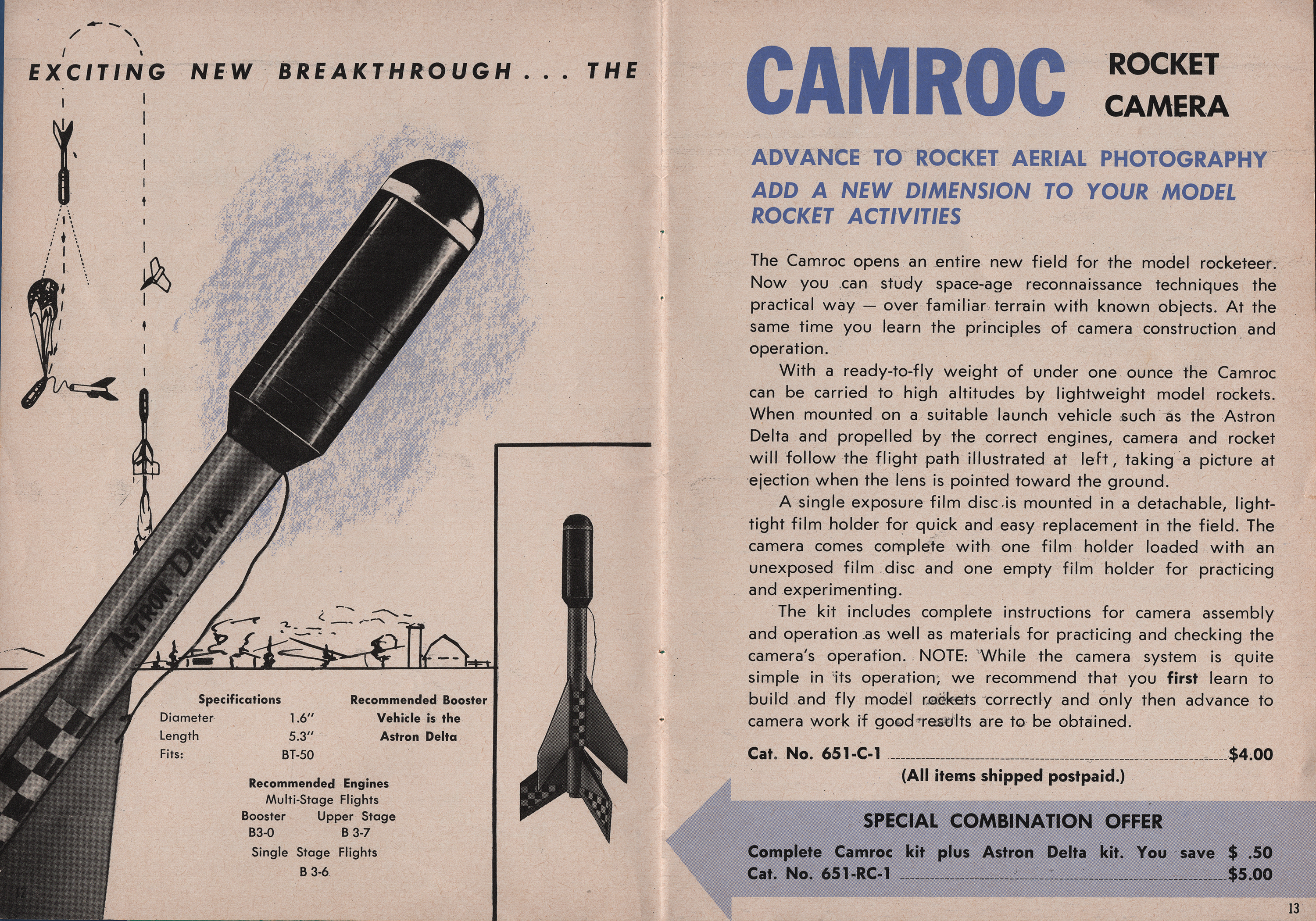
[edit]Cameras and video cameras can be launched on model rockets to take aerial photographs[27][28] in-flight. These photographs can be taken in many ways. Mechanized timers can be used or passive methods may be employed, such as strings that are pulled by flaps that respond to wind resistance. Microprocessor controllers and altimeters can also be used. However, the rocket's speed and motion can lead to blurry photographs, and quickly changing lighting conditions as the rocket points from ground to sky can affect video quality. Video frames can also be stitched together to create panoramas. As parachute systems can be prone to failure or malfunction, model rocket cameras need to be protected from impact with the ground.
The first commercially available system was the Estes CAMROC[29] in 1965. This system used a 1.5 inch round film negative held in a large pill-shaped camera body with the lens facing forwards. It would take a single photograph after apogee as the rocket deployed its parachute. The hobbyist would then send the negatives back to Estes for developing and printing.
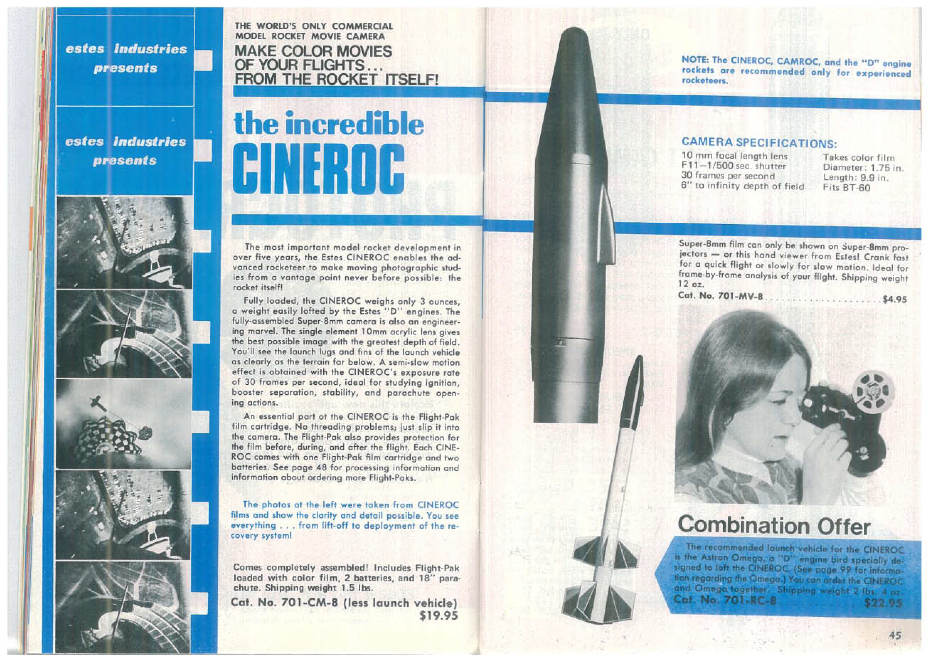
The second system was also released by Estes in 1970. Created by Mike Dorfler, the CINEROC[30] held 20 seconds of Super 8mm film that ran at 30 fps, making for a slow-motion effect. Like the CAMROC negatives, these special movie cartridges needed to be shipped back to Estes to be processed.
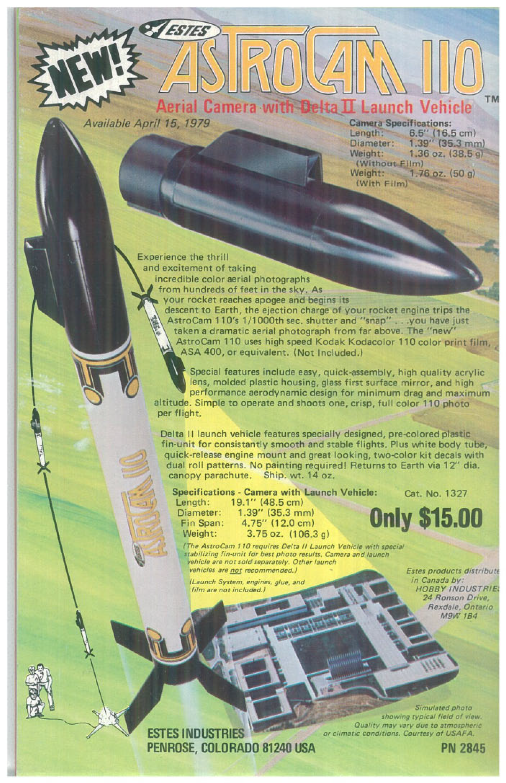
In 1979, Estes released the Astrocam 110,[31] the first single frame camera rocket that took multiple single shot pictures (one per flight) using standard Kodak 110 cartridge film. Unlike its CAMROC predecessor, it could use color film, and did not require sending the film back to Estes for processing. It did require asking the processor to 'flip' the negative before printing, as the camera used a mirror to take its pictures. Otherwise, you were directed to hold prints up to a mirror to see them in the correct attitude. Through the 1980s and into the early 2000s, the Astrocam 110 was revised and updated, originally as a kit where you built the camera, which became one with a pre-built camera, then an Almost Ready to Fly model such as the Astrocam RTF and finally the renamed Snapshot RTF. By the mid 2000s, these models had been retired, as the first digital video cameras started to appear on the market. With Kodak ending 110 film production, only specialty film producers make the ASA400 film needed for these cameras, such as the Austrian based Lomography Company.
In 2005 the Oracle Video Rocket, and in 2007 the AstroVision digital/video camera were released by Estes. Both systems were capable of recording a flight from start to finish, but required downloading after each flight, as expandable memory had not been incorporated into them. The AstroVision did have a snapshot mode, so it could do more than a single flight and take multiple pictures, but movie mode was a single take before needing to be attached to a laptop. Both models were discontinued by 2010. A major reason for this was the advent of the 'Key-Fob camera' - many of which were more powerful, lighter and easier to attach to any rocket, and did not need a specific model to do so, and had expandable memory in the form of Mini SD cards, and were much less expensive. These devices also have the advantage of rechargeable batteries, and since they were built on the same plug-and-play technology Flash Drives use, do not need any extra drivers installed into a computer for them to work. In 2020, Estes brought out a new Key-Fob based camera, which now bears the Astrocam name. As of 2024, two versions can be found - a full rocket kit whose nose cone has a mount for the fob, and the Universal Astrocam, which has the fob along with a holding mount that allows for the camera to ride other models.
In the area of higher powered rocketry, there are also experimental homemade rockets that include onboard video cameras, with multiple methods for shooting videos. One is to transmit a signal down to a receiver, like in the BoosterVision series of cameras. The second method for this is to record it on board and be downloaded after recovery, the method employed by the Estes cameras listed above. (Some experimenters use the Aiptek PenCam Mega for this, the lowest power usable with this method is a C or D Motor).
Instrumentation and experimentation
[edit]Model rockets with electronic altimeters can report and or record electronic data such as maximum speed, acceleration, and altitude. Two methods of determining these quantities are to a) have an accelerometer and a timer and work backwards from the acceleration to the speed and then to the height and b) to have a barometer on board with a timer and to get the height (from the difference of the pressure on the ground to the pressure in the air) and to work forwards with the time of the measurements to the speed and acceleration.
Rocket modelers often experiment with rocket sizes, shapes, payloads, multistage rockets, and recovery methods. Some rocketeers build scale models of larger rockets, space launchers, or missiles.
High-power rocketry
[edit]
As with low-power model rockets, high-power rockets are also constructed from lightweight materials. Unlike model rockets, high-power rockets often require stronger materials such as fiberglass to withstand the higher stresses during flights that often exceed speeds of Mach 1 (340 m/s) and over 3,000 m (9,800 ft) altitude. Because of the potential risk to other aircraft, coordination with proper authorities is often required. For example, in the United States, receiving a Certificate of Authorization or Waiver (COA) from the FAA is required to launch high-power rockets.
High-power rockets are propelled by larger motors ranging from class H to class O, and/or weigh more than 3.3 lbs or 1,500 grams at liftoff. Their motors are almost always reloadable rather than single-use, in order to reduce cost. Recovery and/or multi-stage ignition may be initiated by small on-board computers, which use an altimeter or accelerometer for detecting when to ignite engines or deploy parachutes.
High-power model rockets can carry large payloads, including cameras and instrumentation such as GPS units.
Differences from model rocketry
[edit]A high-power rocket is typically:
- The rocket weighs more than 1,500 grams
- The rocket is rarely made out of metallic and high performance materials, such as Aluminum and carbon fiber, as this is against industry safety standards required by National Association of Rocketry and Tripoli. Instead, fiberglass is often used in order to withstand the rigors of high power motors and flight.
- The motor used contains more than 125 grams of propellant
- The motor used has an impulse of more than 160 Newton-seconds (is an H-class or above) or uses multiple motors with a total impulse of more than 320 Newton-seconds.
- Exact requirements vary from one jurisdiction to another.
See also
[edit]References
[edit]- ^ a b "Model Rocket Safety Code". National Association of Rocketry.
- ^ "Safety". National Association of Rocketry. Retrieved 2012-07-06.
- ^ "Model Rockets". exploration.grc.nasa.gov. National Aeronautics and Space Administration. Archived from the original on 2012-04-10. Retrieved 2012-07-06.
- ^ "Organizational statement of the NAR" (PDF). National Association of Rocketry.
- ^ "Rocket (Black Powder)". PyroGuide. 2010-04-10. Archived from the original on 2007-09-05. Retrieved 2012-07-06.
- ^ Hickam, Homer H (2000). Rocket Boys. Random House Publishers, Inc. ISBN 0-385-33321-8.
- ^ "About Estes". Estes Rockets.com. Retrieved 2012-07-06.
- ^ "Estes Rockets". Estes Rockets. Archived from the original on 2016-03-04. Retrieved 2012-07-06.
- ^ "Great Buys Check Out Other Value Packs". Quest Aerospace. 2009-11-26. Archived from the original on 2016-03-04. Retrieved 2012-07-06.
- ^ "Public Missiles, Ltd. Online Webstore". Publicmissiles.com. Retrieved 2012-07-06.
- ^ "a Rocket Science Resource for Experimental Rocketeers". Arocketry.net. 2005-02-05. Retrieved 2012-07-06.
- ^ "Estes Rockets, Model Rockets, Rocket Engines-Belleville Wholesale Hobby - Custom". dumbledore.com. Archived from the original on 2012-06-30. Retrieved 2012-07-06.
- ^ Radio Control Rocket Glider Safety Code Archived 2006-12-10 at the Wayback Machine
- ^ High-Power Rocket Safety Code Archived 2006-12-05 at the Wayback Machine
- ^ "APCP not an explosive, rules Judge Reggie B. Walton". Planet News. 16 March 2009. Retrieved 9 September 2010.
- ^ "National Association of Rocketry". Archived from the original on 2013-09-28. Retrieved 2013-09-25.
- ^ "Estes Motors : Apogee Rockets, Model Rocketry Excitement Starts Here".
- ^ Penn, Kim and William V. Slaton, Measuring Model Rocket Engine Thrust Curves, The Physics Teacher – December 2010 – Volume 48, Issue 9, pp. 591.
- ^ An Investigation into the Combustion and Performance of Small Solid-Propellant Rocket Motors M.G. Carter. University of New South Wales at the Australian Defence Force Academy. 2008.
- ^ Measuring thrust and predicting trajectory in model rocketry M. Courtney and A. Courtney. Cornell University Library. 2009.
- ^ National Association of Rocketry web site: "National Association of Rocketry | NAR Certified Motors". Archived from the original on 2006-08-13. Retrieved 2006-07-29.
- ^ "Pro-X - A better way to fly". Retrieved 5 July 2012.
- ^ "Pro29® high power rocket motor reload kits". Retrieved 5 July 2012.
- ^ "BPS.Space". BPS.Space. Retrieved 2022-05-04.
- ^ I Landed A Model Rocket Like SpaceX, retrieved 2022-08-02
- ^ LLL Landing Test 8 Raw, retrieved 2023-06-06
- ^ "Video Camera on Model Rocket". Teamten.com. 2011-06-05. Retrieved 2012-07-06.
- ^ "Cameras On Model Rockets". 321rockets.com. Retrieved 2012-07-06.
- ^ "Cat No 651-CR-1".
- ^ "Cat No 701-CM-8".
- ^ "est1327".
External links
[edit]| Products |  | |
|---|---|---|
| Materials | ||
| Scales | ||
| Related topics | ||
Model rocket
View on GrokipediaDefinition and Principles
Core Components and Design Basics
A model rocket's core components form a modular assembly optimized for structural support, aerodynamic performance, initial launch guidance, and post-flight recoverability. These include the nose cone, body tube, fins, motor mount with centering rings, recovery system, and launch lugs, each fulfilling distinct roles while allowing interchangeable parts of standard sizes for straightforward construction and maintenance.[10][11] The nose cone serves as the forward aerodynamic fairing, parting airflow to minimize drag during ascent and often housing part of the recovery system. It typically features shapes like ogive or parabolic for subsonic flight efficiency, constructed from molded plastic for durability and light weight.[12][13] The body tube provides the primary cylindrical structure, enclosing the motor mount and recovery elements while transmitting forces from thrust to the airframe. Standard tubes use spiral-wound kraft paper cardboard for basic models or phenolic-impregnated composites for enhanced strength, offering up to five times the compression resistance of plain cardboard.[14][15] Fins, usually three or four in number, attach to the aft body tube to impart rotational stability via torque from differential drag. They prioritize low mass, employing balsa wood for its favorable strength-to-weight ratio in low-power designs or injection-molded plastic for precision and resilience.[16][17] The motor mount, a smaller-diameter tube within the body, secures the propulsion unit axially, often with a retention hook or clip to prevent premature ejection. Centering rings, typically fiberboard or plywood, position this mount concentrically inside the body tube, ensuring alignment and distributing ejection forces evenly.[18][19] The recovery system deploys at apogee to decelerate descent, commonly comprising a parachute or streamer connected via shock cord to the nose cone and body, preventing damage upon landing. This setup, integrated modularly, separates the rocket into recoverable segments.[20] Launch lugs, short straw-like tubes affixed to the body near the center of gravity, slide over the launch rod to constrain initial motion, providing rail-like guidance until fin-stabilized velocity is achieved.[21][13]Physics of Model Rocket Flight
Model rocket flight adheres to Newton's laws of motion, with thrust generated by the rapid expulsion of combustion products from the solid-propellant engine, invoking the third law's action-reaction principle to accelerate the rocket upward.[22] The first law maintains inertial straight-line motion absent external forces, while disturbances like wind induce aerodynamic corrections via fins. The second law quantifies acceleration as net force divided by mass, where mass decreases as propellant burns, typically reducing by 50-70% during the 1-3 second burn of engines classified A through G by total impulse.[23][24] Four primary forces act on the rocket: thrust (forward during burn), weight (downward, mg where m is mass and g ≈ 9.8 m/s²), drag (rearward, ≈ ½ ρ v² C_d A with ρ air density, v velocity, C_d drag coefficient ~0.3-0.75 for model rockets, A cross-sectional area), and lift (perpendicular to velocity, minimal in axial flight but crucial for stability).[22][25] In powered ascent, thrust peaks at 10-100 N for typical engines, exceeding weight (0.1-5 N) and drag to yield initial accelerations of 10-50 g, propelling velocities to 50-200 m/s at burnout.[26] Post-burnout coasting follows projectile motion under gravity and drag, with altitude peaking at apogee (50-1000 m depending on motor and mass) before descent initiated by ejection charge deploying parachute or streamer, where drag dominates to limit terminal velocity to 5-15 m/s.[27][28] Stability requires the center of gravity (CG, balance point of mass) to lie ahead of the center of pressure (CP, effective point of aerodynamic force application) by 1-2 body diameters (calibers of stability), ensuring restoring moments from fins and body counteract perturbations.[29][30] CP location, calculated via Barrowman equations accounting for nose cone, body, and fin contributions, shifts rearward with increasing Mach number but remains stable for subsonic model rockets (Mach <1).[31] Unstable configurations (CP forward of CG) result in erratic tumbling, while over-stability (>3 calibers) induces weather-cocking into wind.[32] Trajectory prediction integrates these forces numerically, as analytical solutions neglect variable thrust and mass; simulations validate against altimeter data showing coast phase drag reducing apogee by 10-20% versus vacuum models.[33][34]History
Early Origins and Pioneers
The conceptual foundations of model rocketry emerged from the experimental rocketry of the early 20th century, particularly the work of Robert H. Goddard, who achieved the first successful liquid-propellant rocket launch on March 16, 1926, in Auburn, Massachusetts, propelling a device to 41 feet using gasoline and liquid oxygen. Goddard's demonstrations of thrust generation and trajectory control, though centered on professional-scale liquid fuels, provided empirical validation of rocket principles that later influenced hobbyists seeking scalable, safer alternatives for recreational use.[35] In the 1930s and 1940s, isolated hobbyist efforts in the United States and Germany involved rudimentary solid-fuel constructions, often repurposing black powder from fireworks or salvaged military components amid heightened interest from World War II rocketry advancements like the German Aggregat-4 (V-2) missile. These pre-commercial attempts emphasized individual ingenuity but were plagued by the instability of unregulated propellants, resulting in frequent combustion irregularities, structural failures, and documented injuries from explosions—contrasting idealized narratives of effortless invention with the causal reality of trial-and-error hazards absent standardized testing. Wartime restrictions and material scarcity further limited systematic development, confining most activity to ad hoc garage-scale experiments rather than organized pursuits. A critical transition occurred in 1953 when G. Harry Stine, an engineer at the Navy's Point Mugu missile range, engineered the first viable black-powder model rocket motor, prioritizing consistent burn rates and integrated recovery mechanisms to mitigate explosion risks inherent in earlier fuels. Stine's design, tested through iterative flights achieving stable altitudes up to several hundred feet, enabled repeatable hobbyist launches without the pervasive failures of homemade alternatives, directly addressing safety deficits through first-principles focus on propulsion controllability. This innovation preceded his establishment of Model Missiles Inc., marking the shift from perilous improvisation to proto-commercial viability.[36]Establishment of Standards and Organizations
The National Association of Rocketry (NAR) was founded in 1957 by G. Harry Stine to promote safe model rocketry practices and establish industry standards, including motor certification protocols that addressed early inconsistencies in engine performance and reliability.[6][37] The organization developed a safety code emphasizing controlled launches, certified engines, and recovery systems, which became foundational for hobbyists and influenced regulatory acceptance.[37] In 1960, Estes Industries began mass-marketing pre-packaged model rocket kits and engines, making the hobby accessible to broader audiences while adhering to emerging safety guidelines; this commercialization supported millions of launches by standardizing components like igniters and parachutes.[38] Concurrently, the National Fire Protection Association (NFPA) formalized NFPA 1122, Code for Model Rocketry, in the 1960s, specifying requirements for construction, propulsion limits (e.g., up to 125 grams of propellant), launch site dimensions, and operator qualifications to mitigate risks such as uncontrolled fires or structural failures. The Tripoli Rocketry Association emerged in 1964 as a high school science club in Pennsylvania, evolving into a organization focused on high-power rocketry beyond NAR's initial low-thrust scope, with its own certification for motors exceeding standard model limits.[39] These entities collectively enabled widespread adoption, achieving over 500 million safe flights by the late 20th century through enforced testing—NAR alone certified motors via static tests for thrust consistency and ejection reliability—while rare early issues like variable burn rates were resolved via iterative standards.[37][39]Evolution and Recent Developments
Since the early 2000s, model rocketry has incorporated electronic payloads for enhanced flight analysis, with digital altimeters becoming widespread by the 2010s to log metrics such as apogee altitude, acceleration, and velocity.[40] These devices, often barometric-based, provide empirical data that allows builders to validate simulations and refine designs, though their accuracy diminishes above 30,000 feet due to pressure sensor limitations, necessitating complementary accelerometers for high-altitude flights.[41] GPS trackers, introduced commercially around the same period, further enable recovery of drifted rockets by transmitting real-time coordinates via systems like the Eggfinder or Featherweight trackers, reducing loss rates in open fields but adding weight and battery dependencies that can impact beginner stability margins.[42][43] Additive manufacturing via 3D printing emerged as a key customization tool in the 2010s, enabling rapid prototyping of airframes, fins, and nose cones with materials like PLA or PETG, which offer design flexibility unattainable with traditional balsa or cardboard kits.[44] Commercial offerings, such as Estes' Orion 3D Rocket Kit launched in the mid-2010s, integrate printed components with standard engines, allowing hobbyists to iterate on aerodynamics while weighing trade-offs like increased mass—often 20-50% heavier than wood equivalents—against benefits in complex geometries for high-performance variants.[45] Empirical tests confirm viability for low-to-mid power flights, but structural integrity under thrust requires reinforced filaments to avoid delamination.[46] From 2020 onward, integrations like smartphone app-controlled igniters via Bluetooth or ESP32 modules have streamlined launches, permitting remote arming and ignition from distances exceeding 100 feet, as demonstrated in open-source Android-based systems.[47] Sustainability efforts include biodegradable wadding alternatives to tissue paper, such as cellulose-based materials that decompose without residue, addressing environmental concerns in frequent launches.[48] These developments tie into STEM education, with kits emphasizing data logging for curriculum applications, though advanced electronics introduce unnecessary complexity for novices by demanding programming and calibration skills over basic mechanical reliability. The global model rocket market has expanded at a compound annual growth rate of approximately 6.6%, projected to reach $1.74 billion by 2029, driven by accessible tech and youth engagement rather than unsubstantiated hype.[49][50]Propulsion Systems
Motor Types and Classification
Model rocket motors primarily utilize two chemical propellant types: black powder and composite formulations based on ammonium perchlorate composite propellant (APCP). Black powder motors employ a refined form of traditional gunpowder, consisting of potassium nitrate as the oxidizer, combined with charcoal and sulfur, cast into single-use cardboard casings with clay nozzles and delay charges for recovery deployment.[51] These motors dominate low- to mid-power applications, typically spanning impulse classes from 1/2A to G, and are designed for disposable use in basic model rocketry.[52] In contrast, APCP motors incorporate ammonium perchlorate as the oxidizer, aluminum powder as fuel, and a polymeric binder like hydroxyl-terminated polybutadiene (HTPB), yielding higher combustion temperatures—often exceeding 2,500°C in the gas phase—and enabling greater specific impulses compared to black powder, which supports sustained higher-thrust profiles for more demanding flights.[53] This hotter, more energetic burn in APCP facilitates impulses beyond G-class, though such motors still require careful handling due to increased thermal stresses on motor hardware.[54] Structurally, motors are categorized as single-use or reloadable. Single-use motors, common in both propellant types for entry-level rocketry, feature pre-loaded, sealed casings that are expended after flight, prioritizing simplicity and cost-effectiveness for beginners.[55] Reloadable systems, predominantly APCP-based, involve reusable metal or composite cases filled with custom propellant grains, liners, and nozzles, allowing hobbyists to tailor performance for high-power rocketry (HPR) starting at H-impulse levels; these demand greater expertise in assembly to avoid inconsistencies like voids in propellant grains that could compromise burn uniformity.[56] Classification hinges on certification status, with the National Association of Rocketry (NAR) and Tripoli Rocketry Association (TRA) establishing standards via static testing protocols under NFPA 1122 for low-power motors (up to G-class) and NFPA 1127 for HPR.[9] Certified motors undergo rigorous qualification, including thrust curve verification from at least three samples to ensure reproducibility and absence of defects, permitting unrestricted use by hobbyists compliant with safety codes.[7] Experimental or research motors, often amateur-fabricated variants of composite propellants, lack this certification and are restricted to designated research launches under NAR/TRA oversight, as they carry elevated risks of anomalies such as ignition failures or structural failures from untested formulations.[57] Safety data indicate that manufacturing defects, like uneven propellant density leading to partial misfires or delayed ignitions, occur infrequently in certified products—mitigated by standardized production and pre-flight inspections—but experimental motors amplify these hazards due to variability in homemade components, underscoring the empirical value of certification in maintaining low incident rates across organized rocketry.[58]| Propellant Type | Typical Power Range | Key Advantages | Safety Considerations |
|---|---|---|---|
| Black Powder | 1/2A to G | Simple, low-cost single-use; stable at room temperature | Lower energy reduces CATO risk; defects mainly from casing integrity |
| APCP Composite | C and above (esp. HPR) | Higher impulse and thrust; reloadable options | Hotter burn demands robust casings; certification critical for grain uniformity to prevent misfires |
Nomenclature and Performance Metrics
The nomenclature for model rocket motors follows a standardized system established by the National Association of Rocketry (NAR) and adopted by manufacturers to denote key performance characteristics. The designation consists of a letter prefix indicating the total impulse class, followed by a numeric indicator of approximate average thrust in Newtons, and optionally a hyphenated number representing the delay duration in seconds before ejection charge ignition. For example, a B6-4 motor belongs to the B total impulse class (2.5–5.00 N·s), delivers an average thrust of approximately 6 N, and includes a 4-second delay.[59][60] Total impulse, denoted in Newton-seconds (N·s), quantifies the overall energy output as the time integral of thrust force over the burn duration and defines the motor class via logarithmic scaling where each subsequent letter roughly doubles the impulse range:| Class | Total Impulse Range (N·s) |
|---|---|
| 1/4A | 0.00–0.63 |
| 1/2A | 0.63–1.25 |
| A | 1.25–2.50 |
| B | 2.50–5.00 |
| C | 5.00–10.00 |
| D | 10.00–20.00 |
| E | 20.00–40.00 |
| F | 40.00–80.00 |
| G | 80.00–160.00 |