Hubbry Logo
RadiatorRadiatorMain
Open search
Radiator
Community hub
Radiator
logo
8 pages, 0 posts
0 subscribers
Be the first to start a discussion here.
Radiator
Radiator
from Wikipedia
Water-air convective cooling radiator, made from aluminium, from a 21st-century car

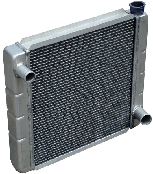
A radiator is a heat exchanger used to transfer thermal energy from one medium to another for the purpose of cooling and heating. The majority of radiators are constructed to function in cars, buildings, and electronics.

A radiator is always a source of heat to its environment, although this may be for either the purpose of heating an environment, or for cooling the fluid or coolant supplied to it, as for automotive engine cooling and HVAC dry cooling towers. Despite the name, most radiators transfer the bulk of their heat via convection instead of thermal radiation.[citation needed]

History

[edit]

The Roman hypocaust is the early example of a type of radiator for building space heating. Franz San Galli, a Prussian-born Russian businessman living in St. Petersburg, is credited with inventing the heating radiator around 1855,[1][2] having received a radiator patent in 1857,[3] but American Joseph Nason and Scot Rory Gregor developed a primitive radiator in 1841[4] and received a number of U.S. patents for hot water and steam heating.[4]

Radiation and convection

[edit]
A cast iron convector radiator from 1904

Heat transfer from a radiator occurs by two mechanisms: thermal radiation and convection into flowing air or liquid. Conduction is not normally a major source of heat transfer in radiators. A radiator may even transfer heat by phase change, for example, drying a pair of socks. In practice, the term "radiator" refers to any of a number of devices in which a liquid circulates through exposed pipes (often with fins or other means of increasing surface area). The term "convector" refers to a class of devices in which the source of heat is not directly exposed.

To increase the surface area available for heat exchange with the surroundings, a radiator will have multiple fins, in contact with the tube carrying liquid pumped through the radiator. Air (or other exterior fluid) in contact with the fins carries off heat. If air flow is obstructed by dirt or damage to the fins, that portion of the radiator is ineffective at heat transfer.

Heating

[edit]
Type 21 Convector Radiator
A panel convector radiator, typical of a standard central heating system in the UK

Radiators are commonly used to heat buildings on the European continent. In a radiative central heating system, hot water or sometimes steam is generated in a central boiler and circulated by pumps through radiators within the building, where this heat is transferred to the surroundings.

In some countries, portable radiators are common to heat a single room, as a safer alternative to space heater and fan heater.

Heating, ventilation, and air conditioning

[edit]

Radiators are used in dry cooling towers and closed-loop cooling towers for cooling buildings using liquid-cooled chillers for heating, ventilation, and air conditioning (HVAC) while keeping the chiller coolant isolated from the surroundings.

Engine cooling

[edit]
Car engine bay, with radiator in front
Auto radiators with double grids of tubes: staggered grids on the left, parallel grids on the right

Radiators are used for cooling internal combustion engines, mainly in automobiles but also in piston-engined aircraft, railway locomotives, motorcycles, stationary generating plants and other places where heat engines are used (watercrafts, having an unlimited supply of a relatively cool water outside, usually use the liquid-liquid heat exchangers instead).

To cool down the heat engine, a coolant is passed through the engine block, where it absorbs heat from the engine. The hot coolant is then fed into the inlet tank of the radiator (located either on the top of the radiator, or along one side), from which it is distributed across the radiator core through tubes to another tank on the opposite end of the radiator. As the coolant passes through the radiator tubes on its way to the opposite tank, it transfers much of its heat to the tubes which, in turn, transfer the heat to the fins that are lodged between each row of tubes. The fins then release the heat to the ambient air. Fins are used to greatly increase the contact surface of the tubes to the air, thus increasing the exchange efficiency. The cooled liquid is fed back to the engine, and the cycle repeats. Normally, the radiator does not reduce the temperature of the coolant back to ambient air temperature, but it is still sufficiently cooled to keep the engine from overheating.

This coolant is usually water-based, with the addition of glycols to prevent freezing and other additives to limit corrosion, erosion and cavitation. However, the coolant may also be an oil. The first engines used thermosiphons to circulate the coolant; today, however, all but the smallest engines use pumps.[5]

Up to the 1980s, radiator cores were often made of copper (for fins) and brass (for tubes, headers, and side-plates, while tanks could also be made of brass or of plastic, often a polyamide). Starting in the 1970s, use of aluminium increased, eventually taking over the vast majority of vehicular radiator applications. The main inducements for aluminium are reduced weight and cost.[citation needed]

Since air has a lower heat capacity and density than liquid coolants, a fairly large volume flow rate (relative to the coolant's) must be blown through the radiator core to capture the heat from the coolant. Radiators often have one or more fans that blow air through the radiator. To save fan power consumption in vehicles, radiators are often behind the grille at the front end of a vehicle. Ram air can give a portion or all of the necessary cooling air flow when the coolant temperature remains below the system's designed maximum temperature, and the fan remains disengaged.[citation needed]

Electronics and computers

[edit]
A passive heatsink on a motherboard

As electronic devices become smaller, the problem of dispersing waste heat becomes more difficult. Tiny radiators known as heat sinks are used to convey heat from the electronic components into a cooling air stream. Heatsinks do not use water, rather they conduct the heat from the source. High-performance heat sinks have copper to conduct better. Heat is transferred to the air by conduction and convection; a relatively small proportion of heat is transferred by radiation owing to the low temperature of semiconductor devices compared to their surroundings.

Radiators are also used in liquid cooling loops for rejecting heat.

Spacecraft

[edit]

Radiators are found as components of some spacecraft. These radiators work by radiating heat energy away as light (generally infrared given the temperatures at which spacecraft try to operate) because in the vacuum of space neither convection nor conduction can work to transfer heat away. On the International Space Station, these can be seen clearly as large white panels attached to the main truss. They can be found on both crewed and uncrewed craft.[6]

See also

[edit]

References

[edit]
Revisions and contributorsEdit on WikipediaRead on Wikipedia
from Grokipedia
A radiator is a that transfers from one fluid to another, most commonly used to dissipate heat from hot liquids like in engines or to emit heat from or hot water into indoor spaces for warming buildings. In automotive applications, it functions as an air-to-liquid device where engine absorbs heat from and circulates through finned tubes, releasing the excess into airflow via to maintain optimal operating temperatures and prevent component damage. For heating purposes, radiators connect to boiler systems that produce or hot water, distributing the fluid through to units where heat radiates and convects into rooms, with steam systems operating at higher temperatures (around 215°F or more) compared to hot water systems (typically 140–180°F). Common types include cast-iron column radiators for traditional heating, known for their durability and high output; modern panel radiators, which offer compact designs with enhanced via integrated fins; and convectors, which use hot water circulation along room perimeters for even distribution. In vehicles, radiators vary by design—such as downflow or crossflow configurations—to optimize and cooling , often augmented by electric fans and thermostats that regulate flow based on thresholds. These devices, essential since the mid-19th century for centralized heating and early 20th-century automobiles, continue to evolve with materials like aluminum for lighter weight and better corrosion resistance in modern applications.

Principles of Operation

Heat Transfer Mechanisms

A radiator functions as a that transfers from a hotter medium, typically a , to a cooler one, such as air, enabling efficient dissipation of heat in various systems. The primary mechanisms of heat transfer in a radiator are conduction, convection, and radiation. Conduction occurs through the solid components of the radiator, such as tubes and fins, where heat flows due to molecular vibrations and collisions without bulk motion of the material. This process is governed by Fourier's law, expressed as the heat flux q=kTq = -k \nabla T, where qq represents the heat flux, kk is the thermal conductivity of the material, and T\nabla T is the temperature gradient. High-conductivity materials like (k400k \approx 400 W/m·K) or aluminum (k237k \approx 237 W/m·K) are commonly used to reduce thermal resistance during conduction, as they facilitate rapid heat spreading from the hot fluid to the outer surfaces. Convection transfers heat from the radiator's surface to the surrounding fluid, either through natural driven by density differences or forced enhanced by fans or pumps. This mechanism follows , given by q=hA(TsT)q = h A (T_s - T_\infty), where hh is the convective , AA is the surface area, TsT_s is the surface , and TT_\infty is the ambient fluid . involves the emission of as electromagnetic waves from the surface, becoming more prominent at elevated temperatures, though it often plays a secondary role compared to conduction and in typical radiator designs. To optimize heat transfer efficiency, radiator designs emphasize maximizing surface area AA while minimizing flow resistances, often through the incorporation of fins that extend the contact area for without excessively increasing conduction path lengths. geometry, such as plate or pin configurations, is tailored to balance added convective benefits against the fin's own thermal resistance, as determined by material properties and fluid flow conditions. The overall heat transfer rate QQ in a radiator integrates these mechanisms and is commonly calculated using Q=UAΔTlmQ = U A \Delta T_{lm}, where UU is the overall encapsulating combined resistances from conduction, , and , and ΔTlm\Delta T_{lm} is the log mean temperature difference between the inlet and outlet fluids. This formulation provides a practical means to evaluate radiator performance across diverse operating conditions.

Radiation and Convection

Thermal radiation in radiators involves the emission of electromagnetic waves, primarily in the infrared spectrum, from the heated surface to its surroundings, independent of any intervening medium. This process is governed by the Stefan-Boltzmann law, which quantifies the net radiative qq as q=εσ(T4Tsur4)q = \varepsilon \sigma (T^4 - T_{\text{sur}}^4), where ε\varepsilon is the surface (ranging from 0 to 1), σ=5.67×10⁸\sigma = 5.67 \times 10^{-8} W/m²K⁴ is the Stefan-Boltzmann constant, TT is the absolute temperature of the radiator surface in , and TsurT_{\text{sur}} is the absolute temperature of the surroundings. In typical air-filled or liquid-cooled radiators operating at room temperatures, convection dominates the heat transfer process due to the movement of air or over the surface, while contributes a smaller share of 10-20% of the total output. For instance, in residential panel radiators with metal fins, the radiative component is approximately 20%, with accounting for the majority through natural or forced . At an of 60°C, a standard home radiator delivers about 80% of its via , highlighting the synergy where provides supplementary transfer without relying on motion. The combined efficiency of radiation and convection in radiators is influenced by key factors such as surface and airflow patterns around extended surfaces like fins. High-emissivity surfaces, such as painted or matte finishes (ε ≈ 0.9), enhance total heat output by up to 17% compared to low-emissivity polished surfaces (ε ≈ 0.1), while also indirectly boosting by elevating the surface temperature and promoting . Airflow patterns, driven by natural or fans, are critical for ; rough or finned surfaces increase local velocities and , improving convective coefficients but potentially shading radiative paths if fins are too dense. Design trade-offs in radiator construction often involve balancing these mechanisms through fin spacing and geometry. Increasing fin spacing enhances convective by reducing resistance and allowing better circulation, potentially raising the overall without excessive material use. Conduction within the radiator material supports this interplay by distributing heat evenly to the emitting surfaces, though it plays a minor role in the external transfer.

Historical Development

Early Inventions

The earliest precursors to modern radiators can be traced to ancient heating systems that relied on to distribute warmth. In the , the system, developed around the 1st century BCE, utilized underfloor channels to circulate hot air from a furnace, effectively heating rooms through conduction and without direct from visible surfaces. This innovative approach was widely applied in public baths and private villas, demonstrating an early understanding of centralized heat distribution. By the , advancements in stove design began to incorporate radiant elements, paving the way for more efficient heating devices. In , experimented with a "mattress" radiator in 1784, consisting of a flat sheet-iron box designed to enhance radiant heat emission from a hot-water or source. Earlier, in the American colonies, Benjamin Franklin's Fireplace, patented in 1741, featured a cast-iron with extended surfaces to radiate heat more effectively into rooms, addressing the inefficiencies of open . In the mid-19th century, steam heating experiments marked a significant step toward practical radiator systems in the United States. Joseph Nason, an engineer who trained in London under hot-water heating pioneer Angier Perkins, returned to Boston around 1841 and began installing steam systems, including the first known U.S. application in the counting-room of Middlesex Mill in Lowell, Massachusetts, circa 1842. By the 1850s, Nason advanced steam technology further, designing the heating and ventilating system for the U.S. Capitol in 1855 using low-pressure steam coils made from wrought-iron pipes. His innovations, including globe valves and tapered pipe threads, facilitated reliable steam distribution and earned him credit for popularizing the term "radiator." Concurrently, the concept of the modern heating radiator emerged in . In 1855, Franz San Galli, a Prussian-born entrepreneur based in St. Petersburg, invented the first cast-iron radiator for a system, initially dubbing it a "" to combat the region's harsh winters. San Galli secured a for his design by 1857, which featured interconnected cast-iron sections for improved and durability. Early radiators predominantly used as the primary material due to its thermal retention and structural strength, allowing for the casting of complex finned sections that maximized surface area for heat emission. However, these initial designs faced challenges, including susceptibility to internal from water impurities and high manufacturing costs stemming from labor-intensive molding and assembly processes. Despite these drawbacks, 's made it the standard for early 19th-century installations, influencing the toward more refined heating solutions.

19th and 20th Century Advancements

In the 1830s, Angier March Perkins pioneered high-pressure hot-water systems in , utilizing small-bore wrought-iron to circulate heated to elevated temperatures, marking a significant advancement over earlier low-pressure designs. This innovation enabled more efficient heat distribution in buildings and gained widespread adoption across by the late , with installations in prominent structures such as public institutions and large residences, facilitating the transition from localized stoves to centralized systems. By the 1880s, cast-iron sectional radiators had become standard, allowing for modular assembly and improved heat emission through increased surface area compared to simple pipe coils. The early saw the introduction of finned-tube radiators, which enhanced by incorporating fins to expand the effective surface area by approximately 5 to 10 times relative to plain tubes. By the 1930s, pressurized cooling systems were developed for engines, employing sealed caps to maintain higher operating pressures (typically 7-15 psi), thereby raising the of and preventing in demanding conditions. The World Wars profoundly influenced radiator technology, as ramped up for military vehicles, standardizing designs like tubular cores for tanks and to meet wartime demands for durability and rapid manufacturing. This wartime acceleration led to postwar refinements, including more robust automotive radiators by the that incorporated lessons from high-stress applications. , building codes in the began mandating more efficient heating systems, such as convection-enhanced baseboard radiators introduced in the early , which promoted uniform air circulation and reduced energy waste in residential and commercial settings.

Building Heating Applications

Residential Radiators

Residential radiators are essential components in hydronic heating systems for homes, primarily utilizing hot water or circulated from a central to provide warmth through and . Common types include column radiators, valued for their ornamental design and retention in traditional settings; panel radiators, typically constructed from compact or aluminum sheets for modern, space-efficient installations; and convector units, such as models, which feature fins to enhance air circulation and rapid distribution. These designs cater to domestic needs, balancing , output, and ease of integration into home layouts. In operation, hot water systems heat water in a boiler to 140–180°F (60–82°C) and use a pump to circulate it through pipes to the radiators, where the heated metal surfaces emit warmth into the room before the cooled water returns to the boiler; steam systems, conversely, rely on natural pressure from boiling water without pumps, though they are less common in newer homes due to inefficiency. Typical heat output ratings for residential units range from 500–600 BTU/hr per linear foot for baseboard convectors at standard water temperatures, varying by material and design to match room demands. Installation considerations emphasize placement for optimal performance: wall-mounted options, like panel radiators, conserve floor space and promote even heat distribution, while freestanding column types offer flexibility for room reconfiguration. systems, incorporating individual thermostats per radiator or room, enhance multi-room efficiency by allowing targeted , reducing waste in unused areas. Integration with programmable thermostats further optimizes operation by automating adjustments based on occupancy. Efficiency in residential radiators hinges on proper sizing via BTU calculations, which account for room volume, insulation levels, and external factors—typically 4–5 BTU per for standard bedrooms—to ensure adequate heating without oversizing. Modern low-temperature models, designed for flows as low as 130–140°F (55–60°C), achieve system efficiencies exceeding 90% when paired with condensing boilers, as they allow fuller heat extraction and minimize energy loss; these models are increasingly compatible with heat pumps for low-carbon heating as of 2025. Maintenance practices are crucial for longevity and performance: bleeding air valves annually or when cold spots appear removes trapped air, promoting even heating and preventing boiler strain. Corrosion prevention involves adding chemical inhibitors to the system water to protect metal components from , especially in older units. Common issues like uneven heating often stem from imbalanced valves or sediment buildup, resolvable by professional balancing or flushing.

Commercial and Institutional Systems

In commercial and institutional settings such as offices, schools, and hospitals, radiator systems are engineered for high-capacity heating to maintain across expansive areas often exceeding 10,000 square feet, utilizing BTU load calculations that typically range from 30 to 60 BTUs per square foot based on insulation, , and factors. These systems incorporate multi-zone controls to enable independent in different building sections, optimizing energy use by adjusting heat delivery only to occupied zones and providing significant energy savings compared to single-zone setups. Unlike residential applications, which focus on smaller, decorative units, commercial designs prioritize and integration with systems for precise . Common types include trench radiators installed in floor recesses for perimeter heating, which distribute warmth evenly along exterior walls without obstructing space; baseboard convectors that run along walls to enhance in corridors and open areas; and high-output fan-assisted units that boost for rapid heating in large volumes, achieving up to three times the output of passive radiators at low water temperatures. Materials emphasize durability in high-traffic environments, with construction providing resistance and exceeding 20-30 years under continuous use, while units can deliver capacities up to 400,000 BTU/hr to support entire wings or floors. Energy efficiency in these systems aligns with Standard 90.1, which mandates minimum performance for HVAC components including hydronic heating, promoting variable flow pumps that adjust circulation rates to match demand and achieve 10-15% savings in pumping energy; these systems are also increasingly integrated with heat pumps for sustainable operation as of . In hospital applications, case studies highlight hygienic, low-noise designs like specialized panel radiators with smooth, cleanable surfaces to minimize infection risks and support patient recovery, as implemented in facilities prioritizing sterile environments.

Automotive and Engine Cooling

Internal Combustion Engine Radiators

Internal combustion engine radiators serve as essential heat exchangers in liquid-cooled systems for and diesel engines, dissipating excess generated during to prevent overheating and maintain optimal performance. The core of the radiator consists of a series of flat tubes through which hot flows, surrounded by thin fins that increase surface area for air exposure and enhance convective . Header tanks, also known as inlet and outlet tanks, are positioned at the ends of the core to distribute and collect the coolant, typically made from durable in modern designs for weight reduction and resistance. The , integrated into the coolant circuit near the engine, regulates flow by opening at around 82-88°C to allow hot coolant to enter the radiator only when necessary, ensuring rapid engine warm-up and efficient temperature control. A fan shroud encases the cooling fan, directing airflow uniformly across the entire radiator core to maximize cooling , particularly at low speeds or conditions. Traditional radiator cores often used for tubes due to its thermal conductivity and , paired with aluminum fins for lightweight heat dissipation, though contemporary designs predominantly employ all-aluminum construction for better resistance and reduced weight. The cycle in these systems relies on a pressurized mixture of and (typically 50/50 ) to raise the above 110°C and improve properties, circulated by a belt- or electric-driven water pump from the through the radiator. This solution absorbs heat from engine components like the and block, reaching operating temperatures of 90-105°C under load to optimize and emissions. The pressurized system, maintained at 1.0-1.5 bar by the radiator cap, prevents vapor bubble formation that could impair cooling, with the flowing via hoses to the radiator where it releases heat to ambient air before returning to the engine. Heat rejection in the radiator is quantified by the formula Q=m˙cpΔTQ = \dot{m} c_p \Delta T, where QQ is the rate (in watts), m˙\dot{m} is the (typically 5-10 kg/s in automotive engines), cpc_p is the of the (approximately 3.8 kJ/kg·K for a water-glycol mix), and ΔT\Delta T is the drop across the radiator (often 10-20°C from inlet to outlet). In engine applications, this determines the required radiator capacity, with typical passenger car engines rejecting 20-50 kW of to the under full load, ensuring the system handles up to 30-35% of total fuel energy losses. Common radiator designs include downflow and crossflow configurations, with downflow directing coolant vertically from top to bottom tanks for straightforward gravity-assisted flow, suitable for older layouts. Crossflow designs, prevalent in modern transverse-engine vehicles, route coolant horizontally across the core, promoting more even temperature distribution and improved airflow efficiency, especially with low-profile frontal areas. Overheating issues in these radiators often stem from internal clogs due to sediment buildup or degraded , restricting flow and reducing heat dissipation efficiency. Radiator failures, such as worn seals or incorrect ratings, can lead to coolant loss through or external leaks, compromising system pressurization. Diagnostics typically involve testing the system to 1.2-1.5 times the rating (e.g., 15-20 psi) to detect leaks or weak points, often using a specialized connected to the radiator filler neck while monitoring for drops in over time. When performing maintenance such as adding coolant, safety precautions must be observed. When adding coolant to a hot engine, wait for it to cool completely—at least 2-3 hours after driving—since opening the cap on a hot engine can cause pressurized coolant to spray out dangerously.

Electric and Hybrid Vehicle Systems

In electric vehicles (EVs), radiators play a critical role in management systems by dissipating from , inverters, and battery packs to maintain optimal operating conditions. Lithium-ion batteries, the storage in EVs, require temperatures between 15°C and 35°C to achieve peak performance, longevity, and , as deviations can accelerate degradation or trigger hazardous events. Liquid-cooled radiators, often integrated into closed-loop circuits, provide uniform temperature distribution across battery cells—limiting variations to under 3–4°C—while handling loads from high-power components like inverters that convert DC to AC for motors. These systems typically employ glycol-water mixtures circulated via pumps to the radiator, where air rejects excess , ensuring operate below 100°C under peak loads. As of 2025, using fluids has been adopted in the first production consumer electric vehicles, marking a milestone in efficient battery management. Hybrid electric vehicles (HEVs) extend this functionality with separate thermal loops for the and , allowing independent control to address differing heat profiles. The battery loop uses dedicated radiators and electric pumps to enable variable flow rates, optimizing circulation based on real-time demands such as or acceleration, which can reduce by up to 30% compared to fixed-flow mechanical pumps. This separation prevents engine heat from compromising battery efficiency, maintaining cell temperatures in the 15–35°C range even during mixed-mode operation. Electric pumps, driven by the vehicle's low-voltage system, provide precise modulation without engine dependency, enhancing overall system responsiveness in models like those from and Ford. Advanced coolants have enhanced radiator performance in EV and HEV systems, particularly dielectric fluids for direct immersion cooling of batteries and electronics. These non-conductive liquids, such as hydrofluoroethers (e.g., 3M Novec series), ensure electrical isolation while achieving heat transfer coefficients of 2–5 kW/m²K in single-phase setups—up to 1,000 times more efficient than air cooling—reducing maximum battery temperatures to around 30°C during fast charging. Phase-change materials (PCMs), integrated with radiator loops, further boost efficiency by absorbing latent heat during phase transitions, offering lightweight thermal buffering that improves energy density and cuts cooling power needs by 20–50% in hybrid systems. Such innovations minimize radiator size while maintaining high dissipation rates, with PCM-enhanced designs showing up to 10°C lower peak temperatures than conventional liquid cooling alone. Post-2010 design innovations have focused on compact, low-profile radiators to optimize and in EVs like Tesla models, integrating them into modular front-end assemblies for streamlined airflow. These aluminum-core units, often with micro-channel fins, achieve thermal efficiencies exceeding 90% by maximizing surface area exposure while reducing frontal area by 20–30% compared to earlier designs. Wide-bandgap semiconductors in inverters further lessen radiator demands, enabling single-loop configurations that consolidate cooling for multiple components and improve vehicle range by 5–10%. Key challenges in these systems include preventing thermal runaway, where exothermic reactions in lithium-ion cells can escalate temperatures beyond 155°C, propagating failure across the pack. Real-time monitoring via embedded sensors—one per cell for internal temperature and impedance—detects precursors like SEI layer breakdown at >85°C, allowing radiator pumps to activate preemptively and vent excess heat. Advanced battery management systems (BMS) integrate these sensors with radiator controls to limit propagation, using phase-change venting and isolated loops to contain incidents in under 10 seconds.

HVAC Systems

Heating Components

In HVAC systems, radiators serve as key heating elements that transfer from a hot fluid, typically or , to the surrounding air through and . Finned-tube coils, integrated into air handlers, facilitate ducted hot air distribution by passing heated air through building spaces via ventilation networks. Standalone hydronic radiators, often panel or column types, provide localized heating in zones without ductwork, relying on circulation to emit directly into rooms. Hydronic distribution systems from central boilers employ one-pipe or two-pipe configurations to deliver heated to radiators. In one-pipe systems, flows sequentially through radiators in series, with cooled mixing back into the supply line, which simplifies installation but limits individual zone control. Two-pipe systems use separate supply and return lines, connecting radiators in parallel for balanced flow and precise temperature regulation across zones. Typical flow rates in these systems range from 2 to 4 gallons per minute (gpm) per ton of heating capacity, ensuring adequate while minimizing energy use. Controls such as thermostatic radiator valves (TRVs) enable individual room modulation by automatically adjusting flow based on setpoint temperatures, preventing overheating and optimizing distribution. These valves can achieve energy savings of approximately 15% in hydronic setups by reducing unnecessary heat delivery in occupied spaces. Modern gas boilers paired with radiators in HVAC heating achieve seasonal efficiency ratings exceeding 90% (AFUE), converting over 90% of fuel input into usable heat while minimizing losses. Radiator sizing in HVAC applications is determined through heat loss calculations, accounting for , , and to match output to . For conditioned spaces, typical requirements range from 25 to 50 British thermal units per hour (BTU/hr) per , depending on and insulation, ensuring comfort without oversizing that could lead to short-cycling and inefficiency.

Cooling and Ventilation Integration

In HVAC systems, evaporator coils primarily function to absorb heat from indoor air to provide cooling and dehumidification. These coils operate by circulating either refrigerants in direct expansion (DX) systems or chilled water typically supplied at 4-7°C in hydronic setups, where the absorbed heat is rejected to outdoor condensers via a refrigeration cycle. As of 2025, systems increasingly use low-global-warming-potential refrigerants such as R-454B in compliance with phase-down regulations. Ventilation integration enhances the efficiency of these evaporator coils by combining them with management to distribute conditioned air throughout a building. In DX systems, evaporator coils handle rates of 400-2000 cubic feet per minute (CFM), facilitating sensible cooling and removal for dehumidification, which is crucial in humid climates to maintain indoor comfort levels below 50-60% relative . Design of these cooling components emphasizes compact, high-efficiency structures, such as multi-row finned coils constructed from tubes and aluminum fins, which are optimized for a low temperature differential () of 5-10°C between the coil surface and entering air in cooling mode. This configuration maximizes while minimizing fan energy use, with coil depths often ranging from 6 to 12 rows to balance pressure drop and performance. Energy recovery ventilators (ERVs) incorporate elements to preheat or precool incoming fresh air using exhaust air streams, transferring both sensible and without mixing airstreams, thereby reducing the cooling load on primary evaporator coils by 20-50% in moderate climates. These s, sealed with refrigerants like R134a, operate passively through evaporation and condensation cycles within the pipes. Compliance with standards such as the International Energy Conservation Code (IECC) ensures that cooling coil systems in HVAC designs meet minimum efficiency requirements for cooling loads, often integrating variable speed fans to modulate airflow and achieve 2 (SEER2) of 14 or higher for residential applications (as of 2025). This approach not only optimizes energy use but also aligns with broader goals of reducing in building operations.

Electronics Cooling

Component-Level Heat Dissipation

Component-level heat dissipation in electronics relies on compact radiators, commonly known as heat sinks, designed to manage thermal loads from individual components such as central processing units (CPUs) and graphics processing units (GPUs). These heat sinks primarily employ , either passive or forced via integrated fans, to transfer heat from the component to the ambient environment. Key designs include pin-fin and straight-fin configurations, often fabricated as aluminum extrusions for their balance of lightweight properties and cost-effectiveness. Pin-fin heat sinks, featuring cylindrical or square protrusions arranged in a grid, outperform straight-fin (plate-fin) designs by enhancing airflow turbulence and increasing surface area exposure, achieving up to 50% lower thermal resistance under identical flow conditions. In contrast, straight-fin heat sinks use parallel plates that direct airflow linearly, offering simpler manufacturing but reduced efficiency in compact spaces where cross-flow is limited. The effectiveness of these heat sinks is quantified by thermal resistance, defined as θ=ΔTQ\theta = \frac{\Delta T}{Q}, where ΔT\Delta T is the temperature difference between the heat sink base and ambient air, and QQ is the dissipation rate. For air-cooled designs attached to CPUs, typical values range from 0.5 to 2 °C/W, depending on fin density, , and size; lower resistances (around 0.2-0.5 °C/W) are achievable with optimized pin-fin arrays under . Attachment to the component is critical and involves thermal interface materials (TIMs) to minimize , such as thermal pastes with conductivities of 5-10 W/m·K that fill microscopic air gaps between the CPU integrated and heat sink base. Mechanical clips or springs ensure uniform pressure (typically 20-30 psi) for optimal contact without damaging the die. Performance metrics highlight the capacity of these radiators to handle modern desktop processors, which generate 100-300 W under load, as seen in high-end i9 and 9 series. Forced air cooling via fans boosts the convective hh to 50-100 W/m²·K, significantly enhancing dissipation compared to natural convection (5-25 W/m²·K) by promoting disruption over fin surfaces. Material selection further optimizes efficiency: bases provide high thermal conductivity of 400 W/m·K for rapid heat spreading from the contact point, while anodized aluminum fins offer an emissivity of approximately 0.85, aiding radiative heat loss in low-airflow scenarios. For scenarios, where power draws can exceed 500 to push clock speeds beyond stock limits, advanced TIMs like liquid metals (e.g., gallium-indium alloys) are employed, offering conductivities up to 70 /m·K to sustain sub-100 °C junction temperatures under extreme loads. These non-polymer TIMs reduce interfacial resistance by nearly an compared to pastes but require careful application to avoid short-circuiting due to their electrical conductivity. Such enhancements enable reliable operation in enthusiast builds, though they demand compatible materials to prevent . Scaling these component-level solutions informs broader system designs, but primary focus remains on discrete thermal management.

System-Level Cooling Solutions

System-level cooling solutions in employ interconnected cooling loops that integrate radiators with pumps, reservoirs, and tubing to manage from multiple components simultaneously, building upon individual heat sinks as foundational elements for . Closed-loop all-in-one (AIO) systems provide a pre-assembled solution featuring radiators typically sized from 120mm to 360mm, integrated pumps, and reservoirs capable of dissipating up to 150-400W for CPU loads in high-performance PCs, depending on fan speed and configuration. Custom loops extend this capability through series or parallel tubing configurations with multiple radiators, often incorporating EKWB-style water blocks for GPUs to achieve balanced flow and enhanced dissipation in overclocked setups. As of 2025, emerging AI workloads with components exceeding 1000W have driven adoption of advanced AIO and custom solutions with larger radiators. In data centers, rear-door heat exchangers function as large-scale radiators, capturing exhaust heat from server racks and transferring it to chilled water loops, handling 10kW to 50kW per rack to support dense AI and workloads. These systems prioritize , with pumps consuming less than 5W at operational speeds to minimize overhead, while () calculations optimize flow rates to 1-2 L/min, ensuring adequate circulation without excessive energy use. Post-2020 trends highlight immersion cooling's rise in data centers, where submerging components in fluids reduces reliance on traditional radiator-based systems by up to 50%, enabling direct rejection and lower infrastructure demands.

Aerospace and Spacecraft Uses

Aircraft Radiators

Aircraft radiators play a in managing dissipation for propulsion systems in , ensuring reliable operation across varying flight conditions from takeoff to high-altitude cruise. In piston-engine aircraft, radiators are typically liquid-cooled systems that circulate , such as glycol-water mixtures, through heat exchangers to reject engine to the airstream. These designs prioritize aerodynamic efficiency to minimize drag while maintaining , particularly in high-performance fighters where excess drag could compromise speed and range. Key configurations include surface coolers, which integrate flat panels into the for direct , and submerged coolant systems, where the radiator core is housed within enclosed ducts to optimize and reduce external profile. A notable example of advanced piston-engine radiator design is the annular radiator in the of , which utilized a submerged glycol radiator within a wing-root duct. This setup incorporated the , where heated exhaust air from the radiator expanded and accelerated, generating forward thrust that offset much of the installation drag, achieving a net propulsive benefit for the overall system. Surface coolers, by contrast, expose channels directly to ram air over wing or fuselage surfaces, simplifying integration but requiring careful placement to avoid structural interference. These systems were essential for liquid-cooled V-12 engines like the Packard Merlin, dissipating up to several hundred kilowatts of heat while preserving the aircraft's sleek profile. In jet-engine aircraft, radiators primarily function as oil coolers mounted in engine nacelles or dedicated ram-air ducts, handling substantial thermal loads from lubrication and accessory systems. These air-cooled heat exchangers use ram air at speeds up to Mach 0.8 to dissipate heat, with capacities typically ranging from 50 to 200 kW in modern high-bypass turbofans, depending on engine size and operating conditions. The design leverages incoming airstream compression for enhanced cooling without additional fans at subsonic speeds, though integration into nacelles demands precise airflow management to prevent hot spots or efficiency losses. Submerged variants route oil through core matrices within the engine bay, further streamlining external aerodynamics. Design challenges in radiators center on balancing heat rejection with minimal aerodynamic penalty, especially at high altitudes where air density decreases significantly. At 30,000 feet, air density drops to approximately 30% of sea-level values, reducing convective cooling effectiveness by up to 70% and necessitating larger core areas or higher velocities. To mitigate drag, installations target incremental drag coefficients below 0.01, achieved through ducted inlets, diffusers, and ejector nozzles that recover and minimize spillage. Variable-pitch fans supplement ram air in low-speed regimes or at altitudes exceeding 30,000 feet, adjusting blade angle to maintain airflow volume against thinning air and enabling efficient operation from ground idle to cruise. These adaptations ensure sustained cooling without excessive power draw from the engine. Materials selection for radiators emphasizes construction, conductivity, and durability under cyclic and aerodynamic stresses. Aluminum alloys dominate due to their low of 2.7 g/cm³ and excellent properties, forming the basis for finned-tube cores in most designs. , with a density of 4.5 g/cm³, offers weight savings in high-temperature zones through superior strength-to-weight ratio and retention of properties up to 550°C, allowing thinner sections despite higher density compared to aluminum. Corrosion-resistant coatings, such as anodized layers or organic composites, protect against glycol degradation and environmental exposure, extending service life in humid or saline conditions. Historically, early jet aircraft like the faced severe cooling challenges with its engines, including turbine blade overheating and short operational life due to inadequate air-cooling provisions in the axial-flow design. These issues stemmed from high thermal stresses in the uncooled turbine sections, limiting engine endurance to mere hours. By the late 1940s, axial-flow advancements incorporated hollow, air-cooled turbine blades and improved compressor efficiencies, resolving overheating and enabling reliable high-altitude performance in subsequent designs.

Spacecraft Thermal Radiators

Spacecraft thermal radiators are essential components of thermal control systems designed to maintain operational temperatures in the vacuum of , where convective cooling is impossible and heat dissipation occurs solely through . These systems rely on deployable panels that reject generated by onboard electronics, propulsion, and scientific instruments into deep . For instance, the International Space Station's (EATCS) employs large, rotating radiator panels to reject up to 70 kW of heat from its coolant loops, ensuring stable temperatures across the orbital laboratory. The panels, organized into Orbital Replaceable Units (ORUs), each measuring approximately 3.1 meters by 13.6 meters, unfold and articulate to optimize exposure away from solar influx, demonstrating the scale required for high-power . Design of these radiators emphasizes materials with tailored to minimize solar absorption while maximizing emission. Optical Solar Reflectors (OSRs), typically second-surface mirrors consisting of a reflective metal layer (such as silver or aluminum) beneath a or fused silica coverglass, are widely used on the sun-facing sides of radiator panels. These coatings achieve low solar absorptivity (α ≈ 0.1) and high thermal (ε ≈ 0.8), resulting in an α/ε ratio below 0.15, which prevents excessive heating from solar radiation while efficiently radiating heat. This selective spectral response allows radiators to operate effectively across the extreme thermal environment of space, where surfaces can fluctuate between -150°C and +120°C depending on and attitude. As of 2025, advancements include improved OSR composites for missions like the , enhancing durability and efficiency. Internal heat transfer within spacecraft thermal systems often incorporates heat pipes to distribute heat evenly to the radiator surfaces. Ammonia-filled heat pipes, favored for their compatibility with aluminum structures and operation in the -50°C to +100°C range, transport 10-100 per pipe via capillary action in grooved wicks, enabling isothermal transport over distances up to several meters. Deployment mechanisms for these radiators typically involve folded panels that expand post-launch using pyrotechnic actuators, stepper motors, or spring-loaded hinges to achieve full surface area in . On the , for example, the Near Infrared Camera and Multi-Object Spectrograph (NICMOS) cooling system features deployable radiator panels connected via a capillary pumped loop, which were extended on-orbit to reject heat, actuated through a combination of mechanical linkages and thermal isolation. Modern advancements integrate radiators with multi-layer sunshields for enhanced cryogenic performance, as seen in the (JWST), launched in 2021. JWST's Integrated Science Instrument Module (ISIM) uses five single-stage cryogenic radiators, positioned behind the five-layer sunshield, to passively cool instruments to below 37 K by rejecting low-temperature heat loads while the sunshield blocks solar input. These honeycomb-structured radiators, coated for optimal , handle the telescope's unique deep-space requirements, maintaining the primary mirror at approximately 40 K through isolated thermal paths. Emerging applications of spacecraft thermal radiators include space-based data centers, which present unique challenges for deployable radiator panels due to high heat loads from computing operations. For a 1 MW system, radiator areas of approximately 1,000–2,000 m² are required, significantly increasing mass and launch costs while complicating reliable deployment mechanisms. These hurdles are being addressed through modular and reusable designs, as well as lightweight materials such as carbon-carbon composites and advanced heat pipes.

References

Add your contribution
Related Hubs
User Avatar
No comments yet.