

Community hub
Recent from talks
Contribute something
Nothing was collected or created yet.
Formwork
View on WikipediaThis article needs additional citations for verification. (May 2018) |


Formwork is molds into which concrete or similar materials are either precast or cast-in-place. In the context of concrete construction, the falsework supports the shuttering molds. In specialty applications formwork may be permanently incorporated into the final structure, adding insulation or helping reinforce the finished structure.
Types
[edit]Formwork may be made of wood, metal, plastic, or composite materials:
- Traditional timber formwork. The formwork is built on site out of timber and plywood or moisture-resistant particleboard. It is easy to produce but time-consuming for larger structures, and the plywood facing has a relatively short lifespan. It is still used extensively where the labour costs are lower than the costs for procuring reusable formwork. It is also the most flexible type of formwork, so even where other systems are in use, complicated sections may use it.
- Engineered Formwork System. This formwork is built out of prefabricated modules with a metal frame (usually steel or aluminium) and covered on the application (concrete) side with material having the wanted surface structure (steel, aluminum, timber, etc.). The two major advantages of formwork systems, compared to traditional timber formwork, are speed of construction (modular systems pin, clip, or screw together quickly) and lower life-cycle costs (barring major force, the frame is almost indestructible, while the covering if made of wood; may have to be replaced after a few - or a few dozen - uses, but if the covering is made with steel or aluminium the form can achieve up to two thousand uses depending on care and the applications). Metal formwork systems are better protected against rot and fire than traditional timber formwork.
- Re-usable plastic formwork. These interlocking and modular systems are used to build widely variable, but relatively simple, concrete structures. The panels are lightweight and very robust. They are especially suited for similar structure projects and low-cost, mass housing schemes. To get an added layer of protection against destructive weather, galvanized roofs will help by eliminating the risk of corrosion and rust. These types of modular enclosures can have load-bearing roofs to maximize space by stacking on top of one another. They can either be mounted on an existing roof, or constructed without a floor and lifted onto existing enclosures using a crane.[citation needed]
- Permanent Insulated Formwork. This formwork is assembled on site, usually out of insulating concrete forms (ICF). The formwork stays in place after the concrete has cured, and may provide advantages in terms of speed, strength, superior thermal and acoustic insulation, space to run utilities within the EPS layer, and integrated furring strip for cladding finishes.
- Stay-In-Place structural formwork systems. This formwork is assembled on site, usually out of prefabricated fiber-reinforced plastic forms. These are in the shape of hollow tubes, and are usually used for columns and piers. The formwork stays in place after the concrete has cured and acts as axial and shear reinforcement, as well as serving to confine the concrete and prevent against environmental effects, such as corrosion and freeze-thaw cycles.
- Flexible formwork. In contrast to the rigid moulds described above, flexible formwork is a system that uses lightweight, high strength sheets of fabric to take advantage of the fluidity of concrete and create highly optimised, architecturally interesting, building forms. Using flexible formwork it is possible to cast optimised structures that use significantly less concrete than an equivalent strength prismatic section,[1] thereby offering the potential for significant embodied energy savings in new concrete structures.
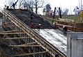
Slab formwork (deck formwork)
[edit]

.jpg)

History
[edit]Some of the earliest examples of concrete slabs were built by Roman engineers. Because concrete is quite strong in resisting compressive loads, but has relatively poor tensile or torsional strength, these early structures consisted of compression-resistant arches, vaults and domes. The most notable concrete structure from this period is the Pantheon in Rome. To mould this structure, temporary scaffolding and formwork or falsework was built in the future shape of the structure. These building techniques were not isolated to pouring concrete, but were and are widely used in masonry construction. Because of the complexity and the limited production capacity of the building material[citation needed], concrete's rise as a favored building material did not occur until the invention of Portland cement and reinforced concrete.
Timber beam slab formwork
[edit]Similar to the traditional method, but stringers and joists are typically replaced with engineered wood beams and supports are replaced with adjustable metal props. This makes this method more systematic and reusable.
Traditional slab formwork
[edit]
On the dawn of the revival of concrete in slab structures, building techniques for the temporary structures were derived again from masonry and carpentry. The traditional slab formwork technique consists of supports out of lumber or young tree trunks, that support rows of stringers assembled roughly 3 to 6 feet or 1 to 2 metres apart, depending on thickness of slab. Between these stringers, joists are positioned roughly 12 inches (30 cm) apart, upon which boards or plywood are placed. The stringers and joists are usually 4 by 4 inch or 4 by 6 inch lumber. The most common imperial plywood thickness is 3⁄4 inch and the most common metric thickness is 18 mm.
Metal beam slab formwork
[edit]Similar to the traditional method, but stringers and joist are replaced with aluminium forming systems or steel beams and supports are replaced with metal props. This also makes this method more systematic and reusable. Aluminum beams are fabricated as telescoping units which allows them to span supports that are located at varying distances apart. Telescoping aluminium beams can be used and reused in the construction of structures of varying size.


Modular slab formwork
[edit]These systems consist of prefabricated timber, steel or aluminum beams and formwork modules. Modules are often no larger than 3 to 6 feet or 1 to 2 metres in size. The beams and formwork are typically set by hand and pinned, clipped, or screwed together. The advantages of a modular system are: does not require a crane to place the formwork, speed of construction with unskilled labor, formwork modules can be removed after concrete sets leaving only beams in place prior to achieving design strength.
Table or flying form systems
[edit]These systems consist of slab formwork "tables" that are reused on multiple stories of a building without being dismantled. The assembled sections are either lifted per elevator or "flown" by crane from one story to the next. Once in position the gaps between the tables or table and wall are filled with temporary formwork. Table forms vary in shape and size as well as their building material, with some supported by integral trusses. The use of these systems can greatly reduce the time and manual labor involved in setting and striking (or "stripping") the formwork. Their advantages are best used by large area and simple structures. It is also common for architects and engineers to design building around one of these systems.

Structure
[edit]A table is built pretty much the same way as a beam formwork but the single parts of this system are connected together in a way that makes them transportable. The most common sheathing is plywood, but steel and fiberglass are used. The joists are either made from timber, engineered lumber (often in the form of I-beams), aluminium or steel. The stringers are sometimes made of wood I-beams but usually from steel channels. These are fastened together (screwed, weld or bolted) to become a "deck". These decks are usually rectangular but can also be other shapes.
Support
[edit]All support systems have to be height adjustable to allow the formwork to be placed at the correct height and to be removed after the concrete is cured. Normally adjustable metal props similar to (or the same as) those used by beam slab formwork are used to support these systems. Some systems combine stringers and supports into steel or aluminum trusses. Yet other systems use metal frame shoring towers, which the decks are attached to. Another common method is to attach the formwork decks to previously cast walls or columns, thus eradicating the use of vertical props altogether. In this method, adjustable support shoes are bolted through holes (sometimes tie holes) or attached to cast anchors.
Size
[edit]The size of these tables can vary from 70 to 1,500 square feet (6.5 to 140 m2). There are two general approaches in this system:
- Crane handled: this approach consists of assembling or producing the tables with a large formwork area that can only be moved up a level by crane. Typical widths can be 15, 18 or 20 feet, or 5 to 7 metres, but their width can be limited, so that it is possible to transport them assembled, without having to pay for an oversize load. The length might vary and can be up to 100 feet (or more) depending on the crane capacity. After the concrete is cured, the decks are lowered and moved with rollers or trolleys to the edge of the building. From then on the protruding side of the table is lifted by crane while the rest of the table is rolled out of the building. After the centre of gravity is outside of the building the table is attached to another crane and flown to the next level or position.
This technique is fairly common in the United States and east Asian countries. The advantages of this approach are the further reduction of manual labour time and cost per unit area of slab and a simple and systematic building technique. The disadvantages of this approach are the necessary high lifting capacity of building site cranes, additional expensive crane time, higher material costs and little flexibility.

- Crane fork or elevator handled:
By this approach the tables are limited in size and weight. Typical widths are between 6 and 10 feet (1.8 and 3.0 m), typical lengths are between 12 and 20 feet (3.7 and 6.1 m), though table sizes may vary in size and form. The major distinction of this approach is that the tables are lifted either with a crane transport fork or by material platform elevators attached to the side of the building. They are usually transported horizontally to the elevator or crane lifting platform singlehandedly with shifting trolleys depending on their size and construction. Final positioning adjustments can be made by trolley. This technique enjoys popularity in the US, Europe and generally in high labor cost countries. The advantages of this approach in comparison to beam formwork or modular formwork is a further reduction of labor time and cost. Smaller tables are generally easier to customize around geometrically complicated buildings, (round or non rectangular) or to form around columns in comparison to their large counterparts. The disadvantages of this approach are the higher material costs and increased crane time (if lifted with crane fork).
Tunnel forms
[edit]Tunnel forms are large, room size forms that allows walls and floors to be cast in a single pour. With multiple forms, the entire floor of a building can be done in a single pour. Tunnel forms require sufficient space exterior to the building for the entire form to be slipped out and hoisted up to the next level. A section of the walls is left uncasted to remove the forms. Typically castings are done with a frequency of 4 days. Tunnel forms are most suited for buildings that have the same or similar cells to allow re-use of the forms within the floor and from one floor to the next, in regions which have high labor prices.Tunnel formwork saves the time and the cost.The cost of using the Tunnel Form system depends on several factors, including the scale of the project, material costs, labor, and the specific site conditions. While the initial investment may seem high, the long-term savings and efficiency can make this method more economical for large-scale projects.[2]
See structural coffer.
Concrete-form oil
[edit]The main purpose of concrete-form oil is to reduce the adhesion between the foundation structure and the concrete mixture poured into it.[3] It also reduces the possibility of cracks and chips occurring due to drying out or concrete overstressing. Without concrete-form oil, which reduces the adhesion between surfaces, it becomes virtually impossible to remove the structure without damaging the foundation, wall or bulkhead. The risk also increases with the size of the tier.[4]
Climbing formwork
[edit]Climbing formwork, also known as jumpform, is a special type formwork for vertical concrete structures that rises with the building process. While relatively complicated and costly, it can be an effective solution for buildings that are either very repetitive in form (such as towers or skyscrapers) or that require a seamless wall structure (using gliding formwork, a special type of climbing formwork).
Various types of climbing formwork exist, which are either relocated from time to time, or can even move on their own (usually on hydraulic jacks, required for self-climbing and gliding formworks).
- Climbing forms are commonly used on:
- Skyscrapers
- Bridge pylons
- Concrete columns
- Airport control towers
- High rise buildings
- Elevator shafts
- Silos[5]
Flexible formwork
[edit]There is an increasing focus on sustainability in design, backed up by carbon dioxide emissions reduction targets. The low embodied energy of concrete by volume is offset by its rate of consumption which make the manufacture of cement accountable for some 5% of global CO2 emissions.[6]
Concrete is a fluid that offers the opportunity to economically create structures of almost any geometry - concrete can be poured into a mould of almost any shape. The result, however, is high material use structures with large carbon footprints. The ubiquitous use of orthogonal moulds as concrete formwork has resulted in a well-established vocabulary of prismatic forms for concrete structures, yet such rigid formwork systems must resist considerable pressures and consume significant amounts of material. Moreover, the resulting member requires more material and has a greater self-weight than one cast with a variable cross section.[clarification needed]
Simple optimisation methods[7][8][9] may be used to design a variable cross section member in which the flexural and shear capacity at any point along the element length reflects the requirements of the loading envelope applied to it.[clarification needed]
By replacing conventional moulds with a flexible system composed primarily of low cost fabric sheets, flexible formwork takes advantage of the fluidity of concrete to create highly optimised, architecturally interesting building forms. Significant material savings can be achieved.[10] The optimised section provides ultimate limit state capacity while reducing embodied carbon, thus improving the life cycle performance of the entire structure.
Control of the flexibly formed beam cross section is key to achieving low-material use design. The basic assumption is that a sheet of flexible permeable fabric is held in a system of falsework before reinforcement and concrete are added. By varying the geometry of the fabric mould with distance along the beam, the optimised shape is created. Flexible formwork therefore has the potential to facilitate the change in design and construction philosophy that will be required for a move towards a less material intensive, more sustainable, construction industry.[11]
Fabric formwork is a small niche in concrete technology. It uses soft, flexible materials as formwork against the fresh concrete, normally with some sort of strong tension textile or plastic material. The International Society of Fabric Forming conducts research on fabric formwork.[12]
Iron sheet formwork
[edit]A design from Russian NPO-22 factory (trademarked as Proster, with model 21 designed to serve as formwork) uses iron "sheets" (with perforations) which, if necessary, can be bent to form a curve. The sheet-based formwork with V-shaped rails keeps shape in one direction (vertically) but, before being reinforced with steel beams, can be bent. Multiple sheets can be fixed together in same manner fences made of iron "sheets" can be.
- A circle can be made from a single sheet of "21" formwork, allowing cylindrical columns to be poured.
Usage
[edit]For removable forms, once the concrete has been poured into formwork and has set (or cured), the formwork is struck or stripped to expose the finished concrete. The time between pouring and stripping depends on the job specifications, which include the cure required, and whether the form is supporting any weight; it is usually at least 24 hours after the pour is completed. For example, the California Department of Transportation requires the forms to be in place for 1–7 days after pouring,[13] while the Washington State Department of Transportation requires the forms to stay in place for 3 days with a damp blanket on the outside.[14]

Spectacular accidents have occurred when the forms were either removed too soon or had been under-designed to carry the load imposed by the weight of the uncured concrete. "Form blowouts" also occur when under-designed formwork bends or breaks during the concrete pour (especially if filled with a high-pressure concrete pump). Consequences can vary from minor leaks, easily patched during the pour, to catastrophic form failure, even death.
Concrete exerts less pressure against the forms as it hardens. The hardening is an asymptotic process, meaning that most of the final strength will be achieved after a short time, with further hardening over time reflecting the cement type, admixtures, and pour conditions such as temperature and ambient moisture. The design strength of concrete must be reached after 28 days. Compressive strength is tested with a compressometer, a destructive test on concrete cubes or cylinders.
Wet concrete also applies horizontal hydrostatic pressure to formwork. The pressure at the bottom of the form is therefore greater than at the top, causing most blowouts to occur low in the formwork. In the illustration of the column formwork above, the 'column clamps' are closer together at the bottom. Note that the column is braced with steel adjustable 'formwork props' and uses 20 mm 'through bolts' to further support the long side of the column.
Some models of "permanent formwork" also can serve as extra reinforcement of the structure.
Gallery
[edit]-
 The concrete structure of the Royal National Theatre carries the impression of the timber shuttering
 -
 Plastic concrete formwork for cross wall
 -
 Coal tunnel constructed using handset aluminum concrete forms
 -
 Concrete pool construction using aluminum concrete forms
 -
 Soffit formwork to a flight of concrete stairs
 -
 Stair formwork showing the use of strongbacks to support the riser shutters
 -
 Sketch showing the use timber props for beam forms
 -
 Coal silo construction using radius concrete formwork
 -
 Twin steel walers and tie bolts used to secure wall forms
 -
 Column poured using spiral ducting
 -
 Concrete slab poured on roll formed galvanized steel with the form as a permanent part of the structure
 -
 Concrete fence construction using aluminum forms to impart an ashlar stone impression in the finished product
 -
 Concrete housing construction in Venezuela using aluminum concrete formwork
 -
 Concrete construction in Brazil using handset aluminum concrete formwork
 -
 Concrete construction in Moscow metro using special aluminum concrete formwork
 -
 Engineered formwork system in Moscow metro
 -
 Engineered formwork system in Moscow metro
 -
 Pool construction using "Proster 21" flexible formwork.


_-_%D0%9E%D0%BF%D0%B0%D0%BB%D1%83%D0%B1%D0%BE%D1%87%D0%BD%D0%B0%D1%8F_%D1%81%D0%B8%D1%81%D1%82%D0%B5%D0%BC%D0%B0_%D0%B4%D0%BB%D1%8F_%D1%81%D1%82%D0%B0%D0%BD%D1%86%D0%B8%D0%B8_%D0%BC%D0%B5%D1%82%D1%80%D0%BE_%D0%92%D0%BE%D0%BB%D0%BE%D0%BA%D0%BE%D0%BB%D0%B0%D0%BC%D1%81%D0%BA%D0%B0%D1%8F.jpg)

..jpg)

See also
[edit]- Cast in place concrete
- Climbing formwork, formwork that climbs up the rising building during the construction
- Concrete cover, depth of the concrete between reinforcing steel and outer surface
- Precast concrete
- Slip forming, construction method in which concrete is poured into a continuously moving form
Literature
[edit]- Matthias Dupke: Einsatzgebiete der Gleitschalung und der Kletter-Umsetz-Schalung: Ein Vergleich der Systeme. 2010, Verlag Diplomarbeiten Agentur, Hamburg, ISBN 978-3-8386-0295-0.
- The Concrete Society, Formwork: A guide to good practice
References
[edit]- ^ Orr, J. J., Darby, A. P., Ibell, T. J., Evernden, M. C. and Otlet, M., 2011. Concrete structures using fabric formwork. The Structural Engineer, 89 (8), pp. 20-26.
- ^ "Tunnel Form: High-Quality Systems for Fast & Safe Building". Retrieved 2 May 2025.
- ^ "Formwork Lubricants - Types and Uses of Release Agents for Formworks". hillandgriffith.com. February 13, 2020. Retrieved July 5, 2022.
- ^ "Lubricant for formwork: characteristics". birmiss.com. Retrieved July 5, 2022.
- ^ "Here Are Some Reasons Why You Should Start Using Climbing Formwork". The Balance. Retrieved 2018-03-09.
- ^ WRI (2005) Carbon Dioxide Emissions by Source 2005. Earthtrends Data Tables: Climate and Atmosphere, Available online
- ^ Orr JJ, Darby AP, Ibell TJ, et al (2011) Concrete structures using fabric formwork. The Structural Engineer 89(8): 20-26. http://opus.bath.ac.uk/23588/
- ^ Kostova K, Ibell T, Darby AP and Evernden M (2012) Advanced composite reinforcement for fabric formed structural elements. In Second International Conference on Flexible Formwork (Orr JJ, Darby AP, Evernden M and Ibell T. (eds)). University of Bath, Bath, UK. www.icff2012.co.uk
- ^ Garbett J, Darby AP and Ibell TJ (2010) Optimised beam design using innovative fabric-formed concrete. Advances in Structural Engineering 13(5): 849-860.
- ^ Orr JJ, Darby AP, Ibell TJ and Evernden M (2012a) Optimisation and durability in fabric cast 'Double T' beams. In The Second International Conference on Flexible Formwork (Orr JJ, Darby AP, Evernden M and Ibell T. (eds)). University of Bath, Bath, UK http://opus.bath.ac.uk/30078/
- ^ Lee, DSH (2010) Study of construction methodology and structural behaviour of fabric formed form-efficient reinforced concrete beam. PhD Thesis, University of Edinburgh, Edinburgh.
- ^ "Research papers". www.fabricforming.org. Retrieved 2 May 2018.
- ^ [Section 90-7] from the Caltrans Standard Specifications, 2006
- ^ [Section 6-02.3(11)] from the WSDOT Standard Specifications, 2006
External links
[edit]- Stripping time of form work as per india standards
- An illustrated glossary of the terms used in temporary types of construction work. Formwork, scaffolding etc.
| History | |
|---|---|
| Composition | |
| Production | |
| Construction | |
| Science | |
| Types | |
| Applications | |
| Organizations | |
| Standards | |
| See also | |
| International | |
|---|---|
| National | |
| Other | |
Formwork
View on GrokipediaOverview
Definition and Purpose
Formwork refers to the temporary or permanent molds and supporting structures used in concrete construction to shape and contain freshly poured concrete, forming geometric configurations for elements such as walls, slabs, columns, and beams until the concrete hardens sufficiently to become self-supporting. As a critical component of the casting process, formwork not only holds the fluid concrete in place but also withstands the pressures exerted by the wet mix, reinforcement, and construction activities, ensuring the final structure meets precise dimensional tolerances.[8] The primary purpose of formwork is to provide structural support during the initial stages of concrete placement and curing, while imparting the required surface finish, alignment, and overall integrity to the hardened element.[9] It distinguishes between temporary systems, which are removed once the concrete achieves adequate strength (typically after 24-72 hours depending on mix design and environmental conditions), and permanent formwork, which remains integrated into the structure to contribute to load-bearing capacity, insulation, or architectural features in composite designs.[10] This dual approach allows for versatility in applications, from standard reinforced concrete to advanced hybrid systems where the formwork enhances long-term performance. In practice, the formwork process encompasses assembly of the molds and supports, pouring and compaction of the concrete, controlled curing to develop strength, and subsequent disassembly of temporary elements, all coordinated to minimize disruptions on site.[11] Economically, effective formwork systems reduce labor demands through reusability and standardization, limit errors in alignment and finishing that could lead to costly rework, and facilitate the realization of intricate geometries unattainable with cast-in-place methods alone, thereby optimizing project timelines and material use.[12] These benefits are particularly pronounced in large-scale projects, where formwork can account for up to 60% of concrete-related costs, underscoring the need for efficient design and execution.[8]Historical Development
The origins of concrete formwork trace back to the Roman era, where engineers employed wooden scaffolding and temporary molds to pour concrete for large-scale structures. By circa 126 AD, these techniques enabled the creation of iconic buildings such as the Pantheon in Rome, with unprecedented precision for domes and arches.[13][14] During the 19th century, the Industrial Revolution spurred innovations in formwork materials and design, transitioning from wood to more durable metals. Advancements in metalworking introduced wrought iron and early steel forms, which provided greater strength, reusability, and adjustability for concrete casting in expanding urban infrastructure like bridges and factories.[15][16] The 20th century marked a shift toward industrialized and efficient formwork systems, particularly after World War II, when prefabricated timber and metal components became widespread to accelerate rebuilding efforts. These modular systems reduced on-site labor and waste, supporting the rapid construction of housing and commercial buildings in Europe and North America.[17][18] In the 1950s, slipform and climbing formwork emerged as breakthroughs for high-rise construction, enabling continuous vertical pouring of concrete walls and cores; for instance, hydraulic slipform jacks, developed in Sweden around 1944, facilitated seamless elevation of forms in structures like early modern towers.[19] Key events included the first use of tunnel formwork in 1955, invented by French engineer Guy Blond, which allowed daily casting of entire room units for rapid, cost-effective housing projects worldwide.[20] By the 1970s, flying forms evolved for slab efficiency, using crane-lifted truss systems to form and reposition large floor panels quickly in multi-story buildings, minimizing downtime and labor.[21][22] In the modern era since 2000, formwork has incorporated lightweight plastics, aluminum alloys, and engineered composites for enhanced portability and sustainability while improving reusability.[23][7] Since the 2010s, integration of Building Information Modeling (BIM) has revolutionized formwork design, enabling digital simulation of assembly, clash detection, and optimization in complex projects.[24] As of 2025, recent advances include automation and robotics for formwork handling, as well as 3D-printed customizable forms, enhancing efficiency and sustainability in construction.[7][25]Materials and Components
Common Materials
Timber is one of the most widely used materials in formwork due to its excellent strength-to-weight ratio, widespread availability, and ease of fabrication on-site.[26] Common types include softwoods such as pine and fir, which offer good workability for custom shapes, and hardwoods like oak for higher durability in demanding applications.[26] Plywood, particularly exterior-grade Plyform with moisture-resistant adhesives, provides smooth surfaces that minimize concrete finishing costs.[27] However, timber is prone to warping, swelling from moisture exposure, and limited reuse, typically 5-10 cycles for standard B-B or B-C plywood and up to 50 for high-density overlaid (HDO) variants with proper maintenance.[27][28] Metals, particularly steel and aluminum, are favored for their superior strength and longevity in large-scale or repetitive projects. Steel formwork provides high rigidity and durability, supporting heavy loads and enabling indefinite reuse—often 200-500 cycles—with regular oiling to prevent rust.[11][28] Aluminum, alloyed for corrosion resistance, is approximately 50% lighter than steel, offering better handling and a weight-to-strength ratio that reduces labor needs, with reuse potential of 150-300 cycles.[26][28] While steel excels in high-strength applications, its weight can complicate transportation; aluminum, though easier to maneuver, is more susceptible to dents and harder to repair once deformed.[29][30] Plastics and composites, including phenolic resin-impregnated plywood, PVC sheets, and fiberglass-reinforced plastics, are increasingly popular for their water resistance and ability to produce smooth, high-quality concrete finishes.[26] Fiberglass offers lightweight construction, flexibility for curved or complex shapes, and high reuse rates due to its durability and minimal adhesion issues.[26] PVC and polypropylene-based forms provide excellent chemical and corrosion resistance, lightweight modularity, and up to 100 reuses in modular systems, though they may require supports for thicker pours.[31][32] These materials reduce post-pour labor by minimizing surface defects and are ideal for projects prioritizing finish quality over extreme load capacity.[33] Other materials include permanent concrete forms for non-removable applications, where reinforced concrete provides unmatched durability and integration with the structure, and recycled composites for sustainable practices that lower environmental impact without compromising strength.[34] Selection of formwork materials depends on factors such as project scale, environmental conditions (e.g., humidity affecting timber), and overall cost-effectiveness; for instance, timber suits small, one-off jobs due to low initial costs (around $3-8 per square foot as of 2025), while aluminum's higher upfront expense (approximately $8-15 per square foot as of 2025) is offset by extensive reuse in high-volume builds.[35] Surface treatments, particularly release agents, are essential to prevent concrete adhesion and extend material life. Common types include barrier agents like mineral oil or wax emulsions for wooden and steel forms, and chemically active agents such as vegetable oil-based or silicone formulations that react with concrete to ensure clean stripping.[36][37] Concrete-form oil, a refined petroleum-based product, is widely applied to timber and metals for its effectiveness in humid conditions and compatibility with most surfaces.[37]Essential Components
Formwork systems rely on a coordinated assembly of structural elements to temporarily mold and support concrete during its placement and curing. These essential components include panels and sheeting for containment, supports and framing for load transfer, ties and braces for alignment and stability, and various accessories for secure assembly. Together, they form interconnected modular units that ensure the integrity of the concrete shape while allowing for efficient construction practices.[38] Panels and sheeting provide the primary flat surfaces that directly contain the wet concrete, shaping it to the desired form and influencing the final surface finish. Typically constructed from plywood, these elements are arranged to create seamless barriers, with common dimensions of 4 ft by 8 ft to facilitate handling and coverage. Edge joints between sheets are sealed or backed to prevent concrete leakage and maintain uniformity, often using materials like B-B Plyform Class I plywood for durability and reusability. These panels transfer the hydrostatic pressure of the concrete to underlying framing, ensuring the system withstands placement without deformation.[39][40] Supports and framing distribute loads from the panels to the ground or other stable bases, maintaining vertical and horizontal stability throughout the concrete pour. This category encompasses joists and studs—vertical or horizontal members like 2x4 lumber spaced at 12 inches—that directly support the sheathing against bending forces. Beams and ledger strips act as intermediate horizontal elements to bridge spans and reinforce the assembly, while props or shores, often adjustable steel posts, provide vertical uplift resistance. For instance, shores are interconnected with lacing to enhance overall rigidity, forming a scaffold-like network that interconnects with panels via nailing or bolting.[38][40] Ties and braces secure the formwork against the lateral pressures exerted by the concrete, preventing separation or shifting of opposing panels. Wall ties, such as snap ties made of steel rods with breakable ends, penetrate through the forms to link parallel faces, typically spaced at 4 ft horizontally and 5 ft vertically to maintain precise wall thickness. Diagonal braces, often steel or wooden struts, connect the framing to external anchors or the structure itself, countering any tendency for lateral movement and ensuring plumb alignment. These elements interconnect with framing by embedding into wales or studs, creating a tensioned network that holds the entire assembly in equilibrium.[41][40][38] Accessories facilitate the practical assembly and adjustment of the formwork, enhancing the functionality of core components without adding significant bulk. Clamps and wedges secure joints between panels and framing, allowing for quick tightening and minor alignments during setup. Spacers maintain consistent gaps for reinforcement placement, while walers—strong horizontal members like double 2x6 lumber—reinforce panels against bulging by distributing forces evenly across studs or joists. These items interconnect via bolts or hooks, enabling modular reconfiguration for different project scales.[40][38] System integration unifies these components into reusable, prefabricated units that streamline construction efficiency, such as table forms for slabs where panels, joists, and integrated legs form a single liftable module. In wall applications, ganged panels with embedded ties and walers create large vertical assemblies that can be repositioned as a unit. This modular approach relies on standardized interconnections—like bolted framing and clamped edges—to allow disassembly, relocation, and reuse, reducing labor and material waste across multiple pours. For example, table forms often incorporate adjustable props directly into the frame for balanced lifting by cranes.[38][40]Design Principles
Engineering Considerations
Formwork design must prioritize stability to withstand the dynamic loads encountered during concrete placement and curing. Key stability factors include resistance to lateral and vertical concrete pressures, which can be calculated using established formulas such as the maximum lateral pressure for columns given by lb/ft² (with a minimum of 600 lb/ft²), where is the unit weight coefficient, is a chemistry factor, is the rate of placement, and is temperature.[42] Vertical loads encompass the weight of fresh concrete, formwork self-weight, and construction personnel, typically designed with safety factors of 1.2 to 2.0 depending on material and reuse.[42] Wind loads should be considered at a minimum of 100 lb per linear foot or 2% of the total dead load, whichever is greater, particularly for exposed tall structures.[42] Vibration from equipment or pouring requires additional pressure allowances, such as up to 150 lb/ft² for high-density concrete in slipform applications, to prevent bulging or failure.[42] Deflection limits are critical to maintain structural integrity, with recommendations to limit deflections to span/360 for beams under live loads to avoid excessive distortion, though stricter limits like span/400 apply for architectural finishes.[43][42] Accuracy and tolerances ensure the formed concrete meets dimensional and aesthetic requirements, directly influencing structural performance and finish quality. Dimensional precision typically requires alignments within ±1/8 inch over 10 feet for structural elements, as per standard specifications, to prevent misalignment in subsequent construction phases.[44] Surface quality tolerances, such as Class A finishes allowing no more than 1/8 inch irregularities over 5 feet, are essential for exposed concrete to achieve uniform appearance without honeycombing or defects.[42] Alignment tools, including laser levels and optical plummets, are employed to verify verticality and horizontality during installation, enabling adjustments before pouring to comply with these tolerances.[44] Durability and reusability are integral to cost-effective formwork, with designs accounting for multiple cycles—often 50 to 200 reuses for engineered systems—while mitigating wear from repeated concrete contact and handling. Factors influencing durability include material selection, such as stress-graded lumber or coated plywood resistant to moisture absorption, and regular inspections for cracks, warping, or coating degradation after each use.[42] Environmental considerations, like temperature-induced expansion (e.g., coefficients of 6-12 × 10^{-6}/°F for steel forms), necessitate allowances in joints to prevent distortion during curing in varying climates.[45] Non-staining release agents and proper cleaning extend lifespan by reducing buildup and corrosion, promoting sustainability through reduced material waste.[42] Advanced software and adherence to standards enhance design reliability, assuming foundational structural engineering principles. Finite element analysis (FEA) simulates complex load interactions and stress distributions in formwork assemblies, identifying potential failure points in non-standard configurations like curved panels.[46] Tools such as ANSYS or custom FEA models allow for iterative optimization, ensuring compliance with deflection and pressure criteria before fabrication.[47] Designs must conform to ACI 347 guidelines for formwork for concrete (2014 edition, reapproved 2021), which outline load criteria, safety factors, and construction practices, integrated with ACI 318 for structural concrete and local building codes.[42]Load and Support Analysis
Load and support analysis in formwork design involves calculating the forces exerted by fresh concrete and other elements to ensure structural integrity during pouring and curing. The primary load is the lateral hydrostatic pressure from the fluid concrete, which acts perpendicular to the form faces and is maximum at the base. This pressure is fundamentally given by the hydrostatic formula , where is the density of fresh concrete (approximately 150 lb/ft³), is gravitational acceleration (typically incorporated as unit weight in imperial units), and is the height of the pour.[42] For practical design, the American Concrete Institute (ACI) 347 refines this for columns and walls as lb/ft² (with minimum 600 lb/ft² and maximum lb/ft²), where is the placement rate in ft/h, is the concrete temperature in °F, is the unit weight coefficient (1.0 for concrete weighing 140-150 lb/ft³), and is a chemistry factor (1.0 for standard cement); for fast pours exceeding 7 ft/h, pressures can approach 600 psf or more at the base for heights up to 4 ft.[42] This variation with pour rate accounts for the concrete's setting time, preventing overestimation for slower placements.[42] Beyond hydrostatic pressure, formwork must accommodate additional vertical and horizontal loads to maintain stability. Dead loads include the self-weight of the formwork materials, reinforcement, and fresh concrete, typically totaling around 100-150 psf depending on slab thickness.[42] Live loads from workers, tools, and equipment are conservatively estimated at a minimum of 50 psf on horizontal surfaces (increasing to 75 psf with motorized buggies), with a combined dead-plus-live minimum of 100 psf.[42] Environmental loads, such as wind on exposed vertical forms, require a minimum design pressure of 15 psf or per local building codes (e.g., ASCE 7), though values up to 20 psf are common in moderate conditions.[42] These loads are combined with an overall factor of safety ranging from 1.2 to 2.0, applied to ensure the formwork's capacity exceeds anticipated demands, with higher factors (e.g., 2.0) for critical elements like ties and anchors.[42] Horizontal bracing must resist at least 2% of the vertical dead load or 100 lb per linear foot, whichever is greater.[42] Support design focuses on distributing these loads through elements like joists, stringers, and shores while limiting deflections and ensuring spacing adequacy. For horizontal formwork, joists (e.g., timber or steel beams) are analyzed for bending and shear, with deflection calculated using the standard formula for a uniformly loaded simply supported beam: where is the maximum deflection (limited to span/360 or 1/4 inch for typical slabs), is the uniform load per unit length (psf converted to lb/in based on tributary width), is the span length, is the modulus of elasticity, and is the moment of inertia.[48] Shore spacing is determined by the tributary area each support carries; for example, if joists are spaced 12 inches on center and stringers 4 feet apart, each shore supports a tributary area of approximately 4 ft × (joist spacing/12 ft), with vertical load tributary width, where is the total pressure (e.g., 155 psf for a 5-inch slab plus forms).[49] Vertical elements like props or posts must be checked for axial capacity, with closer spacing (e.g., 4-5 ft grid) for heavier loads to avoid excessive settlement.[42] Analysis methods range from manual calculations for simple, single-story setups to computational tools for complex or multi-tiered systems. Hand calculations suffice for basic spans, applying working-stress design for wood components (per AF&PA standards) and summing loads per tributary areas to size members.[42] For walls, pressure envelopes differ from slabs—uniform hydrostatic for slow pours versus triangular for rapid ones—requiring separate checks for sheathing and studs.[42] Advanced cases, such as irregular geometries or reshoring, employ software like RISA-3D for finite element analysis, integrating load combinations, deflection limits, and stability checks to simulate real-time behavior.[50] Load cells or strain gauges may monitor actual shore forces during construction for verification.[42] Failure risks, particularly buckling in vertical supports like columns and props, are mitigated by evaluating slenderness ratios. Buckling occurs under compressive loads when the effective length over radius of gyration (slenderness ratio ) exceeds critical thresholds, leading to sudden lateral instability.[42] For formwork props, ratios should be kept below 50 to classify as short columns, avoiding Euler buckling; higher ratios necessitate bracing, lacing, or guy wires to reduce effective length.[42] ACI 347 recommends investigating for all compression members and providing lateral support to prevent torsional or flexural buckling, especially in multi-story shoring where eccentric loads amplify risks.[42]Types of Formwork
Slab Formwork
Slab formwork consists of horizontal decking supported by shoring systems to shape and temporarily support freshly poured concrete for floors and roofs in multi-story buildings. These systems ensure the concrete maintains its geometric shape and structural integrity during curing, typically spanning areas from small rooms to large open floors. Traditionally reliant on timber elements, slab formwork has evolved toward modular and prefabricated systems that enhance efficiency, safety, and reusability in modern construction projects.[51][52] Timber beam systems, often using pine or engineered wood such as H20 beams (approximately 8 inches high by 3 inches wide), provide a cost-effective solution for low-rise structures. These beams are spaced 12 to 24 inches apart, supporting plywood panels that form the decking surface. They are lightweight and adaptable to irregular layouts but labor-intensive to assemble, with typical reuse cycles of 5 to 10 for plywood panels and up to 30 to 50 for the beams under proper maintenance.[53][54][27] Metal beam systems employ aluminum or steel I-beams to handle heavier loads in mid- to high-rise applications, offering greater rigidity and faster setup times compared to timber. Aluminum variants are lightweight yet durable, while steel provides superior strength for demanding spans. Initial costs are higher, but these systems achieve 50 or more reuse cycles, with steel forms potentially reaching 200 to 500 cycles when maintained to prevent corrosion.[51][55] Modular and table forms utilize prefabricated panels mounted on adjustable tables or trusses, enabling rapid assembly and crane-assisted relocation via flying forms for sequential pours in multi-story construction. These systems support slab sizes up to 20 by 50 feet, minimizing on-site labor and ensuring consistent surface quality. They are particularly suited for rectangular layouts in commercial buildings, with high reusability due to standardized components.[51][56] Tunnel forms integrate slab and wall formwork into a single, tunnel-shaped mold for repetitive residential or hotel projects, allowing simultaneous casting of horizontal and vertical elements. Hydraulic jacks facilitate vertical progression between levels, accelerating cycle times in high-volume housing. This method excels in uniform designs but offers limited flexibility for complex geometries.[51][57] These slab formwork variants enable large-area concrete pours, supporting slabs up to several inches thick while distributing loads effectively through shoring. Key advantages include reduced construction time and material waste through reusability, though challenges such as controlling vibrations during pouring—via proper stiffening and sequencing—remain critical to prevent surface defects.[52][51]Wall and Column Formwork
Wall and column formwork systems are designed to contain and shape freshly placed concrete for vertical structural elements, ensuring precise alignment and resistance to hydrostatic pressures exerted by the fluid concrete. These systems typically consist of rigid panels supported by ties, braces, and walers to maintain form integrity during pouring and curing. Unlike horizontal slab forms, wall and column formwork prioritizes containment of lateral forces and vertical plumbness to achieve smooth, straight surfaces.[38] Panel systems for walls often employ gang forms, which are large, reusable assemblies of prefabricated panels measuring up to 8 feet wide by 12 feet high, allowing for efficient forming of straight walls in high-volume construction. These panels, commonly made from plywood, steel, or aluminum, are assembled into modular units that can be craned into place and reused multiple times, reducing labor and material costs. For columns, circular forms utilize curved plywood or steel panels to create rounded profiles, with adjustable configurations accommodating various diameters.[58] Tie and brace setups are critical for countering lateral concrete pressures in these systems. Snap ties, equipped with plastic cones, penetrate through opposing panels to secure wall thickness—typically 8 to 12 inches—and resist forces up to 1,500 pounds per square foot (psf), with cones sealing holes to minimize grout leakage and facilitate clean removal. These ties are spaced at intervals based on wall height, such as 2 feet on center vertically for walls up to 10 feet tall, ensuring even load distribution. Bracing, often diagonal steel members, provides additional stability against wind or eccentric loads, while yokes—clamping devices—encircle column forms to maintain rounding and prevent bulging under pressure.[59][60][38] Traditional wall formwork involves hand-built construction using lumber and plywood in a bricklayer-style assembly, where individual panels are erected on-site for applications like basements and retaining walls, offering flexibility but requiring more labor. In contrast, modern prefabricated aluminum systems provide higher accuracy and faster setup, with lightweight panels that snap together for precise joints and surfaces. These are particularly suited for repetitive pours in multi-story buildings or infrastructure projects.[38][27] For columns, adjustable steel forms allow customization of cross-sections, such as square or rectangular shapes from 12 to 48 inches in width and height, using interlocking panels clamped with yokes for secure assembly. During pouring, internal vibrators are essential to consolidate concrete around dense rebar cages, eliminating voids and ensuring uniform density without displacing the formwork.[58][38] Key challenges in wall and column formwork include managing lateral pressures, which can reach up to 1,500 psf depending on pour rate and concrete temperature, and maintaining alignment within tolerances such as ±1/4 inch from plumb for walls up to 10 feet high. These pressures are briefly referenced in standard formulas for design verification, emphasizing the need for robust ties and bracing to prevent deflection or failure.[38][44]Climbing Formwork
Climbing formwork systems are specialized vertical formwork solutions designed to advance incrementally with the construction process, enabling efficient building of tall structures such as skyscrapers, core walls, and shafts. These systems allow for repeated use of the same formwork panels as the structure rises, minimizing material handling and supporting high-rise projects where traditional stationary forms would be impractical due to height and logistics.[61][62] The primary mechanism involves lifting the formwork in discrete increments of approximately 1.2 to 2 meters (4 to 6.5 feet) after the concrete has partially cured, typically using hydraulic jacks mounted on yokes that climb along embedded steel rods or rails fixed to the structure. Self-climbing variants rely on the weight of the freshly poured concrete to provide counterbalance, with hydraulic cylinders pushing the scaffold upward while maintaining connection to the building at all times. Crane-lifted options supplement this by hoisting sections between climbs, reducing dependency on tower cranes for routine movements.[63][64] Key components include guided rails or climbing rods that ensure vertical alignment and stability, integrated working platforms that provide safe access for workers during pours and adjustments, and automated hydraulic controls for precise lifting operations. These elements form a modular assembly that supports form panels, safety barriers, and sometimes additional features like edge protection screens. Automation enhances operational speed, allowing climbs at rates equivalent to 1-2 floors per week in optimal conditions.[65][66][67] Climbing formwork variants primarily consist of jump forms and slipforms, each suited to different construction rhythms. Jump forms, often crane-lifted or self-climbing, advance in jumps after each pour and cure cycle, ideal for multi-story buildings with defined floor levels where joints can be concealed. In contrast, slipforms enable continuous, slow ascent at rates of 150-300 mm (6-12 inches) per hour during the pour, producing seamless surfaces without visible lift lines and commonly used for uniform vertical elements like silos or chimneys.[62][68][63][69] Applications focus on core walls and shafts in high-rise constructions, as demonstrated by the Burj Khalifa, where Doka's automatic climbing systems, including the SKE 100 and Top 50 formwork, were employed throughout the 2000s to form the structure's core efficiently amid variable geometries. These systems excel in environments requiring rapid vertical progress, such as urban skyscrapers, by integrating with the building's concrete sequencing.[70][71] Benefits include significant reductions in crane usage, as self-climbing operations eliminate frequent lifts, thereby lowering equipment rental and operational downtime. Enhanced safety is achieved through enclosed platforms and constant structural attachment, mitigating fall risks at heights exceeding traditional scaffolding limits. While initial costs are higher due to specialized components, the systems offer substantial reusability—often exceeding 200 cycles with proper maintenance—leading to long-term economies in large-scale projects.[72][73][74]Flexible and Specialized Formwork
Flexible formwork systems utilize adaptable materials to create curved or irregular concrete surfaces that rigid panels cannot achieve. Fabric formwork, often employing geotextile or neoprene-reinforced fabrics, allows concrete to be molded in three dimensions by tensioning the material over a frame, enabling organic shapes and reducing the need for custom-cut components.[75] Inflatable forms, typically made from durable membranes like PVC or rubber, are pneumatically expanded to support thin-shell concrete structures, offering lightweight deployment and minimal material use for complex geometries.[76][77] Thin metal sheets, such as corrugated iron or galvanized steel, provide a low-cost option for temporary bending in formwork, particularly in resource-limited settings. These sheets can be shaped on-site to form curved walls or arches, secured with ties or braces, and are valued for their durability and ease of reuse in low-cost housing projects.[78] Specialized formwork includes permanent insulated concrete forms (ICFs), which consist of interlocking foam blocks (often expanded polystyrene) that remain in place after pouring, providing thermal insulation and structural support.[79] For bridge construction, systems like PERI's VARIOKIT offer modular, adjustable components for piers and segments, facilitating precise alignment in curved or inclined elements.[80] Vacuum-formed plastics, created by thermoforming sheets over molds under vacuum, produce detailed liners for architectural finishes, imparting textures or patterns to exposed concrete surfaces.[81] These systems find applications in sculptural elements, where fabric or inflatable forms enable artistic, non-linear designs like undulating walls, and in tunnel linings, using adaptable metal or pneumatic supports for arched segments beyond standard rectangular pours.[82][83] Key advantages include significant waste reduction—up to 50% less material than traditional methods—and the ability to realize complex geometries that enhance aesthetic and functional outcomes.[84] Emerging innovations since the 2020s encompass 3D-printed molds, which use large-scale additive manufacturing to produce custom, recyclable formworks rapidly, minimizing labor and enabling intricate details.[85]Construction Processes
Installation and Assembly
Site preparation for formwork installation involves surveying the site to establish precise locations and elevations in accordance with project blueprints, cleaning the area to remove debris and ensure a stable base, and erecting scaffolding or access platforms for safe worker positioning.[86] Alignment is verified using tools such as automatic levels and theodolites to confirm plumb and level conditions, preventing deviations that could compromise structural integrity.[9] For ground-supported systems, mud sills or base plates are placed under shores to distribute loads evenly on the soil.[86] The assembly sequence prioritizes stability by first installing primary supports, such as shores or posts, arranged on a grid spacing determined by engineering analysis—typically 4 to 8 feet apart for slab formwork to handle anticipated loads.[86] Next, horizontal framing elements like wales, stringers, and joists are positioned and secured, followed by the attachment of form panels or sheathing using ties, clamps, and braces to resist lateral pressures and maintain alignment.[9] In modular systems, prefabricated units such as gang forms or table forms are craned into place and interconnected, allowing for rapid erection.[86] Quality checks are essential prior to concrete placement, involving inspections to ensure the formwork is plumb within tolerances (e.g., ±1/4 inch in 10 feet for vertical alignment), level across surfaces, and tight to prevent leakage, often using string lines or laser levels for verification.[86] Release agents, such as oil-based or chemically reactive coatings, are applied thinly to contact surfaces to minimize adhesion and facilitate stripping while avoiding interference with concrete finishes.[9] Tools commonly employed include saws for on-site adjustments to panels, hammers or pneumatic nailers for fastening, and torque wrenches to achieve specified clamp tensions, ensuring secure connections without over-stressing components.[86] Modular systems like table forms enable efficient assembly, often completing setup for an entire floor in one day through standardized connections and minimal custom fabrication.[9] Common errors in installation, such as form misalignment due to inadequate bracing or improper shoring placement, can result in significant rework, dimensional inaccuracies, and potential safety hazards; these are mitigated by implementing pre-assembly checklists, progressive inspections during erection, and adherence to manufacturer guidelines.[86]Concrete Pouring and Curing
Concrete pouring into formwork involves carefully placing fresh concrete to ensure uniform distribution and structural integrity. Concrete is typically delivered via pumping or chuting and deposited in horizontal layers, known as lifts, of 2 to 4 feet (0.6 to 1.2 m) to minimize segregation and control hydrostatic pressure on the forms.[87][38] After each lift, the concrete is consolidated using internal or external vibrators operating at approximately 10,000 to 11,500 vibrations per minute (vpm) to eliminate air voids and achieve dense compaction without over-vibration, which could cause segregation.[88][38] The workability of the mix is managed with a slump of 4 to 6 inches (100 to 150 mm), often adjusted using admixtures to maintain flowability during placement.[89] Pour rates are controlled to prevent excessive lateral pressure, particularly for high walls or columns, where slower rates—such as less than 7 feet per hour (2.1 m/h)—limit maximum pressure to formulas like lb/ft² (with minimum 600 lb/ft²), where is the rate in ft/h and is concrete temperature in °F.[38] The next lift should not commence until the previous layer reaches initial set, typically 2 to 4 hours, allowing the concrete to stiffen sufficiently while remaining workable.[90] During pouring, forms are monitored for leaks, bulging, or displacement using telltale devices and visual inspections by form watchers to ensure alignment and plumbness.[38] Curing within forms begins immediately after placement to promote hydration and strength development, with forms providing initial moisture retention by sealing the concrete surface. Moisture is further maintained using wet burlap or polyethylene sheets on exposed tops or, upon early form removal, liquid membrane-forming compounds per ASTM C309.[91][89] Ideal temperatures range from 50 to 80°F (10 to 27°C) for optimal curing, with continuous monitoring via thermocouples to avoid thermal gradients exceeding 20°F (11°C).[89] Concrete typically achieves about 70% of its 28-day strength after 3 days under these conditions, signaling readiness for form stripping in many applications.[92] Challenges during pouring and curing often arise from weather extremes. In cold conditions below 50°F (10°C), acceleration admixtures or enclosure heaters are used to prevent freezing and ensure the concrete reaches at least 500 psi (3.5 MPa) before exposure, per ACI 306R guidelines.[93] For hot weather above 85°F (29°C), retardation admixtures and shading or fogging reduce evaporation rates exceeding 0.2 lb/ft²/h (1 kg/m²/h), mitigating rapid setting and potential cracking as outlined in ACI 305R.[94]Stripping and Reuse
Stripping of formwork begins once the concrete has achieved sufficient compressive strength to support its own weight and any imposed loads without damage, as determined by the project engineer in accordance with ACI 347 guidelines.[38] Typical criteria include a minimum of 500 psi for vertical elements such as sides of walls and columns, allowing removal after 12-24 hours under normal conditions, while horizontal elements like slabs require at least 1,500 psi, often corresponding to 3-7 days depending on mix design and temperature.[95] The stripping sequence follows a top-down approach, starting with upper-level forms and vertical faces before soffits, to prevent uneven loading and structural distortion in multi-story pours.[96] The dismantling process involves systematically loosening form ties, wedges, and clamps to release panels without exerting undue force on the curing concrete. Ties are unscrewed or cut using appropriate tools, followed by careful prying of panels with wooden wedges or specialized pry bars to avoid gouging the surface; for particularly adherent or stuck forms, oscillating saws or pneumatic tools may be employed judiciously to sever bonds while minimizing vibration.[27] Panels are then lowered via cranes or scaffolding in a controlled manner, ensuring no contact with finished concrete faces that could cause spalling or defects. Post-dismantling, cleaning and maintenance are essential to prepare components for subsequent use, involving scraping off residual concrete with stiff fiber brushes or wooden scrapers, followed by washing with water or mild detergents to remove laitance and debris.[27] Damaged areas, such as tie holes in plywood or bent metal edges, are repaired through patching or straightening, and preservatives like form-release oils or sealants are applied to protect against moisture absorption and warping; timber forms are inspected for splits or delamination, with defective pieces sorted for repair or disposal.[97] Reuse strategies emphasize lifecycle extension to optimize economics, with timber and plywood forms typically enduring 5-10 cycles before significant degradation, while metal systems like steel or aluminum can achieve 50 or more reuses through robust maintenance.[27][98] Tracking usage via inventory logs allows contractors to monitor wear, and proper storage—stacked flat in dry, ventilated areas—prevents environmental degradation like rot or corrosion, potentially reducing overall project costs by 20-30% compared to single-use systems.[97] Damaged parts beyond repair are directed to recycling facilities, where metals are melted down and timber is chipped for mulch or composite materials, minimizing landfill contributions and aligning with sustainable construction practices.[99] Premature stripping poses significant risks, including surface damage such as honeycombing or scaling on concrete faces due to inadequate lateral support, which can compromise aesthetics and durability in exposed elements.[95] Additionally, improper disposal of non-reusable components contributes to environmental burdens, with untreated wood leaching chemicals into soil and metals requiring energy-intensive processing if not recycled efficiently.[100]Safety and Standards
Safety Practices
Formwork operations present several significant hazards that can lead to worker injuries or fatalities if not properly managed. One of the most critical risks is structural collapse due to overload or inadequate support, often resulting from poor shoring practices. For instance, in the 1980s, multiple incidents highlighted this danger; the 1981 Harbour Cay Condominium collapse in Cocoa Beach, Florida, during roof slab pouring was attributed to insufficient support capacity, killing 11 workers.[101] Similarly, the 1987 L'Ambiance Plaza collapse in Bridgeport, Connecticut, involved instability in the lifting system, causing 28 deaths due to loss of support under load.[102] More recently, in June 2020, a steel formwork collapse occurred during a concrete pour in the Australian Capital Territory, injuring workers and underscoring the need for robust bracing and inspections.[103] Falls from heights are another prevalent hazard, as workers frequently operate on elevated platforms or scaffolds during erection and pouring.[104] Additionally, exposure to wet concrete poses risks of chemical burns from its alkaline properties, with splashes to skin or eyes causing severe irritation or tissue damage.[5] To mitigate these hazards, comprehensive preventive measures are essential. Personal protective equipment (PPE) such as full-body harnesses, lanyards for fall arrest, gloves, and eye protection must be worn to guard against falls and chemical exposures.[105] Thorough inspections of formwork, shoring, and bracing are required before concrete pours to verify stability and prevent racking—lateral deformation that can lead to failure.[5] Bracing systems should be securely installed to distribute loads evenly and resist horizontal forces, ensuring the formwork remains plumb and stable.[97] Training plays a pivotal role in safety, with OSHA mandating that formwork erectors and related workers receive instruction on recognizing hazards associated with scaffolds and concrete operations.[106] This includes protocols for load verification, where engineering drawings must confirm the formwork's capacity to handle anticipated vertical and lateral loads without failure, often involving pre-pour assessments equivalent to load testing.[5] Emergency protocols are crucial for rapid response to incidents. Site-specific evacuation plans must be established and practiced to ensure orderly exit in case of collapse or instability.[107] For chemical exposures, such as splashes from wet concrete or form release oils, immediate first aid involves flushing affected areas with water for at least 15 minutes, followed by medical evaluation to prevent complications like burns or sensitization. Recent innovations have enhanced safety through technology, particularly sensor-monitored formwork systems adopted post-2015. These include IoT-enabled inclinometers and wireless sensors that provide real-time alerts for deviations in alignment, load strain, or vibrations, allowing proactive adjustments to prevent failures.[108] Such systems, like those integrating displacement and pressure monitoring on scaffolding, have been implemented to detect instability during operations, reducing collapse risks.[109]Industry Regulations and Best Practices
In the United States, formwork is regulated primarily under the Occupational Safety and Health Administration (OSHA) standards in 29 CFR 1926 Subpart Q, which mandates that formwork for cast-in-place concrete be designed, fabricated, erected, supported, braced, and maintained to safely support all vertical and lateral loads, including dead loads, live loads, concrete pressure, and environmental forces, without failure.[5] These regulations require the presence of engineered plans for shoring, formwork, and associated scaffolds on site, along with supervision by a qualified person throughout erection, concrete placement, and removal.[5] Inspections must occur immediately prior to, during, and after concrete placement until removal, with any damaged shoring equipment immediately reinforced or replaced to prevent collapse.[5] The OSHA appendix to 1926.703 provides non-mandatory guidelines emphasizing strong materials, secure connections, and adequate foundations capable of distributing loads evenly.[110] Complementing OSHA, the American Concrete Institute (ACI) publishes ACI 347 as a comprehensive guide to formwork for concrete, reapproved in 2021, which outlines best practices for planning, design, materials selection, and construction to prioritize safety, quality, and economic efficiency.[42] The guide recommends that formwork designs incorporate appropriate safety factors for loads such as concrete hydrostatic pressure and wind, with tolerances specified to ensure structural integrity and surface quality.[42] It stresses the use of durable materials like plywood, steel, and aluminum, along with coatings to facilitate release, and advises against multitier single-post shoring due to stability risks.[42] For special applications, such as slipforming or architectural concrete, ACI 347 details tailored precautions, including vibration-resistant bracing and environmental controls to avoid defects.[42] In Europe, the European Standard EN 12812:2008 establishes performance requirements and limit state design methods for falsework—temporary structures that often support formwork—divided into two design classes based on complexity and risk, ensuring stability under specified loads like form pressure and construction traffic.[111] While EN 12812 focuses on falsework rather than formwork itself, it requires coordination with formwork design to prevent deformation or collapse, mandating inspections by competent personnel and documentation of stability calculations.[111] Internationally, the International Labour Organization (ILO) Code of Practice on Safety and Health in Construction recommends that formwork and shoring be erected, altered, and dismantled only under the supervision of a competent person using trained workers, with clear procedures for load support, bracing, and removal only after concrete achieves sufficient strength.[112] Best practices across jurisdictions emphasize proactive risk management, including thorough pre-construction planning to identify hazards like uneven settlement or overload, and the use of personal protective equipment (PPE) such as harnesses for fall protection on elevated forms.[5] Regular training ensures workers understand assembly sequences, with the Scaffolding, Shoring and Forming Institute (SSFI) advocating for clean, inspected components and secure lifting during vertical formwork erection to avoid instability.[113] Post-pour inspections should verify alignment and bracing integrity, and dismantling must follow reverse assembly protocols, with forms stripped progressively to maintain stability.[113] The ILO further promotes daily records of concrete curing and environmental conditions to support safe reuse of formwork systems, reducing waste and enhancing sustainability.[112]| Key Best Practice | Description | Source |
|---|---|---|
| Competent Supervision | All stages supervised by qualified engineers or persons to ensure compliance with design loads and stability. | OSHA 1926.703; ILO Code of Practice[5][112] |
| Material Inspection | Components checked for defects before use; damaged parts replaced to prevent failure under concrete pressure. | ACI 347; SSFI Guide[42][113] |
| Bracing and Foundation | Adequate bracing against lateral forces; foundations designed for even load distribution, avoiding soft soils. | EN 12812:2008; OSHA Appendix[111][110] |
| Worker Training | Mandatory education on hazards, safe assembly, and emergency procedures to minimize human error. | ILO; ACI 347[112][42] |