

Community hub
Recent from talks
Contribute something
Nothing was collected or created yet.
Mixed/dual cycle
View on Wikipedia| Thermodynamics |
|---|
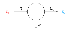 |


The dual combustion cycle (also known as the mixed cycle, Trinkler cycle, Seiliger cycle or Sabathe cycle) is a thermal cycle that is a combination of the Otto cycle and the Diesel cycle, first introduced by Russian-German engineer Gustav Trinkler, who never claimed to have developed the cycle himself.[1] Heat is added partly at constant volume (isochoric) and partly at constant pressure (isobaric),[2] the significance of which is that more time is available for the fuel to completely combust. Because of lagging characteristics of fuel this cycle is invariably used for Diesel and hot spot ignition engines. It consists of two adiabatic and two constant volume and one constant pressure processes.


The dual cycle consists of following operations:
- Process 1-2: Isentropic compression
- Process 2-3: Addition of heat at constant volume.
- Process 3-4: Addition of heat at constant pressure.
- Process 4-5: Isentropic expansion.
- Process 5-1: Rejection of heat at constant volume.
Bibliography
[edit]- Cornel Stan: Alternative Propulsion for Automobiles, Springer, 2016, ISBN 9783319319308, p. 48
References
[edit]- ^ Г. В. Тринклер: Двигателестроение за полустолетие. Очерки современника, 2nd edition, Речной транспорт, Saint Petersburg, 1958, p. 32
- ^ Lino Guzzella, Christopher Onder: Introduction to Modeling and Control of Internal Combustion Engine Systems, 2nd edition, Springer, Berlin/Heidelberg, ISBN 9783642107757, p. 334
This thermodynamics-related article is a stub. You can help Wikipedia by expanding it. |
Mixed/dual cycle
View on GrokipediaOverview
Definition and Characteristics
The mixed cycle, also known as the dual cycle or limited-pressure cycle, is a thermodynamic cycle that models the operation of internal combustion engines through a sequence of five idealized processes: isentropic compression of the working fluid, followed by partial heat addition at constant volume, partial heat addition at constant pressure, isentropic expansion, and finally constant-volume heat rejection.[3][4] This cycle assumes an ideal gas as the working fluid and reversible processes, providing a framework for analyzing engine performance under controlled conditions.[3] A key characteristic of the mixed cycle is its position as an intermediate model between the Otto cycle, which features heat addition entirely at constant volume (typical of spark-ignition gasoline engines), and the Diesel cycle, which involves heat addition entirely at constant pressure (characteristic of compression-ignition diesel engines).[4][3] It accounts for real-world engine behaviors such as ignition delay and phased combustion, where initial fuel ignition occurs rapidly at constant volume before transitioning to a slower-burning phase at constant pressure, offering a more accurate approximation of actual engine thermodynamics than the pure Otto or Diesel models.[4] The term "dual" arises from the dual modes of heat addition—constant volume and constant pressure—while "mixed" reflects its blending of spark-ignition and compression-ignition traits; it is particularly representative of the limited-pressure cycle in diesel engines, where combustion begins at constant volume due to the ignition delay before shifting to constant pressure as the piston moves.[3][4]Historical Development
The dual cycle was first introduced by Russian-German engineer Gustav Trinkler in the early 20th century.[6] The mixed or dual cycle concept developed in the early 20th century as a refinement to the ideal Otto and Diesel cycles, aiming to better represent the actual combustion processes observed in internal combustion engines where heat addition occurs partly at constant volume and partly at constant pressure.[7] This evolution addressed limitations in Rudolf Diesel's original cycle from the 1890s, which assumed constant-pressure heat addition but proved impractical due to high peak pressures (up to 90 bar) and challenges with coal dust fuel; by the late 1890s, Diesel's third prototype incorporated a mixed heat addition approach—initial rapid combustion at near-constant volume followed by controlled constant-pressure burning—while switching to more manageable petroleum-based fuels, reducing pressures to around 30 bar for reliable operation.[7] The cycle gained formal recognition in thermodynamic analysis during the 1920s and 1930s, often termed the Seiliger cycle after detailed studies of diesel combustion dynamics, providing a hybrid model that bridges the ideal efficiencies predicted by the Otto and Diesel cycles, with real engine thermal efficiencies typically ranging from 25-35% for gasoline (Otto-type) engines to 35-45% for diesel engines.[6] British engineer Harry Ricardo contributed significantly in the 1920s through experimental work on high-speed diesel engines, emphasizing the role of ignition delay—the brief period after fuel injection before rapid combustion—which the dual cycle's constant-volume phase effectively models, influencing its adoption in engine design literature.[8]Thermodynamic Processes
Isentropic Compression
In the mixed or dual cycle, the isentropic compression process, denoted as process 1-2, represents the initial stage where the air-fuel mixture undergoes reversible adiabatic compression from intake conditions at state 1 (characterized by low pressure and temperature) to a compressed state at state 2 (with significantly elevated pressure and temperature).[3][9] This process occurs as the piston moves from bottom dead center to top dead center, with the surroundings performing work on the gas, thereby increasing its internal energy without any heat transfer across the system boundaries.[9] As an idealization, it assumes no friction losses and maintains constant entropy, preparing the mixture for the subsequent dual-mode heat addition phases by achieving the necessary conditions for ignition.[3][10] The compression ratio, defined as , where and are the volumes at states 1 and 2, respectively, typically ranges from 14 to 22 in dual cycle operations, reflecting its diesel-like characteristics and enabling higher thermal efficiencies compared to spark-ignition cycles.[3] This ratio is higher than the 8 to 12 typical for Otto cycle engines, allowing for greater pressure and temperature rises during compression.[11] For an ideal gas approximation with air as the working fluid, the temperature and pressure at state 2 can be related to state 1 through the isentropic relations: where is the specific heat ratio, approximately 1.4 for air.[10][9] These equations underscore the process's role in amplifying thermodynamic potentials solely through mechanical compression.[3]Constant Volume Heat Addition
In the mixed or dual cycle, the constant volume heat addition process, denoted as process 2-3, occurs immediately following the isentropic compression of the working fluid, where heat is supplied at a fixed volume from the compressed state at point 2 to the intermediate state at point 3.[3] This phase simulates the initial combustion in spark-ignition engines or the early ignition in compression-ignition engines, such as diesel, where fuel oxidation begins rapidly without piston movement.[4] The process represents the ignition delay period in real engines, during which premixed fuel-air mixture combusts, leading to a sharp rise in pressure (P₃ > P₂) while the volume remains unchanged at the top dead center position.[12] This heat addition is modeled thermodynamically as an instantaneous input of energy from fuel combustion, resulting in a significant temperature increase (T₃ > T₂) within the closed system.[3] For an ideal gas working fluid, the relationship between states follows the ideal gas law at constant volume: The heat input during this process, Q_v, is given by: where C_v is the specific heat capacity at constant volume.[4] This formulation assumes constant specific heats and reversible conditions, capturing the rapid pressure buildup that transitions the cycle toward subsequent heat addition phases.[12]Constant Pressure Heat Addition
In the mixed or dual cycle, the constant pressure heat addition process, denoted as process 3-4, involves the addition of heat at constant pressure from state 3 to the peak state 4, approximating the latter stage of combustion in compression-ignition engines.[9] This phase follows the initial constant volume heat addition, where pressure has already risen significantly.[13] During this process, the volume expands from to as the piston moves away from top dead center, enabling controlled burning while maintaining fixed pressure.[9] The extent of heat addition is characterized by the cutoff ratio , which typically ranges from 1.2 to 2.5 depending on engine load and design.[13][3] This constant pressure phase models the diffusive combustion in diesel engines, simulating the slower mixing-controlled burning and flame development after the rapid initial premixed ignition, thereby avoiding the intense pressure spikes associated with purely constant volume combustion.[13][9] Assuming an ideal gas with constant specific heats, the temperature at state 4 relates to state 3 as follows: The heat input (per unit mass) is then: where is the specific heat at constant pressure.[13]Isentropic Expansion and Heat Rejection
In the mixed or dual cycle, the isentropic expansion process, denoted as 4-5, represents the power stroke where the high-pressure and high-temperature combustion products expand reversibly and adiabatically, performing work on the piston.[4] This process begins at state 4, immediately following the constant-pressure heat addition, and proceeds to state 5 at bottom dead center, with no heat transfer occurring during expansion to maintain reversibility.[3] The expansion ratio , where is the compression ratio and is the cutoff ratio, which is less than the compression ratio due to the volume increase during constant-pressure heat addition.[5] The work output for this process is given by the integral , which for an ideal gas equates to due to the adiabatic condition where the change in internal energy equals the work done.[3] The temperature at the end of expansion is determined by the isentropic relation for an ideal gas: or equivalently, where is the specific heat ratio.[4][5] This relation highlights the significant drop in temperature during expansion, converting thermal energy into mechanical work efficiently.[3] Following expansion, the constant-volume heat rejection process, 5-1, closes the cycle by expelling the combustion products at constant volume, returning the system to the initial intake state 1.[4] During this phase, heat is rejected to the surroundings, calculated as for a unit mass of ideal gas, where is the specific heat at constant volume.[3] This rejection occurs at the lowest temperature in the cycle (), minimizing thermodynamic losses by aligning with the second law's requirement for heat disposal at low temperatures.[4] The process simulates the exhaust stroke in actual engines, clearing the cylinder for the next cycle.[3]Analysis and Formulas
Pressure-Volume and Temperature-Entropy Diagrams
The pressure-volume (P-V) diagram of the dual cycle depicts a closed thermodynamic loop that combines elements of constant-volume and constant-pressure processes, providing a visual representation of the working fluid's state changes in an idealized internal combustion engine.[9] Process 1-2 illustrates isentropic compression as a steep curve, where volume decreases while pressure rises significantly due to adiabatic compression without heat transfer or entropy change. This is followed by constant-volume heat addition (2-3), shown as a vertical line upward, increasing pressure at fixed volume as heat is supplied rapidly, akin to ignition.[9] The subsequent constant-pressure heat addition (3-4) appears as a horizontal line to the right, where volume expands while pressure remains constant, representing continued combustion. This dual heat addition creates a distinctive "kink" at point 3 in the diagram, setting the dual cycle apart from the Otto cycle (which features only vertical heat addition) and the Diesel cycle (which lacks the vertical segment).[9] Isentropic expansion (4-5) traces a curve downward to the right, with volume increasing and pressure decreasing, followed by constant-volume heat rejection (5-1) as a vertical line downward to close the loop. The enclosed area within the P-V loop quantifies the net work output, calculated as the integral of P dV over the cycle, highlighting the balance between expansion work and compression work.[9] In real engines, deviations from ideal isentropic processes—such as friction and heat losses—introduce irreversibilities, manifesting as less steep curves in the compression and expansion segments, reducing the enclosed work area compared to the ideal case.[13] The temperature-entropy (T-S) diagram complements the P-V plot by emphasizing entropy changes and heat transfers, with the vertical axis for temperature and horizontal for entropy, aiding in the identification of reversible and irreversible behaviors. Processes 1-2 and 4-5 appear as vertical lines, indicating isentropic compression and expansion where entropy remains constant while temperature rises and falls, respectively, assuming no internal irreversibilities in the ideal model.[9] During heat addition (2-3-4), the path shifts rightward as entropy increases: the constant-volume segment (2-3) shows temperature rising with entropy gain proportional to the logarithm of the temperature ratio, followed by the constant-pressure segment (3-4) where entropy increases further due to volume expansion.[13] The area under the 2-3-4 curve, given by the integral of T dS, directly represents the total heat input Q_in, illustrating how combustion drives entropy production in the system. Constant-volume heat rejection (5-1) traces a path leftward with decreasing temperature and entropy, where the area under this segment quantifies heat output Q_out.[9] The enclosed T-S loop area equals the net work, per the first law, but in practice, irreversibilities during compression and expansion—such as throttling or mixing—cause additional entropy generation, shifting the paths rightward and reducing efficiency by increasing Q_out relative to Q_in.[13]Thermal Efficiency Derivation
The thermal efficiency of the dual cycle, denoted as η, is defined as the ratio of net work output to heat input, expressed as η = W_net / Q_in, where W_net = Q_in - Q_out and Q_out represents the heat rejected during the constant-volume process from state 5 to state 1.[14] This simplifies to η = 1 - Q_out / Q_in under the air-standard assumptions of an ideal gas with constant specific heats, reversible processes, and no heat losses.[14] To derive the explicit formula, consider the temperatures at each state, using the compression ratio r = V_1 / V_2, the pressure ratio ρ = P_3 / P_2 during constant-volume heat addition (process 2-3), and the cutoff ratio β = V_4 / V_3 during constant-pressure heat addition (process 3-4), with k = γ = c_p / c_v as the specific heat ratio. For the isentropic compression (1-2), T_2 = T_1 r^{k-1}. For constant-volume heat addition (2-3), T_3 = ρ T_2 = ρ T_1 r^{k-1}. For constant-pressure heat addition (3-4), T_4 = β T_3 = β ρ T_1 r^{k-1}. For the isentropic expansion (4-5), where V_5 = V_1, the volume ratio V_5 / V_4 = r / β, so T_5 = T_4 (V_4 / V_5)^{k-1} = T_4 (β / r)^{k-1} = ρ β^k T_1.[5] The heat input Q_in is the sum of constant-volume and constant-pressure contributions:Q_in = c_v (T_3 - T_2) + c_p (T_4 - T_3) = c_v T_1 r^{k-1} [ (ρ - 1) + k ρ (β - 1) ].
The heat rejected Q_out = c_v (T_5 - T_1) = c_v T_1 (ρ β^k - 1).
Thus, This expression shows that η depends on r, β, ρ, and k; increasing the compression ratio r raises η by enhancing the temperature rise during expansion relative to rejection, though practical limits arise from material stress and knocking constraints.[5][14] The theoretical thermal efficiency of the dual cycle typically ranges from 50% to 60%, depending on specific values of r (often 12-20), β (around 1.1-2), and ρ (1.1-2.5), positioning it between the higher efficiency of the Otto cycle (45-60% for similar r) and the lower efficiency of the Diesel cycle due to the combined heat addition modes allowing intermediate performance for the same compression ratio.[14][15]