
Community hub
0 subscribers8 pages, 0 posts
Recent from talks
All channels
Be the first to start a discussion here.
Be the first to start a discussion here.
Be the first to start a discussion here.
Be the first to start a discussion here.
Contribute something
Welcome to the community hub built to collect knowledge and have discussions related to Regenerative cooling.
Nothing was collected or created yet.
Regenerative cooling
View on Wikipediafrom Wikipedia
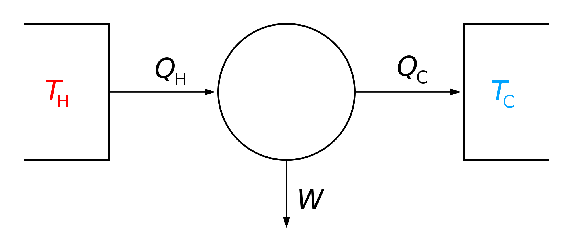
| Thermodynamics |
|---|
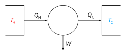 |


Regenerative cooling is a method of cooling gases in which compressed gas is cooled by allowing it to expand and thereby take heat from the surroundings. The cooled expanded gas then passes through a heat exchanger where it cools the incoming compressed gas.[1]
Regenerative cycles
[edit]History
[edit]In 1857, Siemens introduced the regenerative cooling concept with the Siemens cycle.[2] In 1895, William Hampson in England[3] and Carl von Linde in Germany[4] independently developed and patented the Hampson–Linde cycle to liquefy air using the Joule–Thomson expansion process and regenerative cooling.[5] On 10 May 1898, James Dewar used regenerative cooling to become the first to statically liquefy hydrogen.
See also
[edit]References
[edit]- ^ "Cryogenic microcooling Pag.25" (PDF). Archived from the original (PDF) on 2012-02-18. Retrieved 2008-11-06.
- ^ Charles William Siemens, "Improvements in refrigerating and producing ice, and in apparatus or machinery for that purpose", British patent no. 2064 (filed: July 29, 1857).
- ^ W. Hampson, "Improvements relating to the progressive refrigerating of gases", British patent 10,165 (filed: May 23, 1895).
- ^ Linde, Carl, "Verfahren zur Verflüssigung atmosphärischer Luft oder anderer Gase" (Method for the liquefication of atmospheric air or other gases), German patent 88,824 (filed: June 5, 1895).
- ^ Hydrogen through the Nineteenth Century
External links
[edit]- Regenerative Coolers Archived 2007-07-17 at the Wayback Machine
- Regenerative Cycle Video
Regenerative cooling
View on Grokipediafrom Grokipedia