

Community hub
Recent from talks
Contribute something
Nothing was collected or created yet.
Hot air engine
View on Wikipedia| Thermodynamics |
|---|
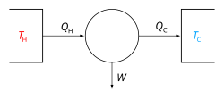 |


A hot air engine[1] (historically called an air engine or caloric engine[2]) is any heat engine that uses the expansion and contraction of air under the influence of a temperature change to convert thermal energy into mechanical work. These engines may be based on a number of thermodynamic cycles encompassing both open cycle devices such as those of Sir George Cayley[3] and John Ericsson[4] and the closed cycle engine of Robert Stirling.[5] Hot air engines are distinct from the better known internal combustion based engine and steam engine.
In a typical implementation, air is repeatedly heated and cooled in a cylinder and the resulting expansion and contraction are used to move a piston and produce useful mechanical work.
Definition
[edit].jpg)
The term "hot air engine" specifically excludes any engine performing a thermodynamic cycle in which the working fluid undergoes a phase transition, such as the Rankine cycle. Also excluded are conventional internal combustion engines, in which heat is added to the working fluid by combustion of fuel within the working cylinder. Continuous combustion types, such as George Brayton's Ready Motor and the related gas turbine, could be seen as borderline cases.
History
[edit]The expansive property of heated air was known to the ancients. Hero of Alexandria's Pneumatica describes devices that might be used to automatically open temple doors when a fire was lit on a sacrificial altar. Devices called hot air engines, or simply air engines, have been recorded from as early as 1699. In 1699, Guillaume Amontons (1663–1705) presented, to the Royal Academy of Sciences in Paris, a report on his invention: a wheel that was made to turn by heat.[6] The wheel was mounted vertically. Around the wheel's hub were water-filled chambers. Air-filled chambers on the wheel's rim were heated by a fire under one side of the wheel. The heated air expanded and, via tubes, forced water from one chamber to another, unbalancing the wheel and causing it to turn.
See:
- Amontons (20 June 1699) "Moyen de substituer commodement l'action du feu, à la force des hommes et des chevaux pour mouvoir les machines" (Means of conveniently substituting the action of fire for the force of men and horses in order to move [i.e., power] machines), Mémoires de l'Académie Royale des Sciences, pages 112-126. The Mémoires appear in the Histoire de l'Académie Royale des Sciences, année 1699, which was published in 1732. The operation of Amontons' moulin à feu (fire mill) is explained on pages 123-126; his machine is illustrated on the plate following page 126.
- For an account of Amontons' fire-powered wheel in English, see: Robert Stuart, Historical and Descriptive Anecdotes of Steam-engines and of Their Inventors and Improvers (London, England: Wightman and Cramp, 1829), vol. 1, pages 130-132; an illustration of the machine appears on [7] around the time when the laws of gasses were first set out, and early patents include those of Henry Wood, Vicar of High Ercall near Coalbrookdale Shropshire (English patent 739 of 1759) and Thomas Mead, an engineer from Sculcoats Yorkshire (English patent 979 of 1791),[8] the latter in particular containing the essential elements of a displacer type engine (Mead termed it the transferrer). It is unlikely that either of these patents resulted in an actual engine and the earliest workable example was probably the open cycle furnace gas engine of the English inventor Sir George Cayley c. 1807[9][10]
It is likely that Robert Stirling's air engine of 1818, which incorporated his innovative Economiser (patented in 1816) was the first air engine put to practical work.[11] The economiser, now known as the regenerator, stored heat from the hot portion of the engine as the air passed to the cold side, and released heat to the cooled air as it returned to the hot side. This innovation improved the efficiency of Stirling's engine and should be present in any air engine that is properly called a Stirling engine.
Stirling patented a second hot air engine, together with his brother James, in 1827. They inverted the design so that the hot ends of the displacers were underneath the machinery and they added a compressed air pump so the air within could be increased in pressure to around 20 atmospheres. It is stated by Chambers to have been unsuccessful, owing to mechanical defects and to “the unforeseen accumulation of heat, not fully extracted by the sieves or small passages in the cool part of the regenerator, of which the external surface was not sufficiently large to throw off the unrecovered heat when the engine was working with highly compressed air.”
Parkinson and Crossley, English patent, 1828 came up with their own hot air engine. In this engine the air-chamber is partly exposed, by submergence in cold water, to external cold, and its upper portion is heated by steam. An internal vessel moves up and down in this chamber, and in so doing displaces the air, alternately exposing it to the hot and cold influences of the cold water and the hot steam, changing its temperature and expansive condition. The fluctuations cause the reciprocation of a piston in a cylinder to whose ends the air-chamber is alternately connected.
In 1829 Arnott patented his air expansion machine where a fire is placed on a grate near the bottom of a close cylinder, and the cylinder is full of fresh air recently admitted. A loose piston is pulled upwards so that all the air in the cylinder above will be made to pass by a tube through the fire, and will receive an increased elasticity tending to the expansion or increase of volume, which the fire is capable of giving it.
He is followed the next year (1830) by Captain Ericsson who patented his second hot air engine. The specification describes it more particularly, as consisting of a “circular chamber, in which a cone is made to revolve on a shaft or axis by means of leaves or wings, alternately exposed to the pressure of steam; these wings or leaves being made to work through slits or openings of a circular plane, which revolves obliquely to, and is thereby kept in contact with the side of the cone.”
Ericsson built his third hot air engine (the caloric engine) in 1833 "which excited so much interest a few years ago in England; and which, if it should be brought into practical operation, will prove the most important mechanical invention ever conceived by the human mind, and one that will confer greater benefits on civilized life than any that has ever preceded it. For the object of it is the production of mechanical power by the agency of heat, at an expenditure of fuel so exceedingly small, that man will have an almost unlimited mechanical force at his command, in regions where fuel may now be said hardly to exist".
1838 sees the patent of Franchot hot air engine, certainly the hot air engine that was best following the Carnot requirements.
So far all these air engines have been unsuccessful, but the technology was maturing. In 1842, James Stirling, the brother of Robert, build the famous Dundee Stirling Engine. This one at least lasted 2–3 years but then was discontinued due to improper technical contrivances. Hot air engines is a story of trials and errors, and it took another 20 years before hot air engines could be used on an industrial scale. The first reliable hot air engines were built by Shaw, Roper, Ericsson. Several thousands of them were built.
Commercial Manufacturers
[edit]Hot engines found a market for pumping water (mainly to a household water tank) as the water inlet provided the cold required to maintain the temperature difference, though they did find other commercial uses.
- Hayward, Tyler & Co of London. Engines for pumping water and working Punkahs c1876-1883.[12]
- Hayward-Tyler & Co of London. Domestic water supply (Rider's patent) c1888-1901.[13]
- W.H. Bailey & Co, Salford. Engines for pumping domestic water and operating stable machinery c1885-1887[14]
- Adam Woodward & Sons, Ancoats, Manchester. Robinson's patent. c1887[15]
- Norris & Henty, London. Resellers of 'Robinson' type pumping engines. c1898-1901[16]
- C.H. Delamater & Co, Delamater Iron Works, New York. 'Rider' and 'Ericsson' type engine. 1870s-1898
- Rider Engine Company, Walden, New York. 1879-1898
- Rider-Ericsson Engine Company, Walden, New York. 1898-
Thermodynamic cycles
[edit]A hot air engine thermodynamic cycle can (ideally) be made out of 3 or more processes (typically 4). The processes can be any of these:
- isothermal process (at constant temperature, maintained with heat added or removed from a heat source or sink)
- isobaric process (at constant pressure)
- isometric / isochoric process (at constant volume)
- adiabatic process (no heat is added or removed from the working fluid)
- isentropic process, reversible adiabatic process (no heat is added or removed from the working fluid - and the entropy is constant)
- isenthalpic process (the enthalpy is constant)
Some examples (not all hot air cycles, as defined above) are as follows:
| Cycle | Compression, 1→2 | Heat addition, 2→3 | Expansion, 3→4 | Heat rejection, 4→1 | Notes |
|---|---|---|---|---|---|
| Power cycles normally with external combustion - or heat pump cycles: | |||||
| Bell Coleman | adiabatic | isobaric | adiabatic | isobaric | A reversed Brayton cycle |
| Carnot | isentropic | isothermal | isentropic | isothermal | Carnot heat engine |
| Ericsson | isothermal | isobaric | isothermal | isobaric | The second Ericsson cycle from 1853 |
| Rankine | adiabatic | isobaric | adiabatic | isobaric | Steam engines |
| Hygroscopic | adiabatic | isobaric | adiabatic | isobaric | |
| Scuderi | adiabatic | variable pressure and volume |
adiabatic | isochoric | |
| Stirling | isothermal | isochoric | isothermal | isochoric | Stirling engines |
| Manson | isothermal | isochoric | isothermal | isochoric then adiabatic | Manson and Manson-Guise engines |
| Stoddard | adiabatic | isobaric | adiabatic | isobaric | |
| Power cycles normally with internal combustion: | |||||
| Atkinson | isentropic | isochoric | isentropic | isochoric | Differs from Otto cycle in that V1 < V4. |
| Brayton | adiabatic | isobaric | adiabatic | isobaric | Ramjets, turbojets, -props, and -shafts. Originally developed for use in reciprocating engines. The external combustion version of this cycle is known as the first Ericsson cycle from 1833. |
| Diesel | adiabatic | isobaric | adiabatic | isochoric | Diesel engine |
| Humphrey | isentropic | isochoric | isentropic | isobaric | Shcramjets, pulse- and continuous detonation engines |
| Lenoir | isochoric | adiabatic | isobaric | Pulse jets. 1→2 accomplishes both the heat rejection and the compression. Originally developed for use in reciprocating engines. | |
| Otto | isentropic | isochoric | isentropic | isochoric | Gasoline / petrol engines |
Yet another example is the Vuilleumier cycle. [17]
See also
[edit]References
[edit]- ^ "An Inquiry into the Hot Air Engines of the 19th Century". hotairengines.org.
- ^ Robert Sier (1999). Hot air caloric and stirling engines. Vol.1, A history (1st Edition (Revised) ed.). L.A. Mair. ISBN 0-9526417-0-4.
- ^ "Cayley's life and Air Engines". hotairengines.org.
- ^ "Ericsson's life and Air Engines". hotairengines.org.
- ^ "Stirling's life and Air Engines". hotairengines.org.
- ^ "Amontons' Fire Wheel". hotairengines.org.
- ^ page 351.
- ^ Robert Sier (1999). Hot air caloric and stirling engines. Vol.1, A history, page 56 (1st Edition (Revised) ed.). L.A. Mair. ISBN 0-9526417-0-4.
- ^ "Stirling engine history". Archived from the original on 2009-09-20. Retrieved 2007-07-09.
- ^ Detailed contents of the book Hot air caloric and stirling engines. Vol.1, A history
- ^ Finkelstein, T; Organ, A.J (2001). Chapter 2.2 Air Engines. Professional Engineering Publishing. ISBN 1-86058-338-5.
- ^ "Advert". Friend of India and Statesman. 30 November 1877. p. 4.
- ^ "Advert". Field. 14 March 1896. p. 64.
- ^ "Advert". Field. 10 July 1886. p. 64.
- ^ "Advert". Widnes Examiner. 3 December 1887. p. 4.
- ^ "Advert". Field. 26 January 1901. p. 59.
- ^ Wurm, Jaroslav (1991). Stirling and Vuilleumier heat pumps: design and applications. McGraw-Hill. ISBN 0-07-053567-1.
External links
[edit]- Introduction to Stirling-Cycle Machines
- Pioneers in Air Engine Designs (Select the desired biography)
- Apparatus for the Method of Heat Differentiation Vuilleumier patent
- Inquiry into the Hot Air Engines of the 19th Century
Hot air engine
View on GrokipediaOverview
Definition and Basic Operation
A hot air engine, also known as a caloric engine, is a heat engine that converts thermal energy into mechanical work by exploiting the expansion and contraction of air or another gas as the working fluid, driven by cyclic heating and cooling.[1] These engines operate on external combustion principles, where heat is supplied from an outside source rather than generated internally through fuel burning.[5] Unlike internal combustion engines, which ignite fuel directly within the cylinder to produce expanding gases, hot air engines maintain a sealed working fluid separated from the combustion process.[5] In contrast to steam engines, hot air engines use a gaseous working fluid without phase changes, relying solely on thermal expansion and contraction of the gas. The basic components of a hot air engine include a heat source, such as a flame or solar collector, to provide external heating; a cold sink, typically ambient air or water, for cooling; one or more pistons to manage gas compression and expansion; and cylinders to enclose the working gas. The most prominent example, the Stirling engine, additionally incorporates a displacer piston that shuttles the working gas between hot and cold zones without performing net work and a regenerator, a porous matrix that stores heat during cooling and releases it during heating to improve efficiency.[1][6] The system maintains a closed-cycle nature, ensuring the working gas—often air, helium, or hydrogen—circulates repeatedly without loss.[1] In operation, the engine follows a thermodynamic cycle involving heat addition to expand the gas, expansion to produce work, heat rejection to contract the gas, and compression to return to the initial state. In regenerative designs like the Stirling engine, heat addition occurs as the gas is exposed to the hot source, causing it to expand and increase pressure; a displacer then shifts the gas while the power piston moves during the expansion phase, converting the pressure rise into mechanical output.[1][6] Heat rejection follows as the gas is transferred to the cold sink, where it cools and contracts, passing through the regenerator to store excess heat.[1] Finally, the compression phase returns the gas to the starting position via the power piston's return stroke, completing the cycle.[1] Simpler hot air engines may omit the displacer and regenerator, using direct piston motion to cycle the gas through heating and cooling zones.Advantages and Disadvantages
Hot air engines offer several practical advantages stemming from their external combustion design, which separates the heat source from the working fluid. They operate silently, without the explosive noise or vibrations associated with internal combustion engines, making them suitable for noise-sensitive applications. This quiet performance arises from the continuous, external heating process that avoids rapid pressure changes within the cylinders. Additionally, their safety profile is enhanced by the absence of high-pressure boilers and the use of sealed working fluids, significantly reducing risks of explosion or scalding compared to steam engines. Fuel flexibility is another key benefit, as these engines can utilize diverse heat sources, including waste heat, solar energy, biofuels, or conventional fuels, without requiring modifications to the core mechanism. Low maintenance requirements further contribute to their appeal, with fewer moving parts and no valves or ignition systems, leading to reduced wear and longer operational life. Environmentally, hot air engines produce no direct emissions from the combustion chamber since heating occurs externally, allowing for cleaner operation when paired with low-emission heat sources like solar or biomass. Studies indicate potential for lower NOx emissions compared to internal combustion engines. Despite these strengths, hot air engines face notable disadvantages that limit their widespread adoption. Their power-to-weight ratio is generally lower than that of internal combustion engines; historical low-pressure designs achieved specific powers around 0.04 kW/kg, while modern high-pressure variants reach up to 0.3 kW/kg due to the bulky design necessitated by large gas volumes and heat exchangers.[7] This results in higher overall size and weight, rendering them less practical for mobile applications like transportation. Thermal inertia from the external heating process also causes slower response times to load changes, with warm-up periods that can reduce efficiency during transient operations. Material challenges pose additional hurdles, as operating temperatures on the hot side often reach 300–1000°C, inducing thermal stress and complicating sealing in high-pressure variants (up to 220 bar), which demand robust materials like stainless steel. Historically, these factors have driven higher initial costs due to the precision manufacturing required for heat exchangers and regenerators. Modern advancements, such as the use of ceramics like silicon nitride (Si₃N₄) and silicon carbide (SiC) in critical components, help mitigate thermal stress and improve high-temperature durability, enabling operation above 1200°C with enhanced erosion resistance and reduced degradation.Historical Development
Early Inventions
The origins of hot air engines trace back to the late 17th century, when inventors began exploring the potential of heated air expansion as a source of motive power, marking the shift from purely mechanical or steam-based devices to thermal air engines. In 1699, French physicist Guillaume Amontons proposed the first such concept with his "atmospheric fire-mill," an open-cycle apparatus designed to harness the buoyancy of heated air. The device featured a vertical wheel with radial vanes partially immersed in water; air in one set of vanes was heated in a furnace, causing it to expand and rise, displacing water and creating an imbalance that rotated the wheel to drive a mill. This demonstration model generated only minimal power, sufficient for illustrative purposes but not practical application, relying on continuous air intake and exhaust through a chimney effect.[8][9] Early 18th-century efforts built on this foundation but remained largely theoretical and experimental. Around the same period, French inventor Jean de Hautefeuille advanced related ideas from 1678 to 1703, proposing air pumps heated by controlled gunpowder combustion to exploit thermal expansion for raising water, though his schemes involved intermittent explosions and lacked refined containment. These conceptual prototypes underscored the era's recognition of air's expandability under heat but were hindered by rudimentary materials and imprecise control, rendering them impractical for sustained operation.[10][11] By the late 18th century, inventors sought to address the inefficiencies of open-cycle designs, which wasted heat by exhausting expanded air, paving the way for concepts that aimed to contain the working fluid. In 1791, English engineer John Barber patented a pioneering system—a precursor to the gas turbine—that compressed air, heated it externally with fuel combustion, and expanded it through turbine blades to produce rotary motion in a continuous flow, though it exhausted to the atmosphere. Although no working prototype was constructed due to metallurgical and sealing challenges, Barber's design emphasized the efficiency gains of compressing and heating air, influencing later developments. These early inventions shared critical limitations that curtailed their viability: low thermal efficiency from the absence of regenerative heat recovery, inadequate seals allowing air leakage, and intermittent heating cycles that caused thermal stress and rapid component wear, often resulting in operational lifespans measured in hours rather than days. Such constraints, rooted in the era's limited understanding of thermodynamics and materials science, confined hot air engines to laboratory curiosities until subsequent refinements.[2]Key Developments in the 19th and 20th Centuries
In 1816, Scottish clergyman Robert Stirling patented the first practical closed-cycle hot air engine, featuring a novel regenerator that captured and reused waste heat to improve efficiency, marking a significant advancement over earlier open-cycle designs.[12] This engine was constructed in collaboration with his brother James Stirling, an engineer, who later refined the design in the 1820s by incorporating displacer mechanisms for better gas management.[12] The first commercial application came in 1818, when a Stirling engine was installed to pump water from a quarry in Scotland, demonstrating its reliability for small-scale industrial tasks.[12] During the mid-19th century, James Stirling further evolved the engine in the 1840s, enabling larger and more efficient installations.[1] Concurrently, Swedish-American inventor John Ericsson advanced hot air engine technology through his "caloric engines," beginning with a 1833 marine prototype intended to rival steam engines but ultimately failing due to excessive weight and insufficient power density for shipboard applications.[13] Ericsson improved upon this in the 1850s by integrating an advanced regenerator, which boosted thermal efficiency and enabled larger-scale prototypes capable of generating several horsepower.[14] By the 1890s, Ericsson's designs reached mass production, with companies manufacturing units for stationary power in workshops and farms, reflecting adoption of hot air engines during the 1880s and early 1900s for low-power needs like grinding and pumping.[15] The early 20th century saw a sharp decline in hot air engine use, primarily due to the rise of affordable electric motors that offered simpler operation, higher power density, and no requirement for continuous heat sources, rendering Stirling and Ericsson types obsolete for most terrestrial applications by the 1920s.[7] Interest revived in the 1930s through work at Philips Research Laboratories, which developed practical engines leading to applications in cryocoolers and other devices. However, further revival came in the mid-20th century with the invention of the free-piston Stirling engine in 1964 by William T. Beale at Ohio University, which eliminated crankshaft linkages for reduced friction and maintenance, tying back to historical closed-cycle principles while enabling compact designs.[16] This innovation drew NASA's attention in the 1960s and 1970s for space applications, where Stirling converters were developed for reliable, long-life power generation in radioisotope systems, leading to prototypes tested for missions requiring high efficiency in vacuum environments.[17]Thermodynamic Principles
Core Cycles
The Stirling cycle is a closed thermodynamic cycle that forms the basis for many hot air engines, comprising two isothermal processes for heat addition and rejection and two isochoric processes for internal heat transfer.[18] In the ideal form, it begins with isothermal compression of the working gas at the cold reservoir temperature , where heat is rejected to the surroundings; this is followed by isochoric heat addition from the regenerator, raising the temperature to the hot reservoir temperature at constant volume. The cycle then proceeds to isothermal expansion at , absorbing heat from the hot source and producing work, before concluding with isochoric heat rejection to the regenerator, returning the gas to .[19] Regeneration is central to the cycle's performance, as a thermal storage matrix captures heat during the isochoric cooling and releases it during the subsequent heating, thereby approaching reversible operation and minimizing external heat requirements.[19] With perfect regeneration, the Stirling cycle achieves the Carnot efficiency, given by where and are the absolute temperatures of the hot and cold reservoirs, respectively.[19] The net work output per cycle equals , with representing the heat input during isothermal expansion.[19] On a pressure-volume (PV) diagram, the cycle appears as a closed loop with curved lines for the isothermal processes (following PV = constant during volume change) and vertical lines for the isochoric processes (constant volume during pressure change), highlighting the enclosed area as net work.[18] The temperature-entropy (TS) diagram depicts the isothermal processes as horizontal lines at and (constant temperature with entropy variation due to heat transfer), connected by sloped lines for the isochoric regenerations (entropy change with temperature via , where is the specific heat at constant volume).[18] The Ericsson cycle, another foundational cycle for hot air engines, similarly features two isothermal and two constant-pressure (isobaric) processes, but substitutes isobaric regeneration for the isochoric type in the Stirling design.[20] It operates through isothermal compression at (heat rejection), isobaric heat addition from the regenerator and external source to reach , isothermal expansion at (heat absorption and work output), and isobaric heat rejection to the regenerator.[19] Like the Stirling, regeneration transfers heat internally during the isobaric phases via a counterflow heat exchanger, though historical implementations often operated as open cycles (drawing atmospheric air) or closed variants with imperfect regeneration, leading to lower practical efficiencies.[19] The ideal efficiency is also the Carnot limit , with net work .[20] The PV diagram for the Ericsson cycle shows horizontal lines for the isobaric processes (constant pressure with volume change) and curved isothermal lines (following ), forming a loop where the isobaric segments emphasize continuous heat transfer surfaces.[20] In the TS diagram, the isothermal processes are horizontal at and , linked by sloped isobaric lines (entropy change via , where is the specific heat at constant pressure), underscoring the role of extended heat exchange in regeneration.[20] Compared to the Stirling cycle, the Ericsson's isobaric regeneration supports higher operating pressures and potentially greater mean effective pressure but demands larger heat exchanger volumes to achieve effective constant-pressure heat transfer, making it less compact for piston-based hot air engines.[19] The Stirling's isochoric approach enables more integrated regenerators within the cylinder, favoring compactness, though both cycles rely on regeneration to mitigate irreversibilities and approach theoretical Carnot performance in idealized conditions.[19]Efficiency and Performance Factors
Hot air engines, such as Stirling engines, exhibit practical efficiencies limited by various losses that reduce performance below ideal thermodynamic predictions. Thermal losses primarily stem from conduction through cylinder walls and incomplete heat recovery in the regenerator, where effectiveness typically ranges from 70% to 90%, leading to incomplete recycling of heat during the cycle. Mechanical losses occur due to friction in pistons, seals, and bearings, consuming approximately 5-10% of the generated work, while pressure drops in heat exchangers and the regenerator further diminish output by increasing fluid resistance and reducing cyclic work. These factors collectively account for significant deviations from ideal operation, with regenerator imperfections alone capable of halving theoretical efficiency in some designs.[21][22][23] Performance metrics for hot air engines reflect these limitations, with typical thermal efficiencies ranging from 20% to 40%, in contrast to ideal Carnot efficiencies of 50-70% for temperature ranges commonly used (e.g., cold side at 300 K and hot side up to 1000 K). Power output scales linearly with mean operating pressure, often 1-10 bar, and temperature difference (ΔT) up to 700°C, enabling outputs from a few watts in small prototypes to several kilowatts in larger units; specific power densities achieve 50-200 W/kg in optimized configurations. For instance, increasing mean pressure from 2.76 MPa to 5.52 MPa can boost power from about 3.5 kW to over 7.5 kW at fixed speeds, while higher ΔT enhances cycle work but is constrained by material limits.[24][25] Optimization strategies focus on mitigating these losses to approach theoretical limits. Regenerator design employs porous metals or ceramics to maximize surface area and heat transfer, improving effectiveness and reducing reheat losses. Selecting helium or hydrogen as the working gas, rather than air, leverages their superior thermal conductivity to accelerate heat exchange and increase cycle speed by 2-3 times, though hydrogen's lower viscosity further enhances performance at the cost of safety considerations. Mean pressure directly influences power, as higher values amplify cyclic work proportional to pressure, but must balance against increased mechanical stress. The real efficiency can be approximated as where , is regenerator effectiveness, and aggregates fractional losses; for a ΔT of 600°C (e.g., K, K), this yields with and typical losses around 20%.[21][27][1][22] Scaling challenges further impact performance, particularly at small sizes where elevated surface-to-volume ratios amplify relative heat losses through conduction and radiation, dropping efficiencies below 20% in micro-scale engines. High-speed operation is constrained by gas dynamics, including viscous effects and pressure wave propagation, limiting rotational rates and power density in compact designs. These issues underscore the need for advanced materials and microfabrication to maintain viability in miniaturized applications.[28][29]Engine Designs and Types
Stirling Engines
Stirling engines represent the most prominent and widely studied type of hot air engine, optimized for the Stirling cycle involving isothermal compression and expansion with isochoric heat addition and rejection.[30] These engines operate by cyclically heating and cooling a fixed mass of working gas, typically air, helium, or hydrogen, within a closed system to drive mechanical work through piston motion.[31] The design incorporates an integral regenerator, often constructed from a fine stainless steel mesh or metallic wire matrix, which stores and transfers heat between the hot and cold phases of the cycle, significantly enhancing thermal efficiency by recovering otherwise wasted energy.[31] Key mechanical features include drive mechanisms such as the rhombic drive, which uses synchronized gears and rods to achieve dynamic balance and minimize vibration in single-cylinder setups,[32] and double-acting configurations where both sides of the piston are alternately exposed to hot and cold working fluid, enabling continuous power output without intermittent strokes.[33] Stirling engines are classified into several configurations based on piston and displacer arrangements. The alpha configuration employs two power pistons in separate cylinders—one hot and one cold—connected via a regenerator, allowing direct gas transfer between temperature zones for high specific power, often using drives like the Ross yoke or multi-cylinder swashplate setups.[30][31] In contrast, the beta configuration integrates a displacer and power piston within a single cylinder, where the displacer shuttles gas between hot and cold ends without producing net work, while the power piston extracts mechanical output.[30][31] The gamma configuration separates the displacer into its own cylinder from the power piston, simplifying construction and aiding experimental studies, though it may exhibit slightly lower efficiency due to increased dead volume.[30][31] A specialized free-piston variant eliminates a mechanical linkage to the crankshaft, instead coupling the oscillating piston directly to a linear alternator for electrical generation, relying on gas springs for return motion and offering reduced wear and precise control.[34] Operationally, Stirling engines maintain a phase angle of approximately 90 degrees between the displacer and power piston motions to optimize work extraction, ensuring the gas is displaced to the hot side during expansion and to the cold side during compression.[35] Startup typically requires an external impulse, such as spinning a flywheel to overcome initial friction and build momentum until thermal gradients establish self-sustaining oscillation.[36] Historical examples include Robert Stirling's original 1816 patent design, a low-speed, air-cooled engine with a single displacer and piston operating at atmospheric pressure, producing about 2 horsepower for quarry pumping applications.[37] A notable 20th-century advancement is NASA's MOD II engine, a V-4 alpha-type configuration developed for automotive use in the 1980s, achieving 60 kW power output and 38.5% thermal efficiency at 1200 rpm using hydrogen as the working gas.[38] These designs offer advantages in compactness relative to power output, with modular components enabling integration into space-constrained systems, and scalability from small demonstration toys generating milliwatts to kilowatt-scale units for practical use.[39][29]Ericsson and Other Variants
The Ericsson engine, developed by Swedish-American inventor John Ericsson in the mid-19th century, represented an early attempt to realize the Ericsson cycle through isobaric heating and cooling processes, where air is heated and expanded at constant pressure to drive mechanical work. Unlike piston-dominated designs, Ericsson's configurations often incorporated bellows or diaphragms to facilitate air compression and transfer, minimizing friction and enabling continuous flow in open-cycle operation at near-atmospheric pressure. This approach allowed for external heating via furnaces, with heated air circulating through wire-gauze regenerators to recover thermal energy before cooling and exhaust.[13][40] A notable application was the 1851 caloric ship Ericsson, a 260-foot paddle steamer powered by four massive single-acting vertical cylinders, each with a 14-foot bore and 6-foot stroke, mounted over coal-fired furnaces. Ericsson claimed the engines could deliver up to 2,400 horsepower, enabling speeds of 10 miles per hour on reduced coal consumption compared to steamships, but in practice, it achieved 7-8 miles per hour due to the ship's excessive weight, low freeboard, and stability issues. The ship's engine ran flawlessly for 73 hours during trials but proved too heavy and complex for maritime use, and the vessel sank in a storm off New York Harbor in 1854.[40][41][42] Other variants emerged in the late 19th century, adapting hot air principles to address specific limitations. Similarly, the Rider engine, developed in the 1880s by the Rider-Ericsson Engine Company, featured opposed pistons within a single cylinder—one for compression and one for power—integrated with water cooling jackets around the warm cylinder to maintain seals and prevent thermal damage during prolonged operation. These designs prioritized reliability for pumping applications, with the Rider model using the pumped water itself for cooling, enabling widespread use in rural water supply systems.[40][43] Unique mechanical features distinguished these variants from more conventional closed-cycle engines. Open-cycle Ericsson configurations emphasized continuous atmospheric air flow, avoiding the need for sealed systems but requiring robust regenerators for efficiency. Rotary designs, such as early 1900s vane-type engines, simplified motion by replacing reciprocating pistons with rotating vanes to reduce mechanical complexity and vibration, though they saw limited adoption due to sealing difficulties. Hybrid caloric engines, like some Ericsson-Rider combinations, integrated hot air expansion with steam elements for auxiliary power, blending caloric and vapor cycles to improve starting reliability in variable conditions.[13][40] In the 20th century, low-temperature difference (LTD) engines revived interest in hot air variants for niche applications. Pioneered by Croatian engineer Ivo Kolin in the 1970s, these engines operate with temperature differentials under 100°C, often using simple displacer mechanisms and ambient heat sources like solar collectors or hand warmers to drive slow oscillations, prioritizing educational demonstration and toy models over high power output. Modern Ericsson-style engines remain rare due to inherent complexities in isobaric sealing, which led to air leakage and low adoption historically, while LTD variants continue in low-stakes roles like solar-powered gadgets.[44][13]Manufacturers and Production
Historical Manufacturers
The Stirling brothers, Robert and James, established early production of hot air engines at the Dundee Foundry in Scotland during the 1818–1840s period, focusing primarily on beta-type designs for industrial applications such as mining pumps. Their most notable output included a large 1843 engine with a 16-inch piston and 48-inch stroke, capable of delivering approximately 35 horsepower to power the foundry's machinery for two years until mechanical failure occurred due to material limitations. Overall, production was limited, emphasizing reliability over scale, with engines typically under 5 horsepower for pumping tasks in quarries and breweries.[45][46][47] In the United States, the Ericsson Manufacturing Company, based in New York, advanced hot air engine production from the 1850s through the 1920s, drawing on John Ericsson's caloric engine patents to create versatile models for agricultural and factory use. Building on Ericsson's 19th-century innovations like the regenerator and air-compression systems, the firm produced units ranging from 0.5 to 100 horsepower, including the 1895 "Caloric" model featuring air-cooling for improved efficiency in water-pumping applications. These engines were marketed for their safety and low operating costs compared to steam alternatives, finding widespread adoption on farms and in small factories.[47][43] Other notable firms included the Rider-Ericsson Engine Company in Walden, New York, which from the 1890s specialized in oscillating-piston designs based on Ericsson's and A.K. Rider's patents, producing 30,000 to 40,000 pumping engines that became the world's largest output of hot air types.[43] In the UK, companies like W.H. Bailey & Co. in Salford manufactured compact models in the 1880s, such as 0.5-horsepower units for domestic water lifting.[48][47] European makers, including Bolckow Vaughan in Middlesbrough, integrated hot air engines into ironworks operations during the late 19th century for auxiliary pumping, leveraging waste heat for efficiency. Innovations across these firms, such as multi-cylinder configurations, enabled higher power outputs up to 100 horsepower in select models.[47] Global production of hot air engines peaked at tens of thousands of units by the early 20th century, predominantly small-scale models under 10 horsepower suited for low-demand tasks like water pumping and ventilation. However, output declined sharply after 1910 due to the rise of electrification for powering machinery and the advent of cheaper, higher-performance internal combustion engines, which offered greater portability and fuel economy.[49][43]Modern Producers and Innovations
In the 21st century, several companies have emerged as key producers of hot air engines, primarily focusing on Stirling variants for specialized applications. Qnergy, with operations in Israel and the United States, specializes in linear free-piston Stirling engines designed for remote power generation in the oil and gas sector, delivering outputs from 1 to 10 kW while converting waste methane into electricity with minimal maintenance.[50] Sunpower Inc., based in the United States, develops free-displacer and free-piston Stirling technologies for cryocoolers and linear alternators, emphasizing high reliability in niche environments like space and medical cooling.[51] Collaborations between NASA and the U.S. Department of Energy (DoE) in the 2000s involved Infinia Corporation (now part of Qnergy) in prototyping Stirling convertors, including efforts toward automotive applications that aimed to leverage high efficiency for hybrid vehicles, though these did not reach mass production.[52] Recent innovations in hot air engine design have centered on enhancing performance through advanced materials and optimized operating parameters. The use of ceramics in engine components enables operation at temperatures up to 800°C, improving thermal stability and efficiency in high-heat environments like solar concentrators.[53] Charging engines with helium at pressures ranging from 20 to 150 bar has doubled power density compared to air-filled systems, allowing compact designs for portable applications.[54] Additionally, micro-Stirling engines fabricated using micro-electro-mechanical systems (MEMS) provide cooling capacities under 1 W, suitable for electronics and biomedical devices, with prototypes demonstrating feasibility through silicon and ceramic microstructures.[55] Global production of hot air engines remains a niche market, valued at approximately $918 million as of 2024.[56] This limited scale reflects the technology's focus on high-value, low-volume applications, exemplified by Sunpower's free-displacer designs used in ultra-low temperature freezers that require virtually no maintenance.[57] Contemporary trends include integrating Stirling engines with renewable sources, such as 2020s solar-Stirling hybrid systems that achieve up to 25% solar-to-electric efficiency in dish concentrator setups.[58] Cost reductions have been pursued through 3D printing of complex regenerators, enabling intricate geometries that boost heat transfer while lowering fabrication expenses.[59] In 2025, NASA continued advancing Stirling technology with the development of replicable simulator hardware to support rapid controller and power electronics testing for space applications.[3] However, challenges persist in scaling for mass markets, with production costs around $5,000 per kW hindering broader adoption due to competition from cheaper alternatives like internal combustion engines.[60]Applications
Traditional Uses
Hot air engines, particularly Stirling designs, found early application in industrial pumping during the 19th century. In Scottish coal mines and quarries from the 1820s to 1850s, these engines were employed to drain water, offering a safer alternative to steam engines in explosive environments. The external combustion process eliminated the risk of boiler explosions and produced no sparks, making them reliable for hazardous underground operations where firedamp posed a constant threat.[61][62] In agricultural and small-scale power settings, Ericsson-model hot air engines powered equipment in the United States and Europe from the 1880s to 1910s, especially in remote rural areas lacking electrical infrastructure. These engines, typically rated at 1 to 5 horsepower, drove grain mills, saws for lumber processing, and irrigation pumps, providing consistent low-maintenance operation fueled by simple heat sources like wood or coal. Their portability and ability to run on low-grade fuels suited isolated farms, enabling mechanized tasks without the need for complex steam systems.[63][15] Attempts to apply hot air engines to marine propulsion, such as John Ericsson's early caloric ship experiments in the 1850s, ultimately failed due to insufficient power output and excessive space requirements compared to steam alternatives. However, land-based stationary uses proved more successful, with these engines generating power for lighthouses where quiet operation was essential. In lighthouses, Ericsson hot air engines drove fog signal compressors starting in the 1860s, valued for their low noise and steady performance in remote coastal installations.[64][65] Small-scale "caloric" hot air engines also entered household use during the Victorian era, extending into the early 1900s, for light domestic tasks. These compact units, often under 1 horsepower, operated sewing machines in homes without access to larger power sources, leveraging minimal heat input for precise mechanical drive. Additionally, they powered fans for air circulation, heated by lamps or small burners, providing a non-electric cooling solution in an era before widespread electrification.[66][61] Hot air engines reached their peak adoption around 1890 to 1910, produced in the thousands for pumping, small machinery, and stationary power. This period of growth was driven by improvements in manufacturing, but the rise of reliable electric motors and internal combustion engines rapidly displaced them by the 1920s, favoring higher efficiency and easier maintenance in most applications.[49]Modern and Emerging Applications
In contemporary applications, Stirling cycle cryocoolers play a vital role in achieving ultra-low temperatures for scientific and industrial purposes. These devices leverage the reverse Stirling cycle to provide reliable cooling in space missions, such as the Reuven Ramaty High Energy Solar Spectroscopic Imager (RHESSI), where a Sunpower 80 K Stirling cooler maintains infrared detectors at approximately 80 K for extended operations.[67] In medical imaging, Stirling cryocoolers cool superconducting magnets in MRI systems to around 4 K, eliminating the need for liquid helium and enabling more compact, cost-effective designs that support high-field imaging up to 7 T.[68] For liquefied natural gas (LNG) production, Stirling cryocoolers achieve relative Carnot efficiencies exceeding 20% at cryogenic temperatures below 100 K, facilitating efficient reliquefaction of boil-off gases in small-scale plants with capacities up to 27 L/h of LNG.[69] Stirling engines have found significant integration in renewable energy systems, enhancing efficiency in solar and biomass applications. Concentrated solar power setups using dish-Stirling systems, such as 25 kW prototypes deployed in desert environments, convert sunlight to electricity at peak efficiencies of up to 31.6%, with average net efficiencies around 22.8% under real-world conditions.[70] In biomass combined heat and power (CHP) units for residential and small-scale applications, Stirling engines recover up to 80% of waste heat for domestic heating, yielding total CHP efficiencies of 79-80% while generating 1-10 kW of electricity from wood pellets or agricultural residues.[71] Although large-scale automotive adoption of Stirling engines faltered due to high costs and complexity, prototypes from the 1970s and 1980s, including NASA/DOE developments like the Automotive Stirling Engine (ASE), demonstrated multifuel capabilities and efficiencies up to 40% but failed to compete commercially with internal combustion engines.[7] Niche portable uses persist in hybrid range extenders, exemplified by Dean Kamen's 2010s designs for Segway-like generators and electric vehicles, where compact Stirling units produce 3-10 kW from diverse fuels to recharge batteries quietly and with low emissions.[72] Military applications include developmental Stirling engines for long-endurance drones, offering silent, fuel-flexible power for reconnaissance missions, though power-to-weight challenges limit widespread deployment.[73] Emerging applications emphasize sustainability and decentralization, with helium-charged micro-CHP Stirling systems (1-5 kW) enabling off-grid home power and heating from natural gas or biomass, achieving electrical efficiencies of 25-35% and total CHP efficiencies over 80%.[74] Wastewater heat recovery prototypes utilize low-grade thermal energy (around 40-60°C) from sewage to drive Stirling engines, generating supplemental electricity in urban facilities while reducing energy losses in treatment plants.[75] In green hydrogen production, Stirling-powered electrolyzers and cryocoolers support auxiliary processes like compression and liquefaction, with dish-Stirling hybrids producing up to 300 kg of H2 annually per unit in solar-integrated setups during the 2020s.[76] As of August 2025, NASA is advancing Stirling power systems for efficient, long-life energy in deep space and planetary missions.[3] A novel Stirling engine design, published in November 2025, harnesses Earth's natural temperature gradients to generate mechanical power for applications like greenhouse ventilation.[77] The global Stirling engine market, valued at approximately $970 million in 2025, is propelled by net-zero initiatives, with growth in cryocooling and renewables segments; for instance, European firm Microgen has installed over 10,000 micro-CHP units, primarily in the UK and Germany, demonstrating scalable adoption in residential decarbonization.[56][78]References
- https://ntrs.[nasa](/page/NASA).gov/api/citations/19830022057/downloads/19830022057.pdf