
Community hub
Recent from talks
Contribute something
Nothing was collected or created yet.
Traveling-wave tube
View on Wikipedia

A traveling-wave tube (TWT, pronounced "twit"[1]) or traveling-wave tube amplifier (TWTA, pronounced "tweeta") is a specialized vacuum tube that is used in electronics to amplify radio frequency (RF) signals in the microwave range.[2] It was invented by Andrei Haeff around 1933 as a graduate student at Caltech, and its present form was invented by Rudolf Kompfner in 1942–43. The TWT belongs to a category of "linear beam" tubes, such as the klystron, in which the radio wave is amplified by absorbing power from a beam of electrons as it passes down the tube.[2] Although there are various types of TWT, two major categories are:[2]
- Helix TWT - in which the radio waves interact with the electron beam while traveling down a wire helix which surrounds the beam. These have wide bandwidth, but output power is limited to a few hundred watts.[3]
- Coupled cavity TWT - in which the radio wave interacts with the beam in a series of cavity resonators through which the beam passes. These function as narrowband power amplifiers.
A major advantage of the TWT over some other microwave tubes is its ability to amplify a wide range of frequencies i.e. a large bandwidth. The bandwidth of the helix TWT can be as high as two octaves, while the cavity versions have bandwidths of 10–20%.[2][3] Operating frequencies range from 300 MHz to 50 GHz.[2][3] The power gain of the tube is on the order of 40 to 70 decibels,[3] and output power ranges from a few watts to megawatts.[2][3]
TWTs are widely used as the power amplifiers and oscillators in radar systems, communication satellite and spacecraft transmitters, and electronic warfare systems.[2]

Description
[edit]A basic TWT
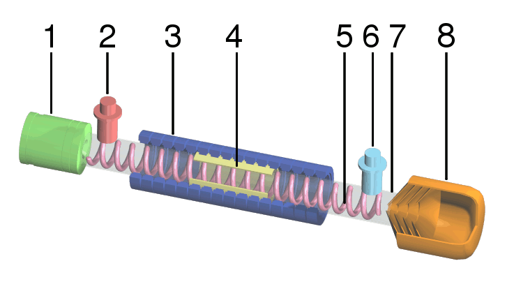
[edit]The TWT is an elongated vacuum tube with an electron gun (a heated cathode that emits electrons) at one end. A voltage applied across the cathode and anode accelerates the electrons towards the far end of the tube, and an external magnetic field around the tube focuses the electrons into a beam. At the other end of the tube the electrons strike the "collector", which returns them to the circuit.
Wrapped around the inside of the tube, just outside the beam path, is a helix of wire, typically oxygen-free copper. The RF signal to be amplified is fed into the helix at a point near the emitter end of the tube. The signal is normally fed into the helix via a waveguide or electromagnetic coil placed at one end, forming a one-way signal path, a directional coupler.
By controlling the accelerating voltage, the speed of the electrons flowing down the tube is set to be similar to the speed of the RF signal running down the helix. The signal in the wire causes a magnetic field to be induced in the center of the helix, where the electrons are flowing. Depending on the phase of the signal, the electrons will either be sped up or slowed down as they pass the windings. This causes the electron beam to "bunch up", known technically as "velocity modulation". The resulting pattern of electron density in the beam is an analog of the original RF signal.
Because the beam is passing the helix as it travels, and that signal varies, it causes induction in the helix, amplifying the original signal. By the time it reaches the other end of the tube, this process has had time to deposit considerable energy back into the helix. A second directional coupler, positioned near the collector, receives an amplified version of the input signal from the far end of the RF circuit. Attenuators placed along the RF circuit prevent the reflected wave from traveling back to the cathode.
Higher powered helix TWTs usually contain beryllium oxide ceramic as both a helix support rod and in some cases, as an electron collector for the TWT because of its special electrical, mechanical, and thermal properties.[4][5]
Comparison
[edit]
There are a number of RF amplifier tubes that operate in a similar fashion to the TWT, known collectively as velocity-modulated tubes. The best known example is the klystron. All of these tubes use the same basic "bunching" of electrons to provide the amplification process, and differ largely in what process causes the velocity modulation to occur.
In the klystron, the electron beam passes through a hole in a resonant cavity which is connected to the source RF signal. The signal at the instant the electrons pass through the hole causes them to be accelerated (or decelerated). The electrons enter a "drift tube" in which faster electrons overtake the slower ones, creating the bunches, after which the electrons pass through another resonant cavity from which the output power is taken. Since the velocity sorting process takes time, the drift tube must often be several feet long.
In comparison, in the TWT the acceleration is caused by the interactions with the helix along the entire length of the tube. This allows the TWT to have a very low noise output, a major advantage of the design. More usefully, this process is much less sensitive to the physical arrangement of the tube, which allows the TWT to operate over a wider variety of frequencies. TWT's are generally at an advantage when low noise and frequency variability are useful.[6][7]
Coupled-cavity TWT
[edit]Helix TWTs are limited in peak RF power by the current handling (and therefore thickness) of the helix wire. As power level increases, the wire can overheat and cause the helix geometry to warp. Wire thickness can be increased to improve matters, but if the wire is too thick it becomes impossible to obtain the required helix pitch for proper operation. Typically helix TWTs achieve less than 2.5 kW output power.
The coupled-cavity TWT overcomes this limit by replacing the helix with a series of coupled cavities arranged axially along the beam. This structure provides a helical waveguide, and hence amplification can occur via velocity modulation. Helical waveguides have very nonlinear dispersion and thus are only narrowband (but wider than klystron). A coupled-cavity TWT can achieve 60 kW output power.
Operation is similar to that of a klystron, except that coupled-cavity TWTs are designed with attenuation between the slow-wave structure instead of a drift tube. The slow-wave structure gives the TWT its wide bandwidth. A free electron laser allows higher frequencies.
Traveling-wave-tube amplifier
[edit]A TWT integrated with a regulated power supply and protection circuits is referred to as a traveling-wave-tube amplifier[8] (abbreviated TWTA and often pronounced "TWEET-uh"). It is used to produce high-power radio frequency signals. The bandwidth of a broadband TWTA can be as high as one octave,[citation needed] although tuned (narrowband) versions exist; operating frequencies range from 300 MHz to 50 GHz.
A TWTA consists of a traveling-wave tube coupled with its protection circuits (as in klystron) and regulated power supply electronic power conditioner (EPC), which may be supplied and integrated by a different manufacturer. The main difference between most power supplies and those for vacuum tubes is that efficient vacuum tubes have depressed collectors to recycle kinetic energy of the electrons, so the secondary winding of the power supply needs up to 6 taps of which the helix voltage needs precise regulation. The subsequent addition of a linearizer (as for inductive output tube) can, by complementary compensation, improve the gain compression and other characteristics of the TWTA; this combination is called a linearized TWTA (LTWTA, "EL-tweet-uh").
Broadband TWTAs generally use a helix TWT and achieve less than 2.5 kW output power. TWTAs using a coupled cavity TWT can achieve 15 kW output power, but at the expense of narrower bandwidth.
Invention, development and early use
[edit]The original design and prototype of the TWT was done by Andrei "Andy" Haeff c. 1931 while he was working as a doctoral student at the Kellogg Radiation Laboratory at Caltech. His original patent, "Device for and Method of Controlling High Frequency Currents", was filed in 1933 and granted in 1936.[9][10]
The invention of the TWT is often attributed to Rudolf Kompfner in 1942–1943. In addition, Nils Lindenblad, working at RCA (Radio Corporation of America) in the USA also filed a patent for a device in May 1940[11] that was remarkably similar to Kompfner's TWT.[12]: 2 Both of these devices were improvements over Haeff's original design as they both used the then newly invented precision electron gun as the source of the electron beam and they both directed the beam down the center of the helix instead of outside of it. These configuration changes resulted in much greater wave amplification than Haeff's design as they relied on the physical principles of velocity modulation and electron bunching.[10] Kompfner developed his TWT in a British Admiralty radar laboratory during World War II.[13] His first sketch of his TWT is dated November 12, 1942, and he built his first TWT in early 1943.[12]: 3 [14] The TWT was later refined by Kompfner,[14] John R. Pierce,[15] and Lester M. Winslow at Bell Labs. Note that Kompfner's US patent, granted in 1953, does cite Haeff's previous work.[10]
By the 1950s, after further development at the Electron Tube Laboratory at Hughes Aircraft Company in Culver City, California, TWTs went into production there, and by the 1960s TWTs were also produced by such companies as the English Electric Valve Company, followed by Ferranti in the 1970s.[16][17][18]
On July 10, 1962, the first communications satellite, Telstar 1, was launched with a 2 W, 4 GHz RCA-designed TWT transponder used for transmitting RF signals to Earth stations. Syncom 2 was successfully launched into geosynchronous orbit on July 26, 1963, with two 2 W, 1850 MHz Hughes-designed TWT transponders — one active and one spare.[19][20]
Uses
[edit]TWTAs are commonly used as amplifiers in satellite transponders, where the input signal is very weak and the output needs to be high power.[21] TWTAs used in satellite communications are considered as reliable choices and tend to live beyond their expected lifetime of 15-20 years.[22]
A TWTA whose output drives an antenna is a type of transmitter. TWTA transmitters are used extensively in radar, particularly in airborne fire-control radar systems, and in electronic warfare and self-protection systems.[23] In such applications, a control grid is typically introduced between the TWT's electron gun and slow-wave structure to allow pulsed operation. The circuit that drives the control grid is usually referred to as a grid modulator.
TWTAs have found applications in a number of spacecraft, including all five of the space probes that have achieved the escape velocity to leave the Solar System.[24][25] For example, dual redundant 12-watt X-band TWTAs are mounted on the body under the dish of the New Horizons spacecraft,[26] which visited Pluto in 2015, then Kuiper belt object 486958 Arrokoth in 2019 to return data at a distance of 43.4 AU from the Sun. Launched in 2021, James Webb Space Telescope makes use of Ka-band TWTs.[25]
Historical notes
[edit]A TWT has sometimes been referred to as a "traveling-wave amplifier tube" (TWAT),[27] although this term was never widely adopted. "TWT" has been pronounced by engineers as "twit",[28] and "TWTA" as "tweeta".[29]
See also
[edit]References
[edit]- ^ Electronics World + Wireless World. Reed Business Pub. 1991. p. 66.
- ^ a b c d e f g Gilmour, A. S. (2011). Klystrons, Traveling Wave Tubes, Magnetrons, Crossed-Field Amplifiers, and Gyrotrons. Artech House. pp. 317–18. ISBN 978-1608071852.
- ^ a b c d e Whitaker, Jerry C. (2002). The RF Transmission Systems Handbook. CRC Press. pp. 8.14 – 8.16. ISBN 1420041134.
- ^ 1997 Industrial Assessment of the Microwave Power Tube Industry - US Department of Defense [1]
- ^ Beryllium Oxide Properties
- ^ "Traveling Wave Tube"
- ^ "Velocity-modulated Tubes"
- ^ John Everett (1992). Vsats: Very Small Aperture Terminals. IET. ISBN 0-86341-200-9.
- ^ US 2064469, Haeff, Andrew V., "Device for and method of controlling high frequency currents", published 1936-12-15, assigned to Radio Corporation of America
- ^ a b c Copeland, Jack; Haeff, Andre A. (September 2015). "The True History of the Traveling Wave Tube". IEEE Spectrum. 52 (9): 38–43. doi:10.1109/MSPEC.2015.7226611. S2CID 36963575.
- ^ US 2300052, Lindenblad, Nils E., "Electron discharge device system", published 1942-10-27, assigned to Radio Corporation of America
- ^ a b Gilmour, A. S. (1994). Principles of traveling wave tubes. Artech House Radar Library. Boston: Artech House. pp. 2–3. ISBN 978-0-890-06720-8.
- ^ Shulim E. Tsimring (2007). Electron beams and microwave vacuum electronics. John Wiley and Sons. p. 298. ISBN 978-0-470-04816-0.
- ^ a b Kompfner, Rudolf (1964). The Invention of the Traveling-Wave Tube. San Francisco Press.
- ^ Pierce, John R. (1950). Traveling-Wave Tubes. D. van Nostrand Co.
- ^ Fire Direct Web site Archived 2009-09-23 at the Wayback Machine. Accessed 2 July 2008
- ^ "TWT - Travelling Wave Tubes". Archived from the original on 2008-09-19. Retrieved 2008-07-08.
- ^ Griffiths, Hugh (September 1980). "Travelling Wave Tube Amplifiers". RadCom. Retrieved 2015-07-15.
- ^ Zimmerman, Robert (Fall 2000). "TELSTAR". Invention and Technology Magazine. 16 (2). American Heritage. Archived from the original on October 13, 2007. Retrieved 2 July 2008.
- ^ Pond, Norman H. (2008). The Tube Guys. West Plains, Missouri: Russ Cochran. p. 328. ISBN 978-0-9816923-0-2. Archived from the original on June 19, 2010.
- ^ Dennis Roddy (2006). Satellite Communications. McGraw-Hill Professional. ISBN 0-07-146298-8.
- ^ Lohmeyer, Whitney Q.; Aniceto, Raichelle J.; Cahoy, Kerri L. (2016). "Communication satellite power amplifiers: current and future SSPA and TWTA technologies". International Journal of Satellite Communications and Networking. 34 (2): 95–113. doi:10.1002/sat.1098. hdl:1721.1/110897.
- ^ L. Sivan (1994). Microwave Tube Transmitters. Springer. ISBN 0-412-57950-2.
- ^ Ludwig, Roger; Taylor, Jim (March 2002). "Voyager Telecommunications" (PDF). DESCANSO Design and Performance Summary Series. Retrieved 7 May 2024.
- ^ a b Minenna, Damien F.G.; André, Frédéric; Elskens, Yves; Auboin, Jean-François; Doveil, Fabrice; Puech, Jérôme; Duverdier, Elise (2019). "The traveling-wave tube in the history of telecommunication". Eur. Phys. J. H. 44 (1): 1–36. arXiv:1803.11497. Bibcode:2019EPJH...44....1M. doi:10.1140/epjh/e2018-90023-1.
- ^ DeBoy, Christopher C.; et al. (2004). "The RF telecommunications system for the New Horizons mission to Pluto". 2004 IEEE Aerospace Conference Proceedings (IEEE Cat. No.04TH8720). Vol. 3. pp. 1463–1478. doi:10.1109/AERO.2004.1367922. ISBN 0-7803-8155-6.
- ^ "Military Acronyms, Initialisms, and Abbreviations". Federation of American Scientists. Archived from the original on 2007-10-21.
- ^ Henry W. Cole (1985). Understanding Radar. Collins. ISBN 9780003830583.
- ^ Mark Williamson (1990). Dictionary of Space Technology. A. Hilger. ISBN 0852743394.
Further reading
[edit]- Copeland, Jack; Haeff, Andre A. (September 2015). "The True History of the Traveling Wave Tube".
- Armstrong, Carter M; (November 2015). "The Quest for the Ultimate Vacuum Tube". IEEE Spectrum; [2]
External links
[edit]- Memorial page, with photo of John Pierce holding a TWT
- Nyquist page, with photo of Pierce, Kompfner, and Nyquist in front of TWT calculations on blackboard
- TMD Travelling Wave Tubes, Information & PDF data sheets.
- Flash animation showing the operation of a traveling wave tube (TWT) and its internal construction
Traveling-wave tube
View on GrokipediaFundamentals
Basic Principle
A traveling-wave tube (TWT) operates on principles rooted in vacuum electronics and electromagnetic wave propagation. Vacuum tube fundamentals involve thermionic emission from a cathode to generate free electrons, which are then accelerated by a high-voltage electric field to form a focused beam with uniform velocity in a vacuum environment, minimizing collisions and enabling high-speed transport. Electromagnetic waves in conventional waveguides propagate with phase velocities near or exceeding the speed of light, making direct energy exchange with slower electron beams impractical due to velocity mismatch. To overcome this, TWTs incorporate slow-wave structures that modify wave propagation, allowing controlled interaction between the beam and radiofrequency (RF) signals.[6] The core principle of the TWT is the synchronization of the electron beam velocity with the phase velocity of the RF wave, achieved through the dispersion relation of the slow-wave structure. The dispersion relation describes how the angular frequency relates to the propagation constant , yielding , which is engineered to approximate (typically 0.1–0.3 times the speed of light) by introducing periodicity or meandering paths that effectively lengthen the wave's travel distance. This synchronism ensures prolonged overlap between the beam and the axial electric field component of the RF wave, facilitating continuous energy transfer without reflection, unlike resonant cavities in klystrons. For instance, structures like the helix provide a nearly dispersionless phase velocity across a wide bandwidth, enabling broadband amplification.[1][4] Upon entering the interaction region, the tangential RF electric field imparts a small velocity modulation to the electrons, initiating the bunching process. Electrons encountering the field's positive half-cycle accelerate slightly, while those in the negative half decelerate, causing a phase-dependent density variation: faster electrons overtake slower ones, forming dense bunches that align with the RF wave's crests where the field reinforces energy extraction. This ballistic bunching converts the beam's kinetic energy into electromagnetic energy, progressively amplifying the wave's amplitude along the tube length. Space-charge effects, stemming from Coulomb repulsion within the electron cloud, counteract this by inducing transverse and longitudinal forces that debunch the electrons and limit interaction efficiency, particularly at high beam currents; these effects broaden the effective plasma frequency and are mitigated through beam focusing.[7][8] J. R. Pierce's foundational small-signal theory models this beam-wave interaction using linearized equations for the electron motion and circuit wave, assuming synchronism and neglecting higher-order nonlinearities. The theory couples the AC components of beam current and voltage to the circuit voltage via interaction impedance, leading to a cubic dispersion equation for the propagation constants of the three resultant modes (two attenuating and one growing). The growing mode yields an approximate power gain of dB, where is the Pierce gain parameter—defined as , with the cold circuit interaction impedance, the beam current, and the beam voltage—and is the number of guide wavelengths (/, with the interaction length). This formula approximates the amplification in the linear regime, with typical values of 0.01–0.15 determining the tube's inherent gain potential, independent of input power.[9][1]Key Components
The electron gun in a traveling-wave tube (TWT) generates and accelerates a focused beam of electrons to interact with the radiofrequency (RF) signal. It typically employs a thermionic cathode, often an oxide-coated dispenser type, to emit electrons through thermal emission, which are then accelerated by a high-voltage anode to achieve the desired beam velocity.[10] The Pierce gun design, a convergent type, is widely used for its ability to produce a laminar, space-charge-limited flow with minimal emittance, ensuring efficient beam formation.[11] Beam focusing is achieved via periodic permanent magnet (PPM) or solenoid magnetic fields, which confine the electrons to a narrow path along the tube axis, preventing divergence and maximizing interaction efficiency.[10] The slow-wave structure (SWS) is the core component that enables continuous interaction between the electron beam and the RF wave by reducing the phase velocity of the electromagnetic wave to approximately match the electron beam velocity (). This velocity synchronization allows the slower-moving electrons to exchange energy with the faster wave over an extended length, facilitating amplification without the need for discrete bunching stages.[12] Common SWS materials include metals like copper or molybdenum for low loss and high thermal conductivity, with the structure's geometry tailored to support a dominant forward-propagating mode while attenuating backward waves.[13] Attenuators are integrated into the SWS to absorb reflected RF energy and prevent regenerative oscillations that could destabilize the amplifier. These are typically lossy dielectric or metallic coatings, such as carbon-based materials on support rods, placed periodically along the interaction region to ensure unidirectional wave propagation and suppress multipactor effects.[14] The electron collector, located at the tube's output end, captures the spent, velocity-modulated beam after energy transfer to the RF wave, often designed as a multistage depressed collector to recover residual kinetic energy and improve overall efficiency by up to 90% in high-power applications.[15] The entire TWT assembly is enclosed in a vacuum envelope to maintain high vacuum conditions essential for electron beam stability and to prevent arcing, typically constructed from insulating materials like glass or ceramic (e.g., alumina) for high-voltage standoff and thermal management.[4] RF input and output couplers facilitate signal injection and extraction, commonly using non-contact waveguide directional couplers that electromagnetically launch the input RF into the SWS and couple the amplified output without direct electrical connection to the circuit, ensuring broadband matching and minimal insertion loss.[16]Types
Helix TWT
The helix traveling-wave tube (TWT) utilizes a helical slow-wave structure formed by a tightly wound wire or metal tape, which reduces the phase velocity of the propagating electromagnetic wave to synchronize with the electron beam for efficient amplification. This geometry, derived from a single-wire transmission line, features a cylindrical helix with parameters including diameter, pitch angle, and axial length, where the phase velocity is slowed by a factor approximately equal to the sine of the pitch angle relative to the speed of light.[17][1] The helix supports forward space-harmonic waves that satisfy the dispersion relation , exhibiting nearly non-dispersive behavior up to the cutoff frequency, where the phase velocity remains constant over a wide frequency range. This characteristic enables the helix TWT to achieve a fractional bandwidth of up to 100% (one octave) or more, with typical values exceeding 50% in many designs, providing advantages for broadband signal amplification compared to more dispersive structures.[18] In construction, the helix is typically wound from a flat metal tape and supported longitudinally by three or more dielectric rods within a metallic barrel to prevent deformation and ensure mechanical stability; common support methods include the barb technique, where rods are notched to hold the helix, and the tape method, involving adhesive or friction-based fixation. For high-power variants, the structure incorporates cooling provisions, such as thermal conduction through the barrel or integrated heat sinks, to dissipate heat generated during operation and prevent performance degradation.[17][1] Relative to coupled-cavity TWTs, the helix design delivers higher gain per unit length due to its continuous interaction path but exhibits lower power handling, limited by the thinner wire structure and higher risk of dielectric breakdown in the support rods.[1][17]Coupled-Cavity TWT
The coupled-cavity traveling-wave tube (TWT) features a slow-wave structure composed of a series of resonant cavities, typically pillbox-shaped with doubly reentrant drift tubes, coupled sequentially by irises that allow the electromagnetic wave to propagate along the electron beam path.[19] This design enables operation in the π-mode, where the phase shift per cavity is approximately π radians, ensuring synchronism between the decelerating electron beam and the RF wave for efficient energy transfer.[19] The cavities are often machined from high-conductivity materials like copper or Glidcop to minimize losses, with the beam passing through central apertures in the drift tubes.[20] This configuration supports high power handling, capable of delivering up to kilowatts in continuous wave (CW) operation, facilitated by larger electron beam diameters—such as 0.6 mm or more—and enhanced heat dissipation through all-metal construction and radiation-cooled collectors.[21][20] For instance, designs have achieved 1.5 kW average output power in X-band with variable beam disk diameters along the tube length to optimize focusing and interception.[22] At saturation, peak powers exceed 200 W at 12 GHz with beam voltages around 11 kV and currents of 70 mA, while collector temperatures remain below 400°C under 90 W dissipation.[21][19] Bandwidth is inherently limited by the resonant nature of the cavities, typically ranging from 10-20% of the center frequency, such as 1300 MHz cold bandwidth (about 10%) at 12 GHz or 170 MHz operational bandwidth.[19][21] Tuning methods, including movable shorts or stubs in sever sections, allow adjustment of the phase velocity to maintain synchronism across the band, though fabrication tolerances and beam quality can further constrain performance to as low as 30 MHz in high-frequency W-band examples.[19][20] In pulsed systems, coupled-cavity TWTs incorporate drift tubes to guide the beam between interaction sections and severing attenuators—often silicon carbide loads—to isolate cavities and suppress oscillations like backward-wave modes, enabling reliable high-power pulses for applications such as radar and satellite communications.[19] These features support pulse lengths of 3 µs at repetition rates up to 1 Hz in W-band designs, with gains over 20 dB.[20][19]Operation
Amplification Process
The amplification process in a traveling-wave tube (TWT) begins with the coupling of the radiofrequency (RF) input signal into the slow-wave structure, where it propagates alongside a focused electron beam generated by an electron gun. The input signal, typically introduced via a waveguide-to-helix transition or similar coupler, excites an electromagnetic wave whose phase velocity is slowed to match the beam's velocity, enabling continuous interaction along the tube's length. This synchronization is crucial for the subsequent modulation of the electron beam. As the RF wave's axial electric field interacts with the electron beam, velocity modulation occurs: electrons entering the decelerating phase of the field slow down, while those in the accelerating phase speed up, creating periodic variations in electron velocity. This initial velocity bunching evolves into density bunching as faster electrons catch up to slower ones, forming dense electron clusters separated by sparser regions, which effectively modulate the beam's current density. The bunched electrons then transfer kinetic energy to the co-propagating RF wave during the growing wave interaction, where the wave amplitude increases exponentially due to the cumulative energy exchange over the interaction length, often achieving gains of 30–60 dB. Finally, the amplified wave is extracted at the output end through a similar coupling structure, such as a waveguide transition, while the spent electron beam is collected by an electrode. In the small-signal regime, where input power is low, the interaction remains linear, with amplification governed by exponential growth proportional to the tube length and beam parameters, as described in early theoretical models. As input power increases, the process transitions to the large-signal regime, where non-linear effects dominate: electron bunches catch up more aggressively, leading to harmonic generation (primarily second harmonics) and eventual saturation, where further input power yields minimal output increase due to disrupted beam-wave synchronism and energy transfer limits. Saturation typically reduces gain by 4–6 dB compared to small-signal predictions and can introduce amplitude-to-phase conversion. To prevent feedback and oscillations in multi-stage or high-gain TWT designs, lossy attenuators—such as dielectric or resistive materials inserted along the slow-wave circuit—absorb reflected waves and sever the structure into isolated sections, ensuring unidirectional amplification without parasitic backward-wave interactions. Noise figure considerations arise primarily from the velocity modulation process, where shot noise and thermal fluctuations in the electron beam contribute to minimum achievable noise levels of around 3–6 dB in optimized low-noise TWTs, outperforming many other microwave amplifiers due to the noise being inherent to the beam's modulation rather than added externally.[23]Performance Characteristics
Traveling-wave tubes (TWTs) typically achieve power gains in the range of 30 to 60 dB, with helix TWTs often providing stable gain exceeding 60 dB over bandwidths of approximately 30%.[4] For helix designs, bandwidths commonly span 10-50% of the center frequency, enabling broad operational ranges suitable for wideband applications, while more specialized configurations like coupled-cavity TWTs may limit bandwidth to around 20% at higher voltages.[4] The interaction impedance, a key parameter characterizing the coupling between the electron beam and the RF wave, is defined as , where is the axial electric field amplitude, is the propagation constant, and is the RF power flow along the circuit; this quantity influences the gain and synchronism in the beam-wave interaction.[4] Electronic efficiency in TWTs, defined as , where and are the output and input RF powers, respectively, and is the electron beam power, typically ranges from 10-20% in standard designs.[24] Overall efficiency, which accounts for RF output relative to total DC input including collector losses, can reach 44-55% through the use of multi-stage depressed collectors that recover residual beam kinetic energy.[24] For instance, in a 20 GHz space communication TWT, electronic efficiency of about 17% was measured alongside an overall efficiency of 54.6%.[24] Intermodulation distortion arises in TWTs under multi-tone operation due to nonlinear beam-wave interactions, generating unwanted products that degrade signal quality.[25] The third-order intercept point (IP3), a measure of linearity, is typically around 10 dB above the 1 dB compression point, indicating the extrapolated input power level where third-order products would equal the fundamental; for two-tone tests, carrier-to-third-order intermodulation (C/3IM) ratios start near 9 dB at saturation and improve to over 20 dB in the linear regime.[25] In high-power pulsed TWT systems, phase stability is critical for coherent applications, often quantified via AM-to-PM conversion, which measures phase shifts with varying drive levels and is minimized to below 5°/dB in optimized designs.[4] Pulse droop, the gradual reduction in output power during long pulses due to beam current variations or thermal effects, is typically limited to less than 1 dB over pulse lengths of several microseconds in modern high-power systems to maintain consistent performance.[26]History
Invention and Early Development
The foundational concepts for the traveling-wave tube (TWT) emerged from early investigations into velocity modulation of electron beams for microwave generation. In 1935, Agnesa Arsenjewa-Heil and Oskar Heil published a pioneering paper in Zeitschrift für Physik, introducing a method to produce short, undamped electromagnetic waves of high intensity by modulating the velocity of an electron stream in a high-frequency electric field, which provided key theoretical principles for subsequent microwave devices including the TWT.[27] Independent early inventions of TWT-like devices occurred in the 1930s. Andrei Haeff, working at Caltech, developed a prototype in 1931–1932 where an electron beam interacted progressively with a traveling electromagnetic wave along a transmission line, filing U.S. Patent No. 2,064,469 in October 1933 for this low-noise microwave amplifier concept.[2] Nils Lindenblad at RCA proposed an improved design in 1940, patenting a structure with periodic loading to enhance wave-beam synchronism (U.S. Patent No. 2,300,052).[2] The configuration of the modern helix TWT was invented by Rudolf Kompfner in 1942 at the University of Birmingham, UK, where he introduced a helical conductor as a slow-wave structure to match the phase velocity of the electromagnetic wave to that of the electron beam, enabling continuous interaction and amplification.[28] Kompfner, an Austrian-born physicist who had emigrated to Britain in 1933 to escape Nazi persecution, demonstrated the first working helix TWT in early 1943.[29] During World War II, British efforts focused on TWTs for radar amplifiers amid the push for centimeter-wave technology, with Kompfner's device showing promise for broadband, low-noise performance in military applications.[2] Post-war declassification enabled broader development. Kompfner filed a UK patent for the helix TWT in June 1944 (No. 623,537), followed by a U.S. filing in March 1948 (issued as No. 2,630,544 in 1953).[2][30] His seminal paper, "The Traveling-Wave Tube as an Amplifier at Microwaves," appeared in 1947, detailing the device's principles and experimental results.[31][32] In the U.S., Bell Laboratories pursued TWT refinement starting in 1948, producing the first operational sealed-off tubes by the late 1940s for radar and communication uses. Early theoretical analysis at Bell Labs, led by John R. Pierce, introduced gain parameters in 1948–1949 to model amplification, incorporating space-charge and cathode effects for practical design.[33]Key Milestones and Advancements
In the 1950s, theoretical advancements solidified the foundation for practical TWT implementation, with John R. Pierce developing the influential three-wave theory that modeled the interaction between the electron beam and electromagnetic waves, enabling more precise design of amplifier performance.[1] This theory, detailed in Pierce's seminal 1950 work, addressed nonlinear behaviors and power output limitations, facilitating the transition from experimental devices to reliable systems.[34] Concurrently, Varian Associates pioneered the production of the first commercial TWTs, introducing helix-based models that achieved broadband amplification up to several watts in the microwave range, marking the device's entry into telecommunications and radar applications.[35] During the 1960s and 1970s, coupled-cavity TWT designs emerged as a key innovation for high-power operations, offering improved heat dissipation and structural integrity over helical variants for pulsed applications. These structures enabled megawatt-level peak powers, as demonstrated in a 1962 X-band amplifier achieving 1 MW output with 18% bandwidth, suitable for demanding accelerator and radar systems.[36] Such advancements found application at facilities like the Stanford Linear Accelerator Center, where coupled-cavity TWTs supported high-pulse RF amplification for particle acceleration experiments, contributing to megawatt-scale beam driving in the era's linear collider prototypes.[37] The 1980s and 2000s saw significant miniaturization efforts tailored for space environments, with TWTs integrated into traveling-wave tube amplifiers (TWTAs) for satellite transponders, reducing mass and volume while maintaining kilowatt-level outputs essential for long-haul communications.[38] A pivotal shift involved replacing bulky solenoid focusing with periodic permanent magnet (PPM) systems, which used alternating magnet rings to confine electron beams more efficiently, cutting power consumption by up to 90% and enabling compact designs weighing under 5 kg for orbital use.[3] These PPM-focused TWTAs became standard in geostationary satellites, supporting multi-gigabit data links with efficiencies exceeding 50%.[39] Post-2010 developments have emphasized efficiency and novel structures, including the integration of gallium nitride (GaN) elements in hybrid TWTA drivers to boost overall system efficiency beyond 60% by enhancing solid-state pre-amplification stages before vacuum tube output.[40] Metamaterial-based slow-wave structures have further advanced performance, with all-metal designs in 2015 enabling higher interaction impedance and reduced ohmic losses for millimeter-wave TWTs operating above 100 GHz with gains over 40 dB.[41] For deep-space missions, NASA has qualified advanced TWTAs in the 2020s, such as X-band models for the Psyche mission launched in October 2023, delivering 100 W RF output with over 50% efficiency to support high-data-rate telemetry from asteroid encounters.[42]Applications
Radar and Military Systems
Traveling-wave tubes (TWTs) play a critical role in airborne radar systems, particularly X-band configurations used for search and tracking missions, where their high-gain and broadband capabilities enable reliable detection in dynamic environments. For instance, compact pulsed X-band helix TWTs have been developed specifically for airborne radar applications, delivering efficient amplification in weight-constrained platforms to support fire-control and surveillance functions.[43] These devices are integrated into pod-mounted systems, such as the dB-3708P1 TWTA, which provides pulsed operation for threat simulation and radar enhancement in military aircraft.[44] In shipborne radars, X-band TWTs are employed for air and surface tracking, offering robust performance against environmental challenges like vibration and salt exposure. The U.S. Navy's AN/SPQ-9B radar utilizes TWT components to achieve wideband amplification, enabling horizon-search capabilities for detecting low-flying aircraft and surface vessels over extended ranges.[45] Coupled-cavity TWTs are particularly suited for these high-power shipboard demands due to their ability to handle pulsed outputs while maintaining stability in maritime conditions.[46] Electronic warfare systems rely on broadband helix TWTs for jamming and countermeasures, providing wide frequency coverage to disrupt enemy radar signals effectively. These TWTs are integral to airborne ECM pods, where their instantaneous bandwidth—often exceeding an octave—allows for rapid adaptation to multiple threats, as demonstrated in historical and ongoing deployments for radar deception and suppression.[47] In jamming applications, helix TWTs deliver reliable RF power across L- to Ku-bands, supporting automated defeat of hostile tracking radars in contested airspace.[48] Compact TWTs are utilized in missile seekers for active radar homing, where space and power constraints necessitate miniaturized, high-efficiency designs. These devices amplify seeker signals in terminal guidance phases, enabling precise target acquisition in beyond-visual-range engagements, as seen in early active radar-seeking missile systems.[49] For example, upgrades to systems like the AIM-120 AMRAAM have incorporated advanced compact TWTs to enhance seeker performance, though specifics remain classified; their role focuses on providing the necessary RF amplification for hit-to-kill accuracy.[50] Military radar applications demand high peak power from TWTs during pulsed operation to achieve long-range detection, with capabilities reaching up to 100 kW or more to illuminate distant targets. This pulsed mode, often with duty cycles around 10%, ensures efficient energy use while maximizing signal strength for surveillance and tracking in radar systems.[51] Such power levels are essential for overcoming atmospheric attenuation in X-band operations, supporting both airborne and shipborne platforms in demanding defense scenarios.[52]Satellite and Communication Systems
Traveling-wave tube amplifiers (TWTAs) serve as high-power amplifiers in satellite transponders, particularly in Ku- and Ka-band frequencies, enabling efficient signal amplification for broadband communication services. In geostationary satellites like those in the Intelsat series, TWTAs provide output powers ranging from tens to hundreds of watts to support transponder channels that relay television broadcasts, internet, and telephony across global coverage areas. For instance, early Intelsat satellites such as Intelsat 1 (Early Bird) utilized 6 W TWTs for initial commercial communications, while modern iterations incorporate higher-power units, such as those delivering tens to hundreds of watts in Ka-band for enhanced data throughput.[38] These amplifiers are integral to the satellite's payload, where their wide bandwidth—often exceeding 500 MHz—facilitates multiple frequency channels within the allocated spectrum.[53] In terrestrial communication systems, TWTs support high-effective isotropic radiated power (EIRP) microwave relay stations, which form backbone networks for long-haul data transmission. Historically, TWT-based amplifiers powered microwave ground relay stations that enabled transcontinental telephony and early television distribution by providing reliable amplification at microwave frequencies. In contemporary 5G backhaul applications, emerging TWT designs address the demand for high-capacity millimeter-wave links, such as W-band (92-95 GHz) systems that achieve multi-gigabit rates over extended distances. For example, folded waveguide TWTs developed under the European Horizon 2020 TWEETHER project enable novel high-capacity backhaul networks by delivering watt-level power at millimeter waves, outperforming solid-state alternatives in scenarios requiring extended range and high EIRP.[54][55] For deep-space missions, low-noise TWTs are essential for transmitting scientific data over vast distances, with NASA's Voyager probes exemplifying their longevity. The Voyager spacecraft employ X-band TWT transmitters, such as the Watkins Johnson model, which have operated reliably for over 45 years, accumulating more than 500,000 hours of service with minimal failures—one X-band TWTA failure after 10 years. Similarly, the James Webb Space Telescope (JWST), launched in 2021, utilizes Ka-band TWTAs to support high-data-rate downlinks of up to 28 Mbps, incorporating post-2020 enhancements like improved efficiency collectors for sustained performance in the harsh space environment. These low-noise designs minimize added signal distortion, crucial for preserving the integrity of faint astronomical observations transmitted from the L2 Lagrange point.[56][57] TWTAs in satellite and deep-space applications achieve exceptional reliability through radiation hardening and robust design, with mean time between failures (MTBF) often exceeding 100,000 hours. Radiation hardening involves selecting materials resistant to cosmic rays and solar particles, such as specialized cathodes and collectors, ensuring operation in vacuum and extreme temperatures. For Ku-band space TWTAs, MTBF values reach approximately 305,000 hours at 90% confidence, while C-band variants exceed 1.8 million hours, supporting mission durations of 10-15 years or more. These metrics underscore the TWT's role in minimizing satellite downtime and maximizing operational lifespan in orbit.[56][58]Advantages and Limitations
Operational Benefits
Traveling-wave tubes (TWTs) offer exceptional high gain and output power combined with wide instantaneous bandwidth, often exceeding 1 GHz at levels above 1 kW, surpassing the capabilities of solid-state power amplifiers (SSPAs) that typically require stacking multiple devices to reach comparable performance in a single unit.[59][60] For instance, a Ka-band continuous-wave TWT achieves a 1-dB bandwidth of 6 GHz (26–32 GHz) with saturated output power over 2 kW, demonstrating the device's ability to handle broadband high-power amplification without the complexity of multi-device SSPA arrays.[59] Similarly, an X-band ring-bar TWT delivers over 5 kW output with 46 dB gain across a 3.6 GHz bandwidth (9.1–12.7 GHz), highlighting its utility in applications demanding both power and frequency agility.[61] TWTs provide superior phase linearity, characterized by low AM-PM conversion rates typically under 6°/dB, which ensures minimal phase distortion under varying input amplitudes and supports precise beam control in phased array radars.[62][63] This low conversion factor, often optimized to below 5.5°/dB through structural enhancements like folded waveguides, maintains signal integrity for array-based systems where phase errors could degrade performance.[62] In terms of ruggedness, TWTs excel in harsh operational environments, withstanding temperature extremes from -55°C to +80°C (extendable to +100°C in advanced designs) and high vibration levels common in military platforms, due to their robust vacuum tube construction and efficient thermal management.[10][4] Coupled-cavity TWT variants, in particular, offer enhanced mechanical stability and heat dissipation compared to helix types, enabling reliable operation under shock and vibration stresses in defense systems.[4][64] Compared to other microwave tubes, TWTs strike a favorable balance in power-bandwidth trade-offs, providing broader bandwidth at high power levels without the resonant structure limitations of alternatives.| Device | Typical Power Output | Bandwidth Capability | Key Trade-offs |
|---|---|---|---|
| TWT | 1 kW–500 kW (peak) | >30% (up to octave) | High gain and broadband amplification; suitable for wideband RF signals |
| Klystron | Up to MW (CW/peak) | Narrow (~1–10%) | Excellent efficiency and power at fixed frequencies; limited tuning range |
| Magnetron | kW–MW (pulsed) | Narrow (fixed freq) | Compact and cost-effective oscillator; poor linearity and bandwidth |
| Gyrotron | MW (at mm-waves) | Moderate (10–20%) | High power in high-frequency regimes; complex magnetic requirements and narrower band than TWTs |