Recent from talks
Nothing was collected or created yet.
Fuse (electrical)
View on WikipediaA miniature time-delay 250 V fuse that will interrupt a 0.3 A current at after 100 s, or a 15 A current in 0.1 s. 32 mm (1+1⁄4 in) long. | |
| Component type | Passive |
|---|---|
| Working principle | Melting of internal conductor due to heat generated by excessive current flow |
| Electronic symbol | |
Electronic symbols for a fuse | |
In electronics and electrical engineering, a fuse is an electrical safety device that operates to provide overcurrent protection of an electrical circuit. Its essential component is a metal wire or strip that melts when too much current flows through it, thereby stopping or interrupting the current. It is a sacrificial device; once a fuse has operated, it is an open circuit, and must be replaced or rewired, depending on its type.
Fuses have been used as essential safety devices from the early days of electrical engineering. Today there are thousands of different fuse designs which have specific current and voltage ratings, breaking capacity, and response times, depending on the application. The time and current operating characteristics of fuses are chosen to provide adequate protection without needless interruption. Wiring regulations usually define a maximum fuse current rating for particular circuits. A fuse can be used to mitigate short circuits, overloading, mismatched loads, or device failure. When a damaged live wire makes contact with a metal case that is connected to ground, a short circuit will form and the fuse will melt.
A fuse is an automatic means of removing power from a faulty system, often abbreviated to ADS (automatic disconnection of supply). Circuit breakers have replaced fuses in many contexts, but have significantly different characteristics, and fuses are still used when space, resiliency or cost are significant factors.
History
[edit]| Electrical installations |
|---|
| Wiring practice by region or country |
| Regulation of electrical installations |
| Cabling and accessories |
| Switching and protection devices |
Louis Clément François Breguet recommended the use of reduced-section conductors to protect telegraph stations from lightning strikes; by melting, the smaller wires would protect apparatus and wiring inside the building.[1] A variety of wire or foil fusible elements were in use to protect telegraph cables and lighting installations as early as 1864.[2]
A fuse was patented by Thomas Edison in 1890 as part of his electric distribution system.[3]
Construction
[edit]A fuse consists of a metal strip or wire fuse element, of small cross-section compared to the circuit conductors, mounted between a pair of electrical terminals, and (usually) enclosed by a non-combustible housing. The fuse is arranged in series to carry all the charge passing through the protected circuit. The resistance of the element generates heat due to the current flow. The size and construction of the element is (empirically) determined so that the heat produced for a normal current does not cause the element to attain a high temperature. If too high of a current flows, the element rises to a higher temperature and either directly melts, or else melts a soldered joint within the fuse, opening the circuit.
The fuse element is made of zinc, copper, silver, aluminium,[citation needed] or alloys among these or other various metals to provide stable and predictable characteristics.[4][5] The fuse ideally would carry its rated current indefinitely, and melt quickly on a small excess. The element must not be damaged by minor harmless surges of current, and must not oxidize or change its behavior after possibly years of service.
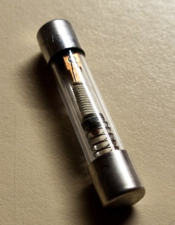
The fuse elements may be shaped to increase heating effect. In large fuses, current may be divided between multiple strips of metal. A dual-element fuse may contain a metal strip that melts instantly on a short circuit, and also contain a low-melting solder joint that responds to long-term overload of low values compared to a short circuit. Fuse elements may be supported by steel or nichrome wires, so that no strain is placed on the element, but a spring may be included to increase the speed of parting of the element fragments.
The fuse element may be surrounded by air, or by materials intended to speed the quenching of the arc. Silica sand or non-conducting liquids may be used.
Characteristics
[edit]Rated current IN
[edit]A maximum current that the fuse can continuously conduct without interrupting the circuit.
Time vs current characteristics
[edit]The speed at which a fuse blows depends on how much current flows through it and the material of which the fuse is made. Manufacturers can provide a plot of current vs time, often plotted on logarithmic scales, to characterize the device and to allow comparison with the characteristics of protective devices upstream and downstream of the fuse.
The operating time is not a fixed interval but decreases as the current increases. Fuses are designed to have particular characteristics of operating time compared to current. A standard fuse may require twice its rated current to open in one second, a fast-blow fuse may require twice its rated current to blow in 0.1 seconds, and a slow-blow fuse may require twice its rated current for tens of seconds to blow.
Fuse selection depends on the load's characteristics. Semiconductor devices may use a fast or ultrafast fuse as semiconductor devices heat rapidly when excess current flows. The fastest blowing fuses are designed for the most sensitive electrical equipment, where even a short exposure to an overload current could be damaging. Normal fast-blow fuses are the most general purpose fuses. A time-delay fuse (also known as an anti-surge or slow-blow fuse) is designed to allow a current which is above the rated value of the fuse to flow for a short period of time without the fuse blowing. These types of fuse are used on equipment such as motors, which can draw larger than normal currents for up to several seconds while coming up to speed.
The I2t value
[edit]
The I2t rating is related to the amount of energy let through by the fuse element when it clears the electrical fault. This term is normally used in short circuit conditions and the values are used to perform co-ordination studies in electrical networks. I2t parameters are provided by charts in manufacturer data sheets for each fuse family. For coordination of fuse operation with upstream or downstream devices, both melting I2t and clearing I2t are specified. The melting I2t is proportional to the amount of energy required to begin melting the fuse element. The clearing I2t is proportional to the total energy let through by the fuse when clearing a fault. The energy is mainly dependent on current and time for fuses as well as the available fault level and system voltage. Since the I2t rating of the fuse is proportional to the energy it lets through, it is a measure of the thermal damage from the heat and magnetic forces that will be produced by a fault end.
Breaking capacity
[edit]The breaking capacity is the maximum current that can safely be interrupted by the fuse. This should be higher than the prospective short-circuit current. Miniature fuses may have an interrupting rating only 10 times their rated current. Fuses for small, low-voltage, usually residential, wiring systems are commonly rated, in North American practice, to interrupt 10,000 amperes. Fuses for commercial or industrial power systems must have higher interrupting ratings, with some low-voltage current-limiting high interrupting fuses rated for 300,000 amperes. Fuses for high-voltage equipment, up to 115,000 volts, are rated by the total apparent power (megavolt-amperes, MVA) of the fault level on the circuit.
Some fuses are designated high rupture capacity (HRC) or high breaking capacity (HBC)[6] and are usually filled with sand or a similar material.[7]

Low-voltage high rupture capacity (HRC) fuses are used in the area of main distribution boards in low-voltage networks where there is a high prospective short circuit current. They are generally larger than screw-type fuses, and have ferrule cap or blade contacts. High rupture capacity fuses may be rated to interrupt current of 120 kA.
HRC fuses are widely used in industrial installations and are also used in the public power grid, e.g. in transformer stations, main distribution boards, or in building junction boxes and as meter fuses.
In some countries, because of the high fault current available where these fuses are used, local regulations may permit only trained personnel to change these fuses. Some varieties of HRC fuse include special handling features.
Rated voltage
[edit]The voltage rating of the fuse must be equal to or, greater than, what would become the open-circuit voltage. For example, a glass tube fuse rated at 32 volts would not reliably interrupt current from a voltage source of 120 or 230 V. If a 32 V fuse attempts to interrupt the 120 or 230 V source, an arc may result. Plasma inside the glass tube may continue to conduct current until the current diminishes to the point where the plasma becomes a non-conducting gas. Rated voltage should be higher than the maximum voltage source it would have to disconnect. Connecting fuses in series does not increase the rated voltage of the combination, nor of any one fuse.
Medium-voltage fuses rated for a few thousand volts are never used on low voltage circuits, because of their cost and because they cannot properly clear the circuit when operating at very low voltages.[8]
Voltage drop
[edit]The manufacturer may specify the voltage drop across the fuse at rated current. There is a direct relationship between a fuse's cold resistance and its voltage drop value.[clarification needed] Once current is applied, resistance and voltage drop of a fuse will constantly grow with the rise of its operating temperature until the fuse finally reaches thermal equilibrium. The voltage drop should be taken into account, particularly when using a fuse in low-voltage applications. Voltage drop often is not significant in more traditional wire type fuses, but can be significant in other technologies such as resettable (PPTC) type fuses.
Temperature derating
[edit]Ambient temperature will change a fuse's operational parameters. A fuse rated for 1 A at 25 °C may conduct up to 10% or 20% more current at −40 °C and may open at 80% of its rated value at 100 °C. Operating values will vary with each fuse family and are provided in manufacturer data sheets.
Markings
[edit]
Most fuses are marked on the body or end caps with markings that indicate their ratings. Surface-mount technology "chip type" fuses feature few or no markings, making identification very difficult.
Similar appearing fuses may have significantly different properties, identified by their markings. Fuse markings[9] will generally convey the following information, either explicitly as text, or else implicit with the approval agency marking for a particular type:
- Current rating of the fuse.
- Voltage rating of the fuse.
- Time-current characteristic; i.e. fuse speed.
- Approvals by national and international standards agencies.
- Manufacturer/part number/series.
- Interrupting rating (breaking capacity)
Packages and materials
[edit]
Fuses come in a vast array of sizes and styles to serve in many applications, manufactured in standardised package layouts to make them easily interchangeable. Fuse bodies may be made of ceramic, glass, plastic, fiberglass, molded mica laminates, or molded compressed fibre depending on application and voltage class.
Cartridge (ferrule) fuses have a cylindrical body terminated with metal end caps. Some cartridge fuses are manufactured with end caps of different sizes to prevent accidental insertion of the wrong fuse rating in a holder, giving them a bottle shape.
Fuses for low voltage power circuits may have bolted blade or tag terminals which are secured by screws to a fuseholder. Some blade-type terminals are held by spring clips. Blade type fuses often require the use of a special purpose extractor tool to remove them from the fuse holder.
Renewable fuses have replaceable fuse elements, allowing the fuse body and terminals to be reused if not damaged after a fuse operation.
Fuses designed for soldering to a printed circuit board have radial or axial wire leads. Surface mount fuses have solder pads instead of leads.
High-voltage fuses of the expulsion type have fiber or glass-reinforced plastic tubes and an open end, and can have the fuse element replaced.
Semi-enclosed fuses are fuse wire carriers in which the fusible wire itself can be replaced. The exact fusing current is not as well controlled as an enclosed fuse, and it is extremely important to use the correct diameter and material when replacing the fuse wire, and for these reasons these fuses are slowly falling from favour.
These are still used in consumer units in some parts of the world, but are becoming less common. While glass fuses have the advantage of a fuse element visible for inspection purposes, they have a low breaking capacity (interrupting rating), which generally restricts them to applications of 15 A or less at 250 VAC. Ceramic fuses have the advantage of a higher breaking capacity, facilitating their use in circuits with higher current and voltage. Filling a fuse body with sand provides additional cooling of the arc and increases the breaking capacity of the fuse. Medium-voltage fuses may have liquid-filled envelopes to assist in the extinguishing of the arc. Some types of distribution switchgear use fuse links immersed in the oil that fills the equipment.
Fuse packages may include a rejection feature such as a pin, slot, or tab, which prevents interchange of otherwise similar appearing fuses. For example, fuse holders for North American class RK fuses have a pin that prevents installation of similar-appearing class H fuses, which have a much lower breaking capacity and a solid blade terminal that lacks the slot of the RK type.
Dimensions
[edit]Fuses can be built with different sized enclosures to prevent interchange of different ratings of fuse. For example, bottle style fuses distinguish between ratings with different cap diameters. Automotive glass fuses were made in different lengths, to prevent high-rated fuses being installed in a circuit intended for a lower rating.
Special features
[edit]Glass cartridge and plug fuses allow direct inspection of the fusible element. Other fuses have other indication methods including:
- Indicating pin or striker pin — extends out of the fuse cap when the element is blown.
- Indicating disc — a coloured disc (flush mounted in the end cap of the fuse) falls out when the element is blown.
- Element window — a small window built into the fuse body to provide visual indication of a blown element.
- External trip indicator — similar function to striker pin, but can be externally attached (using clips) to a compatible fuse.
Some fuses allow a special purpose micro switch or relay unit to be fixed to the fuse body. When the fuse element blows, the indicating pin extends to activate the micro switch or relay, which, in turn, triggers an event.
Some fuses for medium-voltage applications use two or three separate barrels and two or three fuse elements in parallel.
Fuse standards
[edit]IEC 60269 fuses
[edit]
The International Electrotechnical Commission publishes standard 60269 for low-voltage power fuses. The standard is in four volumes, which describe general requirements, fuses for industrial and commercial applications, fuses for residential applications, and fuses to protect semiconductor devices. The IEC standard unifies several national standards, thereby improving the interchangeability of fuses in international trade. All fuses of different technologies tested to meet IEC standards will have similar time-current characteristics, which simplifies design and maintenance.
UL 248 fuses (North America)
[edit]In the United States and Canada, low-voltage fuses to 1 kV AC rating are made in accordance with Underwriters Laboratories standard UL 248 or the harmonized Canadian Standards Association standard C22.2 No. 248. This standard applies to fuses rated 1 kV or less, AC or DC, and with breaking capacity up to 200 kA. These fuses are intended for installations following Canadian Electrical Code, Part I (CEC), or the National Electrical Code, NFPA 70 (NEC).
The standard ampere ratings for fuses (and circuit breakers) in USA/Canada are considered 15, 20, 25, 30, 35, 40, 45, 50, 60, 70, 80, 90, 100, 110, 125, 150, 175, 200, 225, 250, 300, 350, 400, 450, 500, 600, 700, 800, 1000, 1200, 1600, 2000, 2500, 3000, 4000, 5000, and 6000 amperes. Additional standard ampere ratings for fuses are 1, 3, 6, 10, and 601.
UL 248 currently has 19 "parts". UL 248-1 sets the general requirements for fuses, while the latter parts are dedicated to specific fuses sizes (ex: 248-8 for Class J, 248-10 for Class L), or for categories of fuses with unique properties (ex: 248-13 for semiconductor fuses, 248-19 for photovoltaic fuses). The general requirements (248–1) apply except as modified by the supplemental part (240-x). For example, UL 248-19 allows photovoltaic fuses to be rated up to 1500 volts, DC, versus 1000 volts under the general requirements.
IEC and UL nomenclature varies slightly. IEC standards refer to a "fuse" as the assembly of a fusible link and a fuse holder. In North American standards, the fuse is the replaceable portion of the assembly, and a fuse link would be a bare metal element for installation in a fuse.
Automotive fuses
[edit]
Automotive fuses are used to protect the wiring and electrical equipment for vehicles. There are several different types of automotive fuses and their usage is dependent upon the specific application, voltage, and current demands of the electrical circuit. Automotive fuses can be mounted in fuse blocks, inline fuse holders, or fuse clips. Some automotive fuses are occasionally used in non-automotive electrical applications. Standards for automotive fuses are published by SAE International (formerly known as the Society of Automotive Engineers).
Automotive fuses can be classified into four distinct categories:
- Blade fuses
- Glass tube or Bosch type
- Fusible links
- Fuse limiters
Most automotive fuses rated at 32 volts are used on circuits rated 24 volts DC and below. Some vehicles use a dual 12/42 V DC electrical system[10] that will require a fuse rated at 58 V DC.
High voltage fuses
[edit]
Fuses are used on power systems up to 115,000 volts AC. High-voltage fuses are used to protect instrument transformers used for electricity metering, or for small power transformers where the expense of a circuit breaker is not warranted. A circuit breaker at 115 kV may cost up to five times as much as a set of power fuses, so the resulting saving can be tens of thousands of dollars.[citation needed]
In medium-voltage distribution systems, a power fuse may be used to protect a transformer serving 1–3 houses. Pole-mounted distribution transformers are nearly always protected by a fusible cutout, which can have the fuse element replaced using live-line maintenance tools.
Medium-voltage fuses are also used to protect motors, capacitor banks and transformers and may be mounted in metal enclosed switchgear, or (rarely in new designs) on open switchboards.
Expulsion fuses
[edit]Large power fuses use fusible elements made of silver, copper or tin to provide stable and predictable performance. High voltage expulsion fuses surround the fusible link with gas-evolving substances, such as boric acid. When the fuse blows, heat from the arc causes the boric acid to evolve large volumes of gases. The associated high pressure (often greater than 100 atmospheres) and cooling gases rapidly quench the resulting arc. The hot gases are then explosively expelled out of the end(s) of the fuse. Such fuses can only be used outdoors.


These type of fuses may have an impact pin to operate a switch mechanism, so that all three phases are interrupted if any one fuse blows.
High-power fuse means that these fuses can interrupt several kiloamperes. Some manufacturers have tested their fuses for up to 63 kA short-circuit current.
Comparison with circuit breakers
[edit]Fuses have the advantages of often being less costly and simpler than a circuit breaker for similar ratings. The blown fuse must be replaced with a new device which is less convenient than simply resetting a breaker and therefore likely to discourage people from ignoring faults. On the other hand, replacing a fuse without isolating the circuit first (most building wiring designs do not provide individual isolation switches for each fuse) can be dangerous in itself, particularly if the fault is a short circuit.
In terms of protection response time, fuses tend to isolate faults more quickly (depending on their operating time) than circuit breakers. A fuse can clear a fault within a quarter cycle of the fault current, while a circuit breaker may take around half to one cycle to clear the fault. The response time of a fuse can be as fast as 0.002 seconds, whereas a circuit breaker typically responds in the range of 0.02 to 0.05 seconds.
High rupturing capacity fuses can be rated to safely interrupt up to 300,000 amperes at 600 V AC. Special current-limiting fuses are applied ahead of some molded-case breakers to protect the breakers in low-voltage power circuits with high short-circuit levels.
Current-limiting fuses operate so quickly that they limit the total "let-through" energy that passes into the circuit, helping to protect downstream equipment from damage. These fuses open in less than one cycle of the AC power frequency; circuit breakers cannot match this speed.
Some types of circuit breakers must be maintained on a regular basis to ensure their mechanical operation during an interruption. This is not the case with fuses, which rely on melting processes where no mechanical operation is required for the fuse to operate under fault conditions.
In a multi-phase power circuit, if only one fuse opens, the remaining phases will have higher than normal currents, and unbalanced voltages, with possible damage to motors. Fuses only sense overcurrent, or to a degree, over-temperature, and cannot usually be used independently with protective relaying to provide more advanced protective functions, for example, ground fault detection.
Some manufacturers of medium-voltage distribution fuses combine the overcurrent protection characteristics of the fusible element with the flexibility of relay protection by adding a pyrotechnic device to the fuse operated by external protective relays.
For domestic applications, Miniature circuit breakers (MCB) are widely used as an alternative to fuses. Their rated current depend on the load current of the equipment to be protected and the ambient operational temperature. They are available in the following ratings: 6A, 10A, 16A, 20A, 25A, 32A, 45A, 50A, 63A, 80A, 100A, 125A.[11]
Fuse boxes
[edit]United Kingdom
[edit]In the UK, older electrical consumer units (also called fuse boxes) are fitted either with semi-enclosed (rewirable) fuses (BS 3036) or cartridge fuses (BS 1361). (Fuse wire is commonly supplied to consumers as short lengths of 5 A-, 15 A- and 30 A-rated wire wound on a piece of cardboard.) Modern consumer units usually contain miniature circuit breakers (MCBs) instead of fuses, though cartridge fuses are sometimes still used, as in some applications MCBs are prone to nuisance tripping.
Renewable fuses (rewirable or cartridge) allow user replacement, but this can be hazardous as it is easy to put a higher-rated or double fuse element (link or wire) into the holder (overfusing), or simply fitting it with copper wire or even a totally different type of conducting object (coins, hairpins, paper clips, nails, etc.) to the existing carrier. One form of fuse box abuse was to put a penny in the socket, which defeated overcurrent protection and resulted in a dangerous condition. Such tampering will not be visible without full inspection of the fuse. Fuse wire was never used in North America for this reason, although renewable fuses continue to be made for distribution boards.
- UK fuse boxes and rewirable fuses
-
MEM rewirable fuse box with four rewirable fuse holders (two 30 A and two 15 A) installed c. 1957 (cover removed)
-
MEM rewirable fuse holders (30 A and 15 A)
-
Wylex standard fuse box with eight rewirable fuse holders
-
Fuse wire as sold to UK consumers
The Wylex standard consumer unit was very popular in the United Kingdom until the wiring regulations started demanding residual-current devices (RCDs) for sockets that could feasibly supply equipment outside the equipotential zone. The design does not allow for fitting of RCDs or RCBOs. Some Wylex standard models were made with an RCD instead of the main switch, but (for consumer units supplying the entire installation) this is no longer compliant with the wiring regulations as alarm systems should not be RCD-protected. There are two styles of fuse base that can be screwed into these units: one designed for rewirable fusewire carriers and one designed for cartridge fuse carriers. Over the years MCBs have been made for both styles of base. In both cases, higher rated carriers had wider pins, so a carrier couldn't be changed for a higher rated one without also changing the base. Cartridge fuse carriers are also now available for DIN-rail enclosures.[12]
North America
[edit]In North America, fuses were used in buildings wired before 1960. These Edison base fuses would screw into a fuse socket similar to Edison-base incandescent lamps. Ratings were 5, 10, 15, 20, 25, and 30 amperes. To prevent installation of fuses with an excessive current rating, later fuse boxes included rejection features in the fuse-holder socket, commonly known as Rejection Base (Type S fuses) which have smaller diameters that vary depending on the rating of the fuse. This means that fuses can only be replaced by the preset (Type S) fuse rating. This is a North American, tri-national standard (UL 4248–11; CAN/CSA-C22.2 NO. 4248.11-07 (R2012); and, NMX-J-009/4248/11-ANCE). Existing Edison fuse boards can easily be converted to only accept Rejection Base (Type S) fuses, by screwing-in a tamper-proof adapter. This adapter screws into the existing Edison fuse holder, and has a smaller diameter threaded hole to accept the designated Type S rated fuse.[13]
-
Edison base (left) and Type S fuses (right)
-
An older fuse box of the type used in North America
Some companies manufacture resettable miniature thermal circuit breakers, which screw into a fuse socket.[14][15] Some installations use these Edison-base circuit breakers. However, any such breaker sold today does have one flaw. It may be installed in a circuit-breaker box with a door. If so, if the door is closed, the door may hold down the breaker's reset button. While in this state, the breaker is effectively useless: it does not provide any overcurrent protection.[16]
In the 1950s, fuses in new residential or industrial construction for branch circuit protection were superseded by low voltage circuit breakers.
Fuses are widely used for protection of electric motor circuits; for small overloads, the motor protection circuit will open the controlling contactor automatically, and the fuse will only operate for short circuits or extreme overload.
Coordination of fuses in series
[edit]Where several fuses are connected in series at the various levels of a power distribution system, it is desirable to blow (clear) only the fuse (or other overcurrent device) electrically closest to the fault. This process is called "coordination" and may require the time-current characteristics of two fuses to be plotted on a common current basis. Fuses are selected so that the minor branch fuse disconnects its circuit well before the supplying, feeder fuse starts to melt. In this way, only the faulty circuit is interrupted with minimal disturbance to other circuits fed by a common supplying fuse.
Where the fuses in a system are of similar types, simple rule-of-thumb ratios between ratings of the fuse closest to the load and the next fuse towards the source can be used.
Other circuit protectors
[edit]Resettable fuses
[edit]So-called self-resetting fuses use a thermoplastic conductive element known as a polymeric positive temperature coefficient (PPTC) thermistor that impedes the circuit during an overcurrent condition (by increasing device resistance). The PPTC thermistor is self-resetting in that when current is removed, the device will cool and revert to low resistance. These devices are often used in aerospace/nuclear applications where replacement is difficult, or on a computer motherboard so that a shorted mouse or keyboard does not cause motherboard damage.
Thermal fuses
[edit]
A thermal fuse is often found in consumer equipment such as coffee makers, hair dryers or transformers powering small consumer electronics devices. They contain a fusible, temperature-sensitive composition which holds a spring contact mechanism normally closed. When the surrounding temperature gets too high, the composition melts and allows the spring contact mechanism to break the circuit. The device can be used to prevent a fire in a hair dryer for example, by cutting off the power supply to the heater elements when the air flow is interrupted (e.g., the blower motor stops or the air intake becomes accidentally blocked). Thermal fuses are a 'one shot', non-resettable device which must be replaced once they have been activated (blown).
Cable limiter
[edit]A cable limiter is similar to a fuse but is intended only for protection of low voltage power cables. It is used, for example, in networks where multiple cables may be used in parallel. It is not intended to provide overload protection, but instead protects a cable that is exposed to a short circuit. The characteristics of the limiter are matched to the size of cable so that the limiter clears a fault before the cable insulation is damaged.[17]
Unicode symbol
[edit]The Unicode character for the fuse's schematic symbol, found in the Miscellaneous Technical block, is U+23DB (⏛).
See also
[edit]Notes
[edit]- ^ Walter Schossig Introduction to the history of selective protection, PAC Magazine, Summer 2007 pp. 70–74
- ^ Arthur Wright, P. Gordon Newbery Electric fuses 3rd edition, Institution of Electrical Engineers (IET), 2004, ISBN 0-86341-379-X, pp. 2–10
- ^ edison.rutgers.edu/patents/ — U.S. Patent Office number 438305 "Fuse Block" (.pdf) Edison writes, "The passage of an abnormal electric current fuses the safety-catch and breaks the circuit, as will be understood."
- ^ "Fuse Element Fatigue" (PDF). Cooper Bussmann. Archived from the original (PDF) on 2015-05-27. Retrieved 2015-05-26.
- ^ A. Wright, P.G. Newber (Jan 1, 2004). Electric Fuses, 3rd Edition. IET. pp. 124–125. ISBN 9780863413995.
- ^ "RS PRO HBC Fuse Kit | RS Components". uk.rs-online.com.
- ^ "TLC Electrical Supplies". www.tlc-direct.co.uk.
- ^ D. G. Fink, H.W. Beaty, Standard Handbook for Electrical Engineers Eleventh Edition, McGraw Hill 1978 ISBN 0-07-020974-X pp. 10–116 through 10-119
- ^ "Identify a fuse by its markings". Swe-Check. Retrieved 2013-09-09.
- ^ "Archived copy" (PDF). Archived from the original (PDF) on 2007-01-29. Retrieved 2022-03-31.
{{cite web}}: CS1 maint: archived copy as title (link) - ^ Miniature circuit breaker (MCB) – Principle of operation
- ^ "Fuse Carrier Hager". Hager Group website > Products. Hager Group. Archived from the original on 2009-05-14. Retrieved 2009-02-03.
- ^ S7 7A 125V TD Rejection Base Plug Fuse, Elliott Electric Supply, retrieved 2012-06-28
- ^ "MB". Cooper Bussmann. Archived from the original on 2013-01-19. Retrieved 2012-03-27.
- ^ "Mini-Breaker Spec St" (PDF). Connecticut Electric, Inc. Archived from the original (PDF) on 2014-02-11. Retrieved 2012-03-27.
- ^ "NEC Articles 215 through 240". Mike Holt Enterprises, Inc. Retrieved 2012-09-12.
- ^ Frank Kussy, Design Fundamentals for Low-Voltage Distribution and Control, CRC Press, 1986, ISBN 0824775155 page 298
References
[edit]- Richard C. Dorf (ed.) The Electrical Engineering Handbook, CRC Press, Boca Raton, 1993, ISBN 0-8493-0185-8
External links
[edit]- Fuse-selection checklist Len Lundy, "The fuse-selection checklist: a quick update", EDN Magazine, 26 Sept 1996, p121
- wiki.diyfaq.org.uk - Fuses vs MCBs
Fuse (electrical)
View on GrokipediaFundamentals
Definition and Purpose
A fuse is a sacrificial overcurrent protective device consisting of a calibrated metal wire or strip designed to melt and interrupt the flow of electrical current when it exceeds predetermined safe levels, thereby safeguarding the circuit.[10] This low-resistance component acts as a deliberate weak link in the electrical path, ensuring that excessive current—arising from overloads, short circuits, or faults—triggers a predictable failure to prevent damage.[11] The primary purpose of a fuse is to protect electrical circuits, connected equipment, and personnel from the hazards of overcurrent by rapidly breaking the circuit and halting current flow, thus minimizing risks of overheating, fire, or equipment failure.[12] Fuses provide reliable, one-time protection that is cost-effective and simple to implement in various applications, from household wiring to industrial systems.[10] The basic operating principle of a fuse relies on the heating effect of current, governed by Joule's law, which states that the heat produced () in a conductor is equal to the square of the current (), multiplied by the resistance () and time (): When current surpasses the fuse's rating, this heat generation causes the fusible element to reach its melting point, opening the circuit.[13][14]Basic Operation
In normal operation, an electrical fuse functions as a low-resistance conductor connected in series with the circuit, permitting the rated current to flow through it with minimal voltage drop and heat generation sufficient only to maintain thermal equilibrium without damage.[15] The fusible element within the fuse dissipates the heat produced by the current's resistance, ensuring continuous conduction under designed load conditions.[16] During a fault condition, such as an overload or short circuit, the current exceeds the fuse's capacity, generating excessive heat through the resistive effect of the current passing through the fusible element.[17] This overcurrent causes the temperature of the element to rise rapidly, leading to the initiation of the protective response.[15] The melting process begins as the accumulated heat overcomes the material's melting point, transitioning the solid fusible element from a conductive state to a liquid phase, which physically severs the circuit path and interrupts the current flow.[16] In designs incorporating arc suppression, any potential electrical arc formed during the interruption is contained and extinguished to prevent re-ignition or damage.[15] This phase change ensures a complete open circuit, halting the fault current effectively.[18] Once operated, the fuse remains in a non-conductive state with the melted element unable to restore continuity, necessitating manual replacement to resume circuit functionality, as fuses lack automatic resetting mechanisms.[17] This one-time sacrificial action underscores the fuse's role as a disposable safety component.[16]History
Early Development
The origins of electrical fuses trace back to the mid-19th century, when rudimentary fusible links were employed to safeguard early electrical installations from overcurrent damage and fire hazards. These precursors consisted of simple wire or foil elements designed to melt under excessive current, interrupting the circuit to prevent catastrophic failures in systems like telegraph lines and nascent electric lighting setups. As early as 1864, such fusible elements were documented in use for protecting telegraph cables and lighting circuits, marking the initial practical application of overcurrent protection in electrical engineering.[19] The formal invention of the modern electrical fuse is attributed to Thomas Edison in the 1890s, who developed it to secure his direct-current electrical distribution systems against faults. In 1890, Edison received U.S. Patent No. 438,305 for a "fuse-block," a device featuring a fusible wire inserted into a block to protect circuits in applications ranging from power distribution to telegraph and telephone lines. This innovation extended to early wire fuses integrated into incandescent lamps, where thin fusible conductors prevented overloads from damaging the filaments or causing fires in Edison's pioneering lighting networks.[20] A notable milestone came in 1909, when Nicholas J. Conrad and Edmund O. Schweitzer developed the world's first reliable high-voltage power fuse, using an arc-extinguishing liquid to improve performance and safety in power distribution systems.[7] Key milestones in the early 20th century advanced fuse safety and utility. Enclosed fuses, which contained the fusible element within a protective housing to mitigate arcing and debris, were introduced around 1904, with companies like the D&W Fuse Company (later acquired by General Electric) producing models for electric and power services that met emerging Underwriters Laboratories standards for sizing and ratings. By the 1910s, fuses saw adoption in automotive wiring, where glass tube variants protected ignition circuits and electrical accessories from overcurrent during engine operation, reducing risks in the growing automobile industry.[21][22][23] Early fuse designs, particularly open-wire types, presented significant challenges due to their fire risks; the exposed melting wire could ignite nearby combustible materials, exacerbating hazards in wooden structures common at the time. These dangers prompted regulatory pushes in the early 1900s, including the establishment of safety standards by organizations like Underwriters Laboratories, which advocated for enclosed constructions to contain arcs and promote safer electrical practices.[22]Modern Advancements
Following World War II, the electrical fuse industry saw significant standardization efforts in the 1950s, driven by organizations such as the International Electrotechnical Commission (IEC) and Underwriters Laboratories (UL), which established consistent nomenclature and performance criteria for low-voltage fuses to enhance interoperability and safety in growing electrical systems.[24][25] This era also marked the introduction of fast-acting fuses, designed to open circuits within seconds to protect sensitive electronics from sudden surges, and time-delay fuses, which tolerate temporary inrush currents while still interrupting faults reliably.[25][26] These innovations supported the postwar boom in consumer electronics by providing tailored protection against overloads without nuisance tripping.[8] In the 1980s, blade fuses gained widespread popularity in automotive applications due to their compact design, ease of insertion, and color-coding for amperage ratings, replacing earlier glass-tube types in most vehicles produced after 1980.[27][28] Patented in the 1970s, these flat, blade-shaped fuses offered improved durability and vibration resistance, becoming the standard for protecting automotive circuits amid increasing vehicle electrification.[29] Advancements in materials have focused on specialized alloys to achieve precise melting points, enabling fuses to respond accurately to overcurrent conditions while maintaining stability under normal operation.[25] Environmental regulations further drove innovation, with the European Union's RoHS Directive in 2006 restricting hazardous substances like lead in electrical equipment, prompting the development of lead-free solder and alloy formulations in fuses to comply without compromising performance.[30][31] Entering the 21st century, surface-mount fuses emerged as a key innovation for printed circuit boards (PCBs), offering compact, automated assembly compatibility and high reliability in space-constrained electronics like consumer devices and telecommunications gear.[32][33] These chip-style fuses, often in 1206 or smaller packages, provide overcurrent protection with minimal footprint, supporting the miniaturization trend in PCB design.[34] More recently, smart fuses incorporating visual indicators or Internet of Things (IoT) integration have advanced circuit monitoring, allowing real-time fault detection and remote diagnostics, particularly in electric vehicles (EVs) and renewable energy systems as of 2025.[35] In EVs, these fuses enhance battery management by alerting to anomalies, while in renewables, they integrate with smart grids for optimized energy flow.[36] Concurrently, high-breaking-capacity fuses have become essential for solar inverters, capable of interrupting fault currents up to 40,000 amperes at 1,500 V DC to safeguard photovoltaic arrays from arcs and shorts.[37][38]Construction
Internal Components
The fusible element serves as the core functional component of an electrical fuse, consisting of a calibrated thin wire, strip, or ribbon engineered to melt precisely when the current surpasses its rated threshold, thereby interrupting the circuit to prevent damage from overcurrent. Common materials for the fusible element include low-melting-point metals and alloys such as tin, copper, silver, zinc, aluminum, lead-tin alloys, or specialized compositions like aluminum-antimony for enhanced performance under specific conditions. These materials are selected for their high electrical conductivity, low resistivity, and predictable melting behavior at temperatures typically ranging from 232°C for tin to higher thresholds for alloys, ensuring reliable operation without excessive voltage drop under normal loads.[39] In designs requiring tolerance to temporary overloads, such as time-delay fuses, the element may adopt a helical or coiled shape to increase surface area for heat dissipation, delaying melting during inrush currents while maintaining responsiveness to sustained faults. The end caps, also known as ferrules in certain configurations, form the conductive terminals at each extremity of the fuse, providing secure electrical and mechanical connections to the circuit. Typically constructed from brass or copper for optimal conductivity and durability, these caps are often plated with nickel or tin to resist corrosion and improve solderability. The fusible element is firmly attached to the inner surfaces of the end caps via welding, soldering, or spot welding, ensuring low-resistance continuity and structural integrity during normal operation. These components facilitate integration into circuits through methods like clipping into holders, soldering to wires, or blade-style insertion, while insulated variants on higher-current fuses help mitigate accidental contact with live parts. Surrounding the fusible element within the fuse is the filler material, a granular substance critical for safe interruption during fault conditions. Predominantly composed of high-purity silica sand, quartz powder, or similar non-conductive media, the filler absorbs thermal energy released as the element melts, rapidly cooling the molten material and dispersing it to avoid re-ignition.[40] Upon melting, an electric arc forms between the separated element segments; the filler quenches this arc by intimately contacting and subdividing it into numerous short arcs, which are extinguished through pressure buildup and insulation formation from fused particles, effectively forcing the current to zero. This arc-quenching action is particularly vital in high-breaking-capacity fuses, where it confines plasma and metal vapors, preventing pressure escalation that could rupture the enclosure. Encasing all internal elements is the fuse body or enclosure, a tubular structure that provides insulation, mechanical protection, and containment of fault byproducts. Constructed from non-conductive materials such as ceramic for high-temperature and voltage resilience, glass for visibility in low-power applications, fiberglass-reinforced epoxy or melamine for balanced strength and insulation, or molded plastic for cost-effective general use, the body withstands internal pressures up to several atmospheres during operation. The enclosure's design ensures the arc and molten debris remain isolated, minimizing fire or explosion risks to surrounding equipment, while its transparency in glass variants allows visual inspection of the element's status post-interruption. Sealing between the body and end caps, often via cement or epoxy, maintains environmental integrity against moisture and contaminants.Materials and Packages
Fuses are enclosed in materials selected for their thermal, electrical, and mechanical properties to ensure safe operation under specified conditions. Ceramic enclosures are commonly used for high-temperature and high-voltage applications due to their excellent heat resistance and insulating capabilities, capable of withstanding temperatures up to 850°C and voltages exceeding 1000V. Thermoplastic housings, often rated UL 94V-0 for flame retardancy, are preferred for low-voltage fuses, providing lightweight, cost-effective protection in environments below 600V. Glass tubes, prevalent in older designs, offer transparency for visual inspection of the fusible element, though they are limited to lower voltages around 250V and are less durable against mechanical stress. Various package types accommodate different installation needs and environments. Cartridge fuses feature a cylindrical shape, typically with end caps for ferrule or knife-blade contacts, suitable for industrial and panel-mount applications. Blade fuses, with their flat, rectangular profile, are standard in automotive and consumer electronics for easy insertion into fuse blocks. Axial-lead fuses, resembling resistors with wire leads extending from both ends, are designed for through-hole mounting on printed circuit boards (PCBs). Surface-mount device (SMD) fuses, compact and leadless, enable automated assembly directly onto PCB surfaces for high-density electronics. Standard dimensions facilitate interchangeability across manufacturers. Common sizes include the 5x20 mm glass tube fuse for low-power electronics and the 1/4" x 1-1/4" (6.3x32 mm) ceramic cartridge for general-purpose protection. Industrial variants often incorporate bolt-on features, with studs or terminals for secure, high-current connections in machinery and power distribution systems. To suit harsh environments, fuse packages incorporate adaptations for protection against contaminants and compliance with regulations. IP-rated enclosures, such as IP67 for dust-tight and water-immersion resistance, shield against moisture and particulates in outdoor or industrial settings. Halogen-free plastics in modern designs reduce toxic emissions during combustion, aligning with RoHS directives for environmental sustainability. These external structures complement internal arc-quenching mechanisms by preventing external factors from compromising performance.Characteristics
Current and Voltage Ratings
The rated current of an electrical fuse, denoted as , is the maximum root-mean-square (RMS) current that the fuse can carry continuously under specified ambient conditions, typically 25°C, without melting or opening the circuit. Fuses are manufactured with rated currents spanning a broad range, from fractions of an ampere (e.g., milliamperes for precision applications) to over 1000 A for industrial uses, allowing selection based on circuit requirements. When choosing a fuse, the rated current is generally selected to be 25% to 50% higher than the steady-state load current; this margin accommodates inrush currents, minor overloads, and temperature variations while preventing premature failure or nuisance openings. For instance, a circuit with a 5 A continuous load might use a 6.3 A rated fuse to ensure reliability.[41][42][43] The rated voltage of a fuse specifies the highest alternating current (AC) or direct current (DC) system voltage at which the fuse can reliably interrupt an overcurrent, including suppression of the resulting arc to prevent re-ignition or device rupture. Common low-voltage ratings include 250 V AC or 600 V AC, while high-voltage fuses for distribution systems may reach 40 kV or higher, depending on the application. This rating directly influences arc extinction: upon melting, the fuse generates a transient recovery voltage that must exceed the system voltage to quench the plasma arc effectively; inadequate rating leads to sustained arcing, potential explosion, or failure to isolate the fault. DC-rated fuses often require longer designs or special fillers compared to AC equivalents, as the lack of natural zero-crossings in DC prolongs arc persistence, though many fuses carry dual AC/DC ratings up to their specified limit. The fuse's voltage rating must always equal or exceed the circuit's maximum operating voltage to ensure safe operation.[44][45][10] The breaking capacity, or interrupting rating, defines the maximum prospective short-circuit current that the fuse can safely interrupt at its rated voltage, preventing explosive failure or fire hazards. Expressed in kiloamperes (kA) RMS symmetrical amperes for AC systems, typical values range from 10 kA for residential applications to 200 kA for high-fault industrial setups, ensuring the fuse clears faults without exceeding its mechanical and thermal limits. This capacity is determined through standardized testing where the fuse must withstand and limit the fault current, with the peak let-through current representing the highest instantaneous value passing through before full interruption. For AC circuits, the breaking capacity accounts for asymmetrical fault conditions, where the peak current can significantly exceed the RMS value due to initial DC offset. To quantify this, the peak asymmetrical short-circuit current is calculated from the RMS symmetrical current as: This equation applies to AC systems and incorporates the worst-case asymmetry. Derivation: The total fault current comprises a symmetrical AC component and an exponential DC offset component , where is the fault initiation phase angle, is the decay rate, and is the system reactance-to-resistance ratio. For maximum peak (fully offset fault at voltage zero, ), the AC term reaches its peak at approximately half a cycle (), while the DC term decays to . Adding these yields . The provided formula assumes a representative (common in certain low-voltage industrial circuits), yielding and a multiplier of approximately 1.57 relative to the symmetrical peak. Fuses must be selected with breaking capacity exceeding the site's available fault current, calculated via system studies, to guarantee protection.[46]Time-Current Behavior
The time-current characteristic (TCC) of an electrical fuse describes its response time to overcurrents, plotting the average clearing time against multiples of the rated current on a log-log scale to accommodate the wide range of values involved.[47][48] This logarithmic representation allows visualization of both short-duration high-current events and prolonged low-level overloads, with the curve typically showing a decreasing time as current increases, reflecting the fuse's inverse time-current relationship.[49] Standard TCC curves are defined under IEC 60269, ensuring consistency across fuse technologies for design and coordination purposes.[50] Fuses are categorized by speed classes based on their TCC, including ultra-fast acting (FF), fast-acting (F), and slow-blow or time-delay (T) types, each suited to specific applications.[51] Ultra-fast and fast-acting fuses provide rapid protection for sensitive electronics, opening within milliseconds to seconds under moderate overloads, while slow-blow fuses incorporate thermal inertia to withstand temporary surges without nuisance tripping.[52] For instance, at 200% of the rated current (2×IN), a fast-acting fuse typically clears within seconds to several minutes depending on the class and size, whereas a slow-blow fuse holds for at least 12 seconds (and up to several minutes for smaller ratings) to accommodate inrush currents, such as up to 10 times rated current during motor starting.[53][54] Several factors influence the TCC, including the geometry of the fusible element and operating temperature. A thinner or notched element design reduces mass and heat capacity, leading to faster melting and a steeper TCC curve for quicker response to overloads.[55] Elevated ambient temperatures shift the TCC curve leftward, accelerating opening times by increasing the element's baseline heat, which necessitates derating the fuse's current rating (e.g., by 25% at 40°C above the reference 25°C).[56][57] The TCC can be approximated using the empirical equation where is the clearing time in seconds, is the applied current as a multiple of the rated current, and and are fuse-specific constants derived from material properties and design.[58] For fast-acting fuses, typically ranges from 1.5 to 2.0, yielding quicker response (e.g., s for a 10 A fuse), while slow-blow types have lower (around 1.0-1.5) and higher to extend tolerance, as standardized in IEC 60269 for classes like gG (general purpose) and aM (motor protection).[50] This model aids in predicting performance but requires manufacturer data for precise values, as actual curves incorporate gates and tolerances per the standard.[53]Breaking Capacity and I²t
The breaking capacity of an electrical fuse refers to the maximum prospective short-circuit current that the fuse can safely interrupt without failure, ensuring the circuit is protected from catastrophic damage during fault conditions.[55] This rating is critical for installation at points where fault currents may reach high levels, and it must exceed the maximum possible short-circuit current at the fuse location to guarantee reliable operation.[55] According to IEC 60269, fuses are classified into categories such as gG for general-purpose applications, which provide full-range breaking capacity across overload and short-circuit scenarios, and aM for motor circuit protection, which offer partial-range capacity with enhanced performance under high inrush currents.[50] Typical breaking capacities for these classes exceed 80 kA, with many designs rated up to 200 kA or higher to accommodate industrial and utility-scale systems.[50][59] The I²t rating quantifies the thermal energy absorbed by the fuse during fault interruption, serving as a key metric for assessing the stress on protected components. It is expressed in ampere-squared seconds (A²s) and comprises two main components: the pre-arcing I²t, which represents the energy required to melt the fuse element, and the total clearing I²t, which includes both the pre-arcing phase and the arcing phase until full circuit interruption.[59][53] The value is calculated as the time integral of the square of the current over the operating period: where is the start of the fault, is the clearing time, and is the instantaneous current.[60] This integral captures the cumulative heating effect, with low I²t fuses—often below 100 A²s—preferred for sensitive electronics to minimize energy transfer and prevent damage to semiconductors or other components.[59][61] In practice, I²t values are essential for coordination and selectivity in multi-level protection schemes, where the total clearing I²t of a downstream fuse must be less than the pre-arcing I²t of the upstream device to ensure only the nearest fuse to the fault operates.[62][63] This approach allows for precise fault isolation without unnecessary outages in upstream circuits. However, exceeding the specified I²t rating can lead to excessive vaporization of the fuse element, potentially resulting in incomplete interruption and sustained arcing that endangers the system.[59] Such limitations underscore the need to select fuses with I²t ratings matched to the application's fault energy profile.Performance Factors
Voltage Drop
Voltage drop in an electrical fuse refers to the potential difference across the device under normal operating current, arising from the inherent resistance of the fusible element and contacts. This drop is calculated using Ohm's law as , where is the current and is the fuse resistance, typically ranging from 10 to 100 milliohms for common low- to medium-current fuses.[64][65] For instance, a 1 A fuse may exhibit around 75–100 mΩ, while a 5 A fuse shows approximately 23–32 mΩ.[66][67][68] Standards limit this drop to ensure minimal power loss, often keeping it below 0.1 V at rated current to maintain circuit efficiency.[69] The maximum allowable voltage drop is specified in international standards to verify fuse performance and prevent excessive losses. For example, under ISO 8820-6 for road vehicle fuses, a 30 A fuse has a maximum drop of 120 mV, while specific low-current types like a 5 A micro blade fuse may be limited to around 116 mV typical, with standards emphasizing values under 0.2 V for reliability.[70][68] Measurement involves applying rated current and recording the potential difference across the fuse terminals using a calibrated voltmeter, often in conjunction with milliohm meters for precision.[71] In sensitive analog circuits, such as those in instrumentation or low-voltage signal processing, even small drops (e.g., 50–100 mV) can introduce errors or noise, necessitating careful fuse selection to avoid degrading signal integrity.[69][65] The voltage drop derives directly from Ohm's law applied to the resistance of the fusible element, which is designed as a thin wire or strip of low-melting-point material calibrated to heat and open under overload without excessive steady-state loss.[72] Over time, this resistance—and thus the drop—increases due to aging mechanisms like material fatigue or oxidation of the element.[73] Contamination from environmental exposure, such as dust or corrosion on contacts, further elevates resistance by impairing electrical continuity, potentially leading to higher-than-specified drops and reduced circuit performance.[74] To mitigate voltage drop in high-current applications, engineers select fuses with inherently low resistance, such as those using thicker fusible elements or advanced materials that minimize while preserving protection characteristics.[75] This approach is particularly vital in power distribution paths where cumulative losses could otherwise impact overall efficiency, ensuring the fuse's resistance remains a negligible portion of the total circuit impedance.[65]Temperature Derating
Temperature derating adjusts the rated current of an electrical fuse to account for ambient temperatures deviating from the standard 25°C test condition, ensuring reliable operation without nuisance opening or reduced lifespan. Higher ambient temperatures diminish the fuse's ability to dissipate heat generated by current flow, effectively lowering its continuous current-carrying capacity; for instance, traditional slow-blow fuses may operate at only 80% of their rated current at 75°C.[76] This derating curve generally follows an Arrhenius-like thermal model, reflecting the exponential relationship between temperature and reaction rates in material degradation.[77] The primary causes of temperature derating stem from elevated ambient heat accelerating the diffusion and melting processes within the fuse element, as the element operates closer to its softening or melting point under combined I²R and environmental heating.[65] In confined enclosures, such as fuse boxes or panels, heat accumulation further intensifies this effect by elevating the local temperature beyond the external ambient, trapping thermal energy and promoting faster element degradation.[57] Fuses are tested at 25°C per standards like UL 248 and IEC 60269; for higher ambient temperatures, manufacturers provide derating curves or factors to adjust the allowable continuous current, often around 0.4–0.5% reduction per °C above the reference to ensure reliable operation without nuisance opening, with the derated current given by , where is a derating factor dependent on temperature.[65][78] For example, at 60°C, a derating factor of approximately 0.83 (17% reduction) is common for many fuse types.[79] Such derating is particularly critical in applications involving enclosed panels, where internal temperatures can exceed 50°C due to poor ventilation, or in hot climates, ensuring fuses protect circuits without false tripping under sustained loads.[59]Identification and Standards
Markings
Electrical fuses are typically marked with essential specifications to ensure proper identification and safe application in circuits. These markings commonly include the voltage rating, such as 250V~, indicating the maximum voltage the fuse can safely interrupt, and the current rating, for example 5A, denoting the nominal amperage the fuse is designed to carry continuously.[80][81] Additionally, the fuse type is often denoted by letters like F for fast-acting or T for time-delay, which signify the response speed to overcurrent conditions.[82] Agency approvals, such as UL for Underwriters Laboratories or CE for Conformité Européenne, are also marked to confirm compliance with safety standards.[83] Symbols on fuses provide quick visual cues for key parameters. The ampere rating is usually printed in bold numerals for prominence, while breaking capacity may be indicated by letters like H for high breaking capacity (e.g., 1500A) or L for low, helping users assess suitability for fault conditions.[80][82] A manufacturer's code, often a series or part number stamped on the end caps, allows tracing to specific product documentation.[80] For blade-type fuses, particularly in automotive applications, color coding simplifies selection and reduces errors by correlating hues to ampere ratings according to standards like DIN 72581; for instance, yellow denotes 20A, blue 15A, and red 10A.[84][85] Markings are applied via printing, stamping, or laser etching to ensure durability against environmental stresses like heat and vibration, maintaining legibility throughout the fuse's service life.[80] These labels represent critical ratings such as voltage and current to guide safe installation.[81]International Standards
The IEC 60269 series establishes the primary international standards for low-voltage fuses, applicable to enclosed current-limiting fuse-links with rated voltages up to 1000 V AC or 1500 V DC and minimum breaking capacities of 6 kA.[86] This series, developed by the International Electrotechnical Commission (IEC), outlines requirements for fuse design, performance, and safety to ensure reliable overcurrent protection in global electrical systems.[86] Within the series, specific parts address specialized applications, such as IEC 60269-6, which defines supplementary requirements for fuse-links in solar photovoltaic (PV) energy systems under the gPV utilization class.[87] These gPV fuses are designed to handle the unique fault conditions in PV installations, including high DC voltages and low fault currents. The standard received amendments in 2021 to enhance applicability for renewable energy systems, incorporating updated guidance from IEC TR 60269-5 on PV fuse selection and coordination.[88] Testing protocols under IEC 60269 verify fuse reliability through a range of assessments, including endurance tests for repeated operation, temperature rise measurements limited to 75 K at specified points to prevent overheating, and breaking capacity tests conducted at or near the rated voltage to confirm interruption under fault conditions.[89] These protocols ensure fuses maintain integrity during overloads and short circuits without excessive heat or failure.[90] The IEC 60269 standards promote harmonization with ISO guidelines, facilitating international trade by providing a unified framework for fuse interoperability and reducing barriers from divergent national requirements.[91] In 2025, amendments to IEC 60269-4 introduced supplementary provisions for fuses protecting semiconductor devices in high-power applications, such as EV fast-charging systems, emphasizing enhanced current-limiting capabilities for rapid discharge scenarios.[92] A key aspect of these standards is their European-centric emphasis on energy efficiency, such as minimized power losses and optimized thermal performance, which contrasts with regional variants that may prioritize different environmental or installation factors.[93] Markings on fuses, including rated current, voltage, and class, are specified to comply with these international norms for clear identification.[86]Regional Standards
In North America, the UL 248 series establishes standards for low-voltage fuses rated up to 1000 V AC or DC, covering general requirements and specific classes such as Class CC for fast-acting fuses with interrupting ratings up to 200 kA and dimensions limited to 13/32 inch by 1-1/2 inches for space efficiency, and Class RK for time-delay fuses suitable for motor circuits with high inrush currents.[94][95] The Canadian Standards Association (CSA) harmonizes its C22.2 No. 248 series with UL 248, ensuring dual certification for cross-border use, while integration with the National Electrical Code (NEC) mandates UL or CSA listing for fuses in building installations to comply with fire safety and overcurrent protection rules under NFPA 70.[96] These standards emphasize flame retardancy through rigorous material testing, requiring fuse bodies and holders to withstand exposure without propagating fire, as specified in CSA C22.2 No. 0.3 for insulation materials.[97] Compared to IEC 60269, UL standards prioritize interrupting capacity, whereas IEC imposes stricter limits on power losses for energy efficiency.[53] In other regions, Japan's Japanese Industrial Standards (JIS), such as JIS C 6575 for miniature fuses and JIS C 8352 for general low-voltage types, emphasize compact designs with reduced footprints for high-density electronics applications. These standards incorporate seismic resistance requirements, mandating vibration and shock testing to ensure fuse integrity during earthquakes common in Japan.[98][99] Global harmonization efforts seek to align these regional variations with IEC frameworks for broader compatibility.[100]Specialized Types
Automotive Fuses
Automotive fuses are specifically engineered to protect the electrical systems in vehicles, accommodating the unique demands of mobile environments such as varying temperatures, vibrations, and high current surges. The most common type is the blade fuse, including the standard ATO/ATC variants rated from 1 to 40 amperes, which feature a flat, blade-like design for easy insertion into fuse blocks and color-coded plastic housings for quick visual identification of amperage.[101][102] Smaller variants, such as mini blade fuses and micro blade fuses (including Micro2 and Micro3), are prevalent in modern vehicles to save space in densely packed fuse panels while handling ratings up to 15 amperes or more.[103] For high-current applications like battery connections, bolt-down fuses provide a secure, stud-mounted interface capable of managing amperages from 20 to 100 amperes or higher, ensuring reliable protection for starter motors and power distribution.[22] These fuses must withstand rigorous operational requirements inherent to automotive use, including high vibration and shock from road conditions, which demand robust construction to prevent premature failure or disconnection.[104] They are also designed to tolerate significant inrush currents, such as those generated by starter motors during engine cranking, often incorporating time-delay characteristics to avoid nuisance blowing while still interrupting faults effectively.[65] Under-hood installations frequently require IP67-rated sealing to protect against dust, moisture, and corrosion in humid or exposed environments, ensuring longevity in engine compartments.[105] Standards governing automotive fuses include SAE J1284, which specifies blade-type fuses for motor vehicles, boats, and trailers, emphasizing construction for electrical protection up to 32 VDC with interrupting ratings around 1,000 amperes.[106] For electric vehicles (EVs), 2025 developments introduce fuses compliant with AEC-Q200 and UL 248-20 standards, rated up to 1000 VDC to safeguard battery packs and power electronics from arc faults and overloads.[107][108] Key challenges in automotive fuses include susceptibility to corrosion in humid conditions, which can degrade terminals and lead to unreliable connections, necessitating materials like zinc-plated alloys for enhanced durability.[109] Color-coding remains essential for rapid identification during maintenance, following DIN and SAE conventions where colors like red indicate 10 A, blue 15 A, and yellow 20 A, reducing diagnostic errors in field repairs.[85][110]High-Voltage Fuses
High-voltage fuses operate in power distribution systems rated above 1 kV, serving critical protection roles for equipment such as transformers and switchgear against overcurrents and faults. These devices ensure system reliability in medium-voltage networks by interrupting high fault currents rapidly, minimizing damage to downstream components. Voltage ratings typically span 3 kV to 36 kV, accommodating a wide range of utility and industrial applications. Breaking capacities for these fuses commonly reach 50 kA to 200 kA, enabling them to handle severe short-circuit conditions in interconnected grids.[111][112] Expulsion fuses represent a key subtype for outdoor, high-voltage environments, particularly in overhead distribution lines rated from 15 kV to 34.5 kV. The core mechanism relies on a gas-generating filler, such as boric acid, housed within a vented tube. Upon fault initiation, the fuse element melts, forming an arc whose intense heat (exceeding 2000°C) decomposes the filler into water vapor, carbon monoxide, and other gases. This rapid gas production creates internal pressure up to several atmospheres, expelling ionized arc products and molten residue through an exhaust vent at the fuse's end. The expulsion process deionizes the interruption gap, allowing reliable current clearing at the next voltage zero crossing, typically within one-half cycle. This design excels in non-current-limiting scenarios, where fault currents are moderate, and provides economical protection for radial feeders.[113][114][115] Current-limiting high-voltage fuses are suited for indoor installations, such as enclosed switchgear and substations, where compact design and precise fault control are essential. These fuses employ a solid dielectric filler, commonly high-purity silica sand (99.5% SiO₂), surrounding a silver fuse element to absorb and dissipate arc energy. Under fault conditions, the element melts and vaporizes, with the sand fusing into a glassy insulating barrier that quenches the arc and limits peak let-through current to 20-50% of the prospective peak. Liquid dielectric variants, using oil or synthetic fluids, offer similar functionality but are less prevalent due to flammability concerns; solid fillers provide superior thermal stability and non-explosive operation. This type protects sensitive equipment like voltage transformers by constraining thermal and magnetic stresses during interruption.[116][117][118] The expulsion process in these fuses generates pressure critical to arc extinction, modeled by the equation where is the internal pressure, is the rms fault current, is the arcing time, and is a material-dependent constant (typically 10⁻⁶ to 10⁻⁴ atm·s/A² for boric acid fillers). Derivation: The pressure arises from gas evolution due to thermal decomposition of the filler. The energy input during the pre-arcing phase is the Joule heating integral , where is the mean resistance of the melting element. This energy drives endothermic decomposition, yielding gas moles , with as the decomposition enthalpy per mole. By the ideal gas law (approximating constant high temperature K and fixed tube volume ), pressure . The constant subsumes , calibrated via material tests and fault simulations to ensure expulsion velocity exceeds arc voltage gradient. This relation highlights why expulsion fuses have lower clearing (often <10⁶ A²s) compared to current-limiting types, enabling fast but non-restrictive interruption.[119][120]Installation and Applications
Fuse Boxes and Coordination
Fuse boxes, also known as distribution panels or consumer units, serve as central enclosures that house multiple fuse holders to distribute electrical power from the main supply to various branch circuits in a building or system. These panels protect circuits by isolating faults through the melting of fuses, preventing damage to wiring and equipment. In industrial settings, fuse boxes often utilize DIN rail-mounted holders, which allow for modular and compact assembly on standard 35 mm rails, facilitating easy installation and maintenance in control cabinets.[121][122] For residential applications, consumer units provide similar distribution but are designed for lower voltages and simpler access, typically enclosing fuses or miniature circuit breakers in a single enclosure.[123] Regional variations in fuse box design reflect local standards and safety requirements. In the United Kingdom, consumer units are commonly integrated with residual current devices (RCDs) to enhance protection against earth faults and electric shocks, as mandated by regulations like BS 7671, where RCDs are fitted within the unit to cover socket outlets and other circuits.[124] In North America, fusible panelboards dominate industrial and commercial use, often combining fuse holders with disconnect switches for branch circuit protection, while residential setups may feature hybrid designs incorporating both fuses and circuit breakers to balance cost and reliability under the National Electrical Code (NEC).[125] These hybrids allow selective use of fuses for specific high-fault circuits alongside breakers for others, optimizing system coordination.[123] Sizing of fuse boxes is determined by the total electrical load of the connected circuits, ensuring the panel's rating exceeds the calculated demand to avoid overloads. Design practices often include approximately 20% spare capacity in panels, including unused slots for future expansions, to accommodate load growth without immediate replacement.[126] Proper labeling is essential, with each fuse holder or circuit clearly marked to indicate its purpose, amperage, and connected load, as required by NEC Article 408 for panelboard identification to aid safe operation and troubleshooting. Spare slots are typically left empty or fitted with blank covers to maintain organization and prevent accidental misuse. Maintenance of fuse boxes involves regular visual inspections to detect blown fuses, which appear as melted elements or discolored indicators, ensuring system integrity and preventing cascading failures. Tools such as insulated fuse pullers are used to safely remove and replace fuses without direct contact, reducing shock risks during servicing; these pullers are often provided as kits for specific fuse types like Class J or cartridge styles.[127][128] Inspections should follow manufacturer guidelines and codes like OSHA standards, focusing on secure connections, absence of corrosion, and verification of fuse ratings matching circuit markings.[129]Series Coordination
Series coordination, also known as selective coordination or discrimination, ensures that in a multi-fuse circuit, only the fuse closest to the fault operates, minimizing the extent of power interruption. This is achieved by configuring upstream fuses (those closer to the power source) with higher current ratings and slower time-current characteristic (TCC) curves compared to downstream fuses (those closer to the load), allowing the downstream fuse to clear the fault before the upstream one responds.[130][53] To verify coordination, engineers use TCC curves, which plot operating time against current magnitude, ensuring no overlap in the operating regions for fault currents within the system's available short-circuit capacity. For short-circuit conditions where clearing times are below 0.01 seconds, I²t values—representing the energy let-through—are compared; selectivity is maintained if the total clearing I²t of the downstream fuse is less than the pre-arcing I²t of the upstream fuse. A common guideline for full coordination is a selectivity ratio of at least 2:1 in ampere ratings between upstream and downstream fuses for many classes, such as Class J or RK, though this can be as low as 1.6:1 for specific types like Class CC; manufacturer-provided tables specify these ratios to guarantee coordination up to high fault levels, often 200 kA or more.[131][62][132] Methods for achieving series coordination include current-graded approaches, where fuses are selected with progressively higher ampere ratings upstream to shift pickup thresholds, and time-graded approaches, utilizing fuses with differing speed characteristics—such as time-delay fuses upstream to tolerate overloads longer than fast-acting downstream fuses. Modern design often combines both, with software tools like ETAP Star or CYME TCC facilitating simulations by overlaying TCC and I²t curves across the system one-line diagram to identify and resolve coordination gaps.[53][133][134] Challenges in series coordination arise particularly with inductive loads like motors, where high inrush currents—often 6 to 10 times the full-load current—can exceed the coordination margins, causing unintended operation of upstream fuses if time-delay characteristics are not adequately matched. Time-delay fuses are typically recommended for such applications to ride through these transients while preserving selectivity.[10][65]| Fuse Class Pair (Upstream/Downstream) | Minimum Ampere Ratio for Selectivity |
|---|---|
| Class J / Class J | 2:1 |
| Class RK / Class CC | 2:1 |
| Class L / Class J | 2:1 |
| Class CC / Class CC | 1.6:1 |
