Hubbry Logo
Pulse dialingPulse dialingMain
Open search
Pulse dialing
Community hub
Pulse dialing
logo
8 pages, 0 posts
0 subscribers
Be the first to start a discussion here.
Pulse dialing
Pulse dialing
from Wikipedia
The model 500 rotary dial telephone by Western Electric was a pulse-dialing instrument.

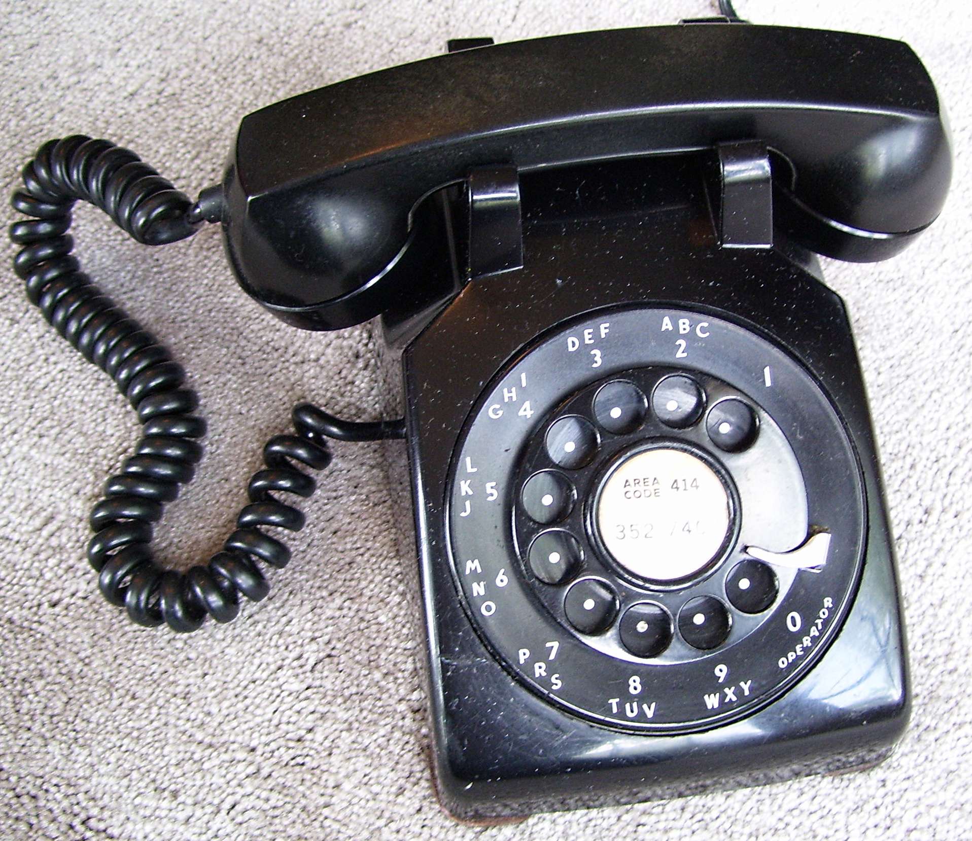
Pulse dialing is a signaling technology in telecommunications in which a direct current local loop circuit is interrupted according to a defined coding system for each signal transmitted, usually a digit. This lends the method the often used name loop disconnect dialing. In the most common variant of pulse dialing, decadic dialing, each of the ten Arabic numerals are encoded in a sequence of up to ten pulses. The most common version decodes the digits 1 through 9, as one to nine pulses, respectively, and the digit 0 as ten pulses. Historically, the most common device to produce such pulse trains is the rotary dial of the telephone, lending the technology another name, rotary dialing.

The pulse repetition rate was historically determined based on the response time needed for electromechanical switching systems to operate reliably. Most telephone systems used the nominal rate of ten pulses per second, but operator dialing within and between central offices often used pulse rates up to twenty per second.

Early automatic exchanges

[edit]

Automatic telephone exchange systems were developed in the late 19th and early 20th century. For identification, telephone subscribers were assigned a telephone number unique to each circuit. Various methods evolved to signal the desired destination telephone number for a telephone call directly dialed by the subscriber. An automatic switch-hook was designed by Hilborne Roosevelt.[1]

The first commercial automatic telephone exchange, designed by Almon Brown Strowger, opened in La Porte, Indiana on 3 November 1892, and used two telegraph-type keys on the telephone, which had to be operated the correct number of times to control the vertical and horizontal relay magnets in the exchange. But the use of separate keys with separate conductors to the exchange was not practical. The most common signaling system became a system of using direct-current pulse trains generated in the telephone sets of subscribers by interrupting the single-pair wire loop of the telephone circuit.

Rotary dial

[edit]

The first rotary dials worked by creating current interruptions on two separate direct current circuits (three-wire system) to actuate stepping motors in a vertical and horizontal (rotational) switch arrangement. Operating the dial error-free required smooth rotary motion of the finger wheel by the user, but was found as too unreliable. Later dials after c. 1907 produced just a single pulse train on a 2-wire circuit as the user rotated the dial to the finger stop starting at a different position for each digit transmitted. This mechanism was refined to include a recoil spring and a centrifugal governor to control the recoil speed. The user selected a digit to be dialed by inserting a finger into the corresponding hole and rotated the dial to the finger stop. When released from this position, the dial pulsing contacts were opened and closed repeatedly, thus interrupting the loop current in a pattern on the return to the home position. The exchange switch decoded the pattern for each digit thus transmitted by stepping relays or by accumulation in digit registers.

Pulse rate and coding

[edit]
Swedish phone with one pulse for 0

The mechanical nature of the stepping switches or relays employed at the switching system generally limited the speed of operation, the pulsing rate, to ten pulses per second.

The specifications of the Bell System in the US required service personnel to adjust dials in customer stations to a precision of 9.5 to 10.5 pulses per second (PPS), but the tolerance of the switching equipment was generally between 8 and 11 PPS.[2] The British (GPO, later Post Office Telecommunications) standard for Strowger switch exchanges has been ten impulses per second (allowable range 7 to 12) and a 66% break ratio (allowable range 63% to 72%).[3][4]

In most switching systems one pulse is used for the digit 1, two pulses for 2, and so on, with ten pulses for the digit 0; this makes the code unary, excepting the digit 0. Exceptions to this are Sweden, with one pulse for 0, two pulses for 1, and so on, and New Zealand, with ten pulses for 0, nine pulses for 1, etc. Oslo, the capital city of Norway, used the New Zealand system, but the rest of the country did not. Systems that used this encoding of the ten digits in a sequence of up to ten pulses are known as decadic dialing systems.

Some switching systems used digit registers that doubled the allowable pulse rate up to twenty pulses per second, and the inter-digital pause could be reduced as the switch selection did not have to be completed during the pause. These included access lines to the panel switch in the 1920s, crossbar systems, the later version (7A2) of the rotary system, and the earlier 1970s stored program control exchanges.

In some telephones, the pulses may be heard in the receiver as clicking sounds. However, in general, such effects were undesirable and telephone designers suppressed them with off-normal switches on the dial to exclude the receiver from the circuit, or greatly attenuated them by electrical means with a varistor connected across the receiver.

British (GPO) Type 232 telephone of 1932

Successors

[edit]

It was recognized as early as the 1910s that push buttons were faster than rotary dials, when the first panel switches used keys for dialing at the operator stations. In the 1940s, Bell Laboratories conducted field trials of pushbutton telephones for customer dialing to determine accuracy and efficiency. However, the technology of using mechanical reed relays was too unreliable until transistors transformed the industry. In 1963, the Bell System introduced to the public dual-tone multi-frequency (DTMF) technology under the name Touch-Tone, which was a trademark in the U.S. until 1984.[5] The Touch-Tone system used push-button telephones. In the decades after 1963, rotary dials were gradually phased out on new telephone models in favor of keypads and the primary dialing method to the central office became touchtone dialing. Most central office systems still support rotary telephones today. Some keypad telephones have a switch or configuration method for the selection of tone or pulse dialing.

Mobile telephones and most voice-over-IP systems use out-of-band signaling and do not send any digits until the entire number has been keyed by the user. Many VoIP systems are based on the Session Initiation Protocol (SIP), which uses a form of Uniform Resource Identifiers (URI) for addressing, instead of digits alone.

Switch-hook dialing

[edit]

As pulse dialing is achieved by interruption of the local loop, it was possible to dial digits by rapidly tapping, i.e. depressing, the switch hook the corresponding number of times at approximately ten taps per second.[6] However, many telephone makers implemented a slow switch hook release to prevent rapid switching.

In the United Kingdom, it was once possible to make calls from coin-box phones by tapping the switch hook without depositing coins. Unlawfully obtaining a free telephone call was deemed a criminal offence, abstracting electricity[7] from the General Post Office, which operated the telephone system, and several cases were prosecuted.

In popular culture, tapping was shown in the film Red Dragon when prisoner Hannibal Lecter dialed out on a telephone without dialing mechanism. The technique was also used by the character Phantom Phreak in the film Hackers.

References

[edit]
Revisions and contributorsEdit on WikipediaRead on Wikipedia
from Grokipedia
Pulse dialing is a telecommunications signaling system used in early automatic telephone exchanges to transmit dialed digits by interrupting the direct current on the subscriber's local loop, with the number of interruptions (pulses) corresponding to the digit selected—typically one pulse for digit 1 up to ten pulses for digit 0. This method, also known as decadic or loop-disconnect dialing, relies on electromechanical components to generate pulses at a standard rate of approximately 10 pulses per second, enabling the central office equipment to interpret and route calls without human operators. The technology originated in the late 19th century as part of the development of automatic telephone switching. In 1891, American inventor , an undertaker frustrated by operator-mediated calls, patented an automatic exchange system (U.S. Patent No. 447,918, granted in 1892) that incorporated a precursor to the for generation, allowing subscribers to directly signal numbers via mechanical interruptions. The first commercial Strowger exchange, supporting up to 99 lines, was installed in , in 1892, marking the practical introduction of and revolutionizing by reducing reliance on manual switchboards. By the early , became standard on telephones worldwide, with trains featuring a 60-67% break-to-make ratio (e.g., 66 ms break and 33 ms make per pulse) to ensure reliable detection by stepping relays in electromechanical switches. In operation, a rotary dial's finger plate is rotated to the desired digit, tensioning a spring; upon release, a pulse wheel with perforations passes between contacts, creating the interruptions while a regulates the return speed to maintain consistent timing, and an inter-digit pause of at least 420-700 ms allows the exchange to each digit. Later adaptations included push-button telephones that emulated pulse dialing electronically for compatibility with legacy systems. Pulse dialing dominated through the mid-20th century but began declining in the with the introduction of dual-tone multi-frequency (DTMF) signaling by the on November 18, 1963, which offered faster dialing, audible tones instead of clicks, and support for advanced features like automated menus. Despite its obsolescence in modern networks, pulse dialing remains supported in some rural or legacy plain old telephone service (POTS) lines for .

Historical Development

Invention in Early Automatic Exchanges

Pulse dialing originated with the invention of the by , an undertaker from , who developed the concept in 1889 to automate telephone call routing and eliminate operator intervention. Strowger patented his design in 1891 (U.S. 447,918), creating the first electromechanical that used electrical pulses to select and connect circuits without human assistance. The step-by-step switching mechanism operated by interpreting dial-generated pulses to advance electromagnetic wipers vertically through rows and rotationally across columns in a contact bank, corresponding directly to the digits of a number for precise call routing. Each digit's pulses stepped the switch incrementally, enabling the system to handle up to 99 lines initially through a 10x10 grid, with later enhancements expanding capacity. The rotary dial emerged as the primary for producing these interrupt pulses during digit selection. The first commercial installation of a Strowger-based automatic exchange occurred on November 3, 1892, in , serving 75 subscribers and marking the world's initial deployment of pulse-driven automated telephony. By the early , the technology expanded to larger cities, with practical installations in U.S. independent exchanges such as those in , and , supporting thousands of lines each. By 1914, over 400,000 pulse-dial telephones were in operation across the U.S., representing about 14% of all installations. Early systems faced significant challenges, including mechanical reliability due to the numerous moving parts in the stepping mechanisms, which were prone to wear and misalignment over time. Pulse synchronization also proved difficult, requiring precise timing from the dial to ensure accurate stepping without errors in large-scale deployments. These issues initially limited adoption to smaller exchanges, though iterative improvements enhanced durability and performance.

Adoption and Standardization

Following the invention of early automatic exchanges, pulse dialing saw rapid adoption within the Bell System in the United States starting after 1910, driven by the need to handle growing subscriber numbers and reduce reliance on manual operators. The first commercial panel switch installation occurred in Omaha, Nebraska, in December 1921, followed by Newark, New Jersey, in January 1922, marking the beginning of widespread urban deployment. By 1930, approximately 32% of Bell System telephones utilized dial technology, with full automation in major urban centers like Manhattan, where every connected telephone used panel switches. Internationally, spread to in the , with the United Kingdom's (GPO) playing a key role in implementation. Britain installed its first experimental automatic exchange in 1912, but significant rollout accelerated in the mid-, including the Epsom switch by the Automatic Telephone Manufacturing Company and the director system at in 1927. By March 1928, the proportion of automatic telephones in Britain exceeded the U.S. rate of 12.4%, and between 1920 and 1940, nearly 3,200 Strowger exchanges were deployed, reaching 56% of local exchanges by 1940. To ensure interoperability across borders, the International Consultative Committee for Telephones (CCIF) initiated standardization efforts for telephone signaling in the , including norms for international connections that facilitated pulse-based . Key milestones in the 1920s and 1930s included the refinement of pulse-based switching through and technologies. The , introduced by in 1915 and first commercially used in 1921, became the standard for urban exchanges due to its ability to handle direct control pulses for call routing. By the mid-1920s, high costs prompted development of the , patented in 1915 but first installed in in 1938, which improved reliability and reduced maintenance for pulse signaling in both local and long-distance networks. Regulatory initiatives during this period, including those by national postal authorities and international bodies like the CCIF, worked to harmonize signaling practices for seamless cross-network operation. The adoption of pulse dialing had significant socio-economic impacts, primarily by diminishing dependence on human operators and spurring growth in . In the U.S., mechanized over half the between 1920 and 1940, leading to a 50-80% reduction in operator employment in affected cities, with young women's participation in the role dropping from about 4% in 1930 to 1.3% by 1940. This shift freed resources for expanded services, enabling more efficient long-distance connections by minimizing local operator intervention, though it initially displaced entry-level jobs before reallocation into clerical and service sectors. In , similar reductions in operator needs supported network expansion, contributing to broader access in growing urban populations.

Operating Mechanism

Rotary Dial Design and Function

The , central to pulse dialing systems, features a circular disc approximately 7.5 cm in with ten finger holes arranged around its perimeter, each corresponding to a digit from 1 to 9 and 0. The numbering typically progresses from 1 to 9, followed by 0, with the 0 hole positioned just before the finger stop to facilitate a full for that digit. Early designs, dating to the late , used raised lugs instead of holes for finger placement, but by the , the modern hole-based configuration became standard in telephone exchanges. This layout allowed for alphanumeric labeling above the digits (excluding 1 and 0), aiding in party-line and systems. To dial a digit, the user inserts a finger into the corresponding hole and rotates the disc clockwise against spring tension until it reaches the fixed finger stop, a metal or barrier that limits travel and ensures consistent positioning. Upon release, the spring drives the disc back to its home position, while a —a set of weighted arms connected to a —regulates the return speed to approximately 10 pulses per second, preventing overly rapid or erratic motion that could cause dialing errors. This return motion generates a series of electrical interruptions in the loop circuit, with the number of interruptions matching the digit (1 for 1, up to 10 for 0). The process per digit typically takes 1 to 3 seconds, depending on the digit's position, as higher numbers require greater and thus longer return times. Design variations included adjustable finger stops to allow for customizable inter-digit pauses, reducing errors in multi-digit sequences, and anti-dialing safeguards such as the governor's speed control to avoid pulse miscounts from hasty operation. Early rotary dials, introduced around 1919 with automatics, were typically constructed from metal for the housing and disc. By the 1930s, —a durable, heat-resistant phenolic resin—was often used, providing insulation and rigidity suitable for . By the mid-20th century, materials evolved to lighter, cheaper thermoplastics like and ABS, improving with smoother surfaces and reduced weight while maintaining mechanical integrity. The assignment of 10 pulses to the digit 0 stemmed from historical conventions in telephone switching, where 0 was reserved for connecting to the operator's trunk lines in manual and early systems, necessitating a distinct, full-cycle signal to differentiate it from other digits. This ergonomic choice ensured reliable operator access without confusion, as the dial's design tied the longest rotation to the most critical function in pre-direct-dial eras.

Pulse Generation and Transmission

In pulse dialing systems, the acts as the primary , converting mechanical rotation into electrical signals through a series of interruptions in the telephone line's (DC) loop. When a user rotates the finger wheel to select a digit and releases it, a spring-driven mechanism causes a wheel or cam to engage with make-break contacts, repeatedly opening and closing the circuit during the dial's return to its rest position. This action creates on-off interruptions in the DC loop current, which is typically maintained at 20-50 mA by the central office battery across the two-wire . Each interruption corresponds to one , with the number of equaling the dialed digit (for example, dialing "5" produces five interruptions). The make-break contacts are the core components responsible for these interruptions, designed to handle the mechanical stress of rapid opening and closing without excessive wear. In some systems, a small is connected across these contacts to shape the pulses and suppress arcing, which can occur due to inductive effects in the line and lead to contact degradation or . This , often part of an RC quenching network, helps produce cleaner pulse edges by transient voltages during breaks. The resulting train represents the dialed information in a simple binary-like on-off keying format, where the "off" periods (breaks) dominate to ensure reliable detection. These electrical pulses are transmitted over the subscriber's twisted-pair —a standard unshielded two-conductor cable connecting the to the central office—where the varying loop current modulates the signal without requiring additional modulation. Upon reaching the central office, the pulses activate a line relay, an electromechanical device that responds to the interruptions by stepping or counting each to interpret the digit. The relay's operation ensures the pulses are regenerated and processed for call routing, maintaining over typical loop lengths up to several kilometers. To prevent errors such as overlapping digits, the dial's return speed is regulated by a built-in , which enforces a consistent rate and creates a mandatory inter-digit pause before the next digit can be dialed. This pause, typically longer than the pulse train duration, allows the central office equipment to reset and distinguish between successive digits clearly, avoiding miscounts from premature or blurred signaling.

Technical Specifications

Pulse Timing and Rates

In pulse dialing systems, the timing of electrical interruptions in the subscriber loop circuit is standardized to ensure reliable digit transmission and exchange response. The predominant rate in North American networks, as established by practices, is 10 pulses per second (pps), resulting in a 100 ms period per . Each comprises a break interval of approximately 60 ms, during which the loop is open to interrupt current flow, followed by a make interval of 40 ms, restoring the circuit. This 60:40 break-to-make ratio provides adequate time for electromechanical relays in the central office to detect and respond to the interruption without false triggering during the make phase. Regional variations adjust these parameters for compatibility with local equipment. In many European systems, a nominal 10 pps rate persists but with a break-to-make of approximately 63:37 (63 ms break, 37 make), though variations like 67:33 exist, optimizing for different relay characteristics. Some systems, particularly in , utilize a faster 20 pps rate, halving the pulse period to 50 ms while maintaining proportional break-make ratios, to accelerate dialing in high-speed environments. These rates ensure the pulses representing digits—ranging from 1 pulse for digit 1 to 10 pulses for digit 0—are distinguishable. Inter-digit pauses are equally vital, allowing the exchange relays to settle and count pulses accurately before the next digit begins. North American standards specify a minimum inter-digit interval of 600 ms, with 700 ms recommended to accommodate processing delays. Mechanical dials inherently provide longer pauses due to finger movement, but electronic implementations must enforce this timing. To mitigate inconsistencies from mechanical wear or manufacturing, specifications include tolerances of approximately ±5% on the overall rate (9.5 to 10.5 pps) and individual widths, as per practices. The break-make ratio allows deviations typically in the range of 63% to 72% break (about ±7% around nominal), depending on the system, to maintain clean operation. Longer subscriber lines can introduce , as line capacitance and resistance may elongate the effective make period or shorten the break due to slower discharge, potentially reducing recognition accuracy beyond tolerances on extended loops exceeding several kilometers. measurements focus on break duration and the break-make ratio, often verified using oscilloscopes or dial analyzers to confirm 60:40 proportions for optimal performance.

Signal Coding and Decoding

In pulse dialing systems, the coding scheme employs a where each digit corresponds to a precise number of electrical s transmitted over the local loop: one pulse for the digit 1, two pulses for 2, up to nine pulses for 9, and ten pulses for 0. This pulse train is generated by the interruptions in the circuit as the returns to its resting position, with the sequence of trains encoding the full number—typically seven digits for local calls within the (NANP). The decoding process in electromechanical telephone exchanges relies on line to detect and count these pulses, enabling the step-by-step progression of switching selectors. Upon off-hook detection and provision of , the line relay operates to seize a line finder, which connects the calling line to the first selector; subsequent pulses cause the relay to drop and re-operate, incrementing the selector's position for each interruption. In step-by-step () exchanges, this direct pulse counting drives the wiper arms of uniselectors and selectors without intermediate storage, with slow-release (such as relay C for vertical movement or relay E for rotary) timing the end of each digit after a brief pause, typically 200 milliseconds, to confirm the count and advance to the next stage. Multi-stage selection interprets the pulse sequences hierarchically across a series of selectors to route the call: the first and second selectors handle the thousands and hundreds digits to access office trunks, while the final connector selector processes the tens and units digits to select the called line from banks of up to 100 or 200 subscribers. This progressive decoding ensures efficient path establishment in large exchanges serving thousands of lines, with each stage's relay-counted steps aligning the wipers to the appropriate contact banks. Error handling in pulse decoding includes timeouts to manage incomplete or erratic dialing, such as requiring the first digit within 10 seconds of receipt and enforcing interdigit pauses of at least 600 milliseconds (up to 3 seconds maximum) to distinguish digit boundaries. If pulses exceed the selector's capacity (e.g., more than 10 for a 10-position ), the mechanism truncates to the final position, potentially leading to misrouting, while prolonged inactivity—such as no further digits after an initial sequence—triggers ringing on the partially selected line if available, or a total call timeout around 30 seconds to release resources. Some advanced systems provided audible confirmation tones after each digit to guide users, though this was less common in basic setups.

Switch-Hook Dialing

Switch-hook dialing, also known as hookswitch pulsing, is a pulse-based method for entering digits by manually operating the hook switch on telephones lacking a or keypad. The user generates pulses by rapidly pressing and releasing the hook switch, which interrupts the loop on the the number of times equal to the desired digit; for instance, ten quick interruptions signal the digit 0. This technique mimics the pulse generation of s but relies on human-controlled timing rather than mechanical automation. The mechanism functions by creating brief open-circuit interruptions in the line current, detectable by the central office equipment as square-wave s. Each typically consists of a 45-millisecond on-hook depression followed by a 55-millisecond off-hook release, yielding a standard rate of about 10 s per second to ensure compatibility with exchanges. An inter-digit pause of approximately 700 milliseconds is required to separate digits, making the process slower than automated methods; dialing a single 0, for example, requires about 1.7 seconds excluding the pause. These s are counted by the switch in the same manner as outputs, allowing seamless integration with existing pulse-based systems. Historically, switch-hook dialing originated in the manual switchboard era of the late 19th and early 20th centuries, where operators used hook flashes for signaling, and was later adapted for subscriber use in automatic networks. It gained prominence in environments requiring simple, dial-less telephones, such as early payphones that relied on coin insertion for access but used hook pulsing for number entry in some designs, and military field phones during . In the U.S. military, portable field telephones like the EE-8 model, employed extensively in WWII, supported hook-switch pulsing when connected to pulse-compatible exchanges, enabling soldiers to interface with automated networks without specialized dialing hardware. This adaptation was particularly useful in forward areas where rugged, minimalistic equipment was essential. The primary advantage of switch-hook dialing lies in its hardware simplicity, as it eliminates the need for a dedicated dial mechanism, reducing costs and improving reliability in harsh conditions like use. However, it is inherently slower and more error-prone due to the manual nature of generation, with users needing precise timing to avoid miscounts by the exchange; rates typically aimed for 5-10 s per second, but variations could lead to failed connections. Despite these drawbacks, its compatibility with standard rotary infrastructure ensured its viability until the widespread adoption of tone dialing in the mid-20th century.

Pulse Variations Across Systems

Pulse dialing systems exhibited significant variations across different countries and regions, primarily in pulse rates and coding schemes to accommodate local network designs and equipment capabilities. Most systems used a standard rate of 10 pulses per second (pps) for subscriber dialing, which became the benchmark for networks worldwide and allowed for reliable over typical local loops. However, operator dialing within and between central offices often used faster pulse rates up to 20 pps to enable quicker signaling. Coding variations also existed; for example, used a reversed scheme where digit 0 was represented by 1 pulse and 9 by 10 pulses, while employed a more complex system with additional coding for certain digits. During the transition to modern in the 1970s, hybrid solutions like pulse-to-tone converters emerged to bridge legacy pulse systems with emerging tone-based networks, automatically translating dial pulses into dual-tone multi-frequency (DTMF) signals for compatibility in mixed infrastructures. These devices facilitated gradual upgrades without immediate replacement of all equipment, preserving functionality in areas with uneven adoption of touch-tone technology.

Decline and Modern Context

Transition to Tone Dialing

The transition from pulse dialing to dual-tone multi-frequency (DTMF) signaling began in the mid-20th century as telephone networks evolved toward electronic systems. In 1963, the Bell System introduced the first commercial DTMF-capable telephone, the Western Electric model 1500 Princess phone, in Pennsylvania on November 18. This push-button device marked a shift from mechanical rotary dials, using pairs of audio tones in the voice-frequency band to represent digits, which switching centers could decode more efficiently. DTMF offered key advantages over pulse dialing, particularly in speed and reliability. Each digit in DTMF is transmitted via tones lasting at least 50 milliseconds, with an interdigit interval of at least 45 milliseconds, enabling a full seven-digit number to be dialed much faster than pulse dialing's 10 pulses per second rate, where the digit 9 required nearly a second of interruptions alone. This efficiency reduced call setup times, increased trunk capacity, and facilitated integration with emerging computerized interfaces, as tones were simpler for electronic detectors to process than mechanical pulse relays. The No. 1 Electronic Switching System (1ESS), deployed by Bell in , exemplified this preference, using stored-program control and reed relays that handled DTMF tones more readily for advanced features like . Adoption timelines varied globally due to differences. In the , DTMF spread gradually from , becoming widespread by the as manufacturers standardized sets and the optional monthly surcharge was phased out, aligning with the growth of electronic exchanges. Internationally, rollout was slower; in , state-owned telecom monopolies delayed implementation until the 1970s and , citing high costs to upgrade existing pulse-based . To ensure backward compatibility during the shift, telephone exchanges employed converters: early DTMF signals were translated to pulse equivalents in central offices serving legacy mechanical switches, while later digital systems added pulse-to-tone converters to support rotary phones. This dual-support persisted into the 2000s, allowing rotary devices to function on modern networks until many providers optimized for tones alone.

Legacy and Current Applications

Despite the widespread transition to tone dialing, pulse dialing maintains compatibility with certain legacy Plain Old Telephone Service (POTS) lines, particularly in rural areas where analog infrastructure persists amid ongoing network sunsets. As of 2025, these systems still support pulse signals for basic voice calls, allowing rotary phones to function without modification in regions delaying full digital upgrades. For integration with modern Voice over Internet Protocol (VoIP) services, specialized adapters convert pulse dialing signals to dual-tone multi-frequency (DTMF) tones, enabling vintage rotary phones to operate on digital networks. Devices such as the DialGizmo converter and those offered by Oldphoneworks facilitate this by detecting and translating the intermittent pulses generated by rotary dials into compatible tones for VoIP adapters like Grandstream models. Preservation efforts sustain pulse dialing through collector communities and institutional exhibits, where functional rotary systems are restored and demonstrated. Enthusiasts donate and maintain artifacts, contributing to collections at specialized venues like the JKL Museum of Telephony, which features working phones connected to historic Step-by-Step switches for interactive dialing experiences. Similarly, the International Airport's SFO hosts a retrospective exhibition of rotary telephones from the 1930s onward, loaned from archives to educate visitors on pulse-based signaling. The preserves design-line rotary models as part of its collection, highlighting their aesthetic and technical evolution. Other sites, including the Comporium Telephone and the Telephone in , offer hands-on displays of pulse dialing equipment to illustrate early automated switching. In contemporary applications, pulse-like signaling echoes in hobbyist and technical setups, such as Arduino-based controllers using rotary dials to generate precise pulse sequences for device automation in or (IoT) projects. These implementations repurpose the mechanical pulse mechanism for timing signals in low-power environments, demonstrating the technique's enduring simplicity. Culturally, pulse dialing evokes in media, with rotary phones frequently featured in and to depict mid-20th-century settings, symbolizing a slower-paced era in genres like horror where the deliberate dialing rhythm heightens tension.

References

Add your contribution
Related Hubs
User Avatar
No comments yet.