
Community hub
Recent from talks
Contribute something
Nothing was collected or created yet.
Skywave
View on Wikipedia
In radio communication, skywave or skip refers to the propagation of radio waves reflected or refracted back toward Earth from the ionosphere, an electrically charged layer of the upper atmosphere. Since it is not limited by the curvature of the Earth, skywave propagation can be used to communicate beyond the horizon, at intercontinental distances. It is mostly used in the shortwave frequency bands.
As a result of skywave propagation, a signal from a distant AM broadcasting station, a shortwave station, or – during sporadic E propagation conditions (principally during the summer months in both hemispheres) – a distant VHF FM or TV station can sometimes be received as clearly as local stations. Most long-distance shortwave (high frequency) radio communication – between 3 and 30 MHz – is a result of skywave propagation. Since the early 1920s amateur radio operators (or "hams"), limited to lower transmitter power than broadcast stations, have taken advantage of skywave for long-distance (or "DX") communication.
Skywave propagation is distinct from line-of-sight propagation, in which radio waves travel in a straight line, and from non-line-of-sight propagation.
Local and distant skywave propagation
[edit]Skywave transmissions can be used for long-distance communications (DX) by waves directed at a low angle as well as relatively local communications via nearly vertically directed waves (near vertical incidence skywaves – NVIS).
Low-angle skywaves
[edit]
The ionosphere is a region of the upper atmosphere, from about 80 km (50 miles) to 1000 km (600 miles) in altitude, where neutral air is ionized by solar photons, solar particles, and cosmic rays. When high-frequency signals enter the ionosphere at a low angle they are bent back towards the Earth by the ionized layer.[1] If the peak ionization is strong enough for the chosen frequency, a wave will exit the bottom of the layer earthwards – as if obliquely reflected from a mirror. Earth's surface (ground or water) then reflects the descending wave back up again towards the ionosphere.
When operating at frequencies just below the maximum usable frequency, losses can be quite small, so the radio signal may effectively "bounce" or "skip" between the Earth and ionosphere two or more times (multi-hop propagation), even following the curvature of the Earth. Consequently, even signals of only a few Watts can sometimes be received many thousands of miles away. This is what enables shortwave broadcasts to travel all over the world. If the ionization is not great enough, the wave only curves slightly downwards, and subsequently upwards as the ionization peak is passed so that it exits the top of the layer only slightly displaced. The wave is then lost in space. To prevent this, a lower frequency must be chosen. With a single "hop", path distances up to 3500 km (2200 miles) may be reached. Longer transmissions can occur with two or more hops.[2]
Near-vertical skywaves
[edit]Skywaves directed almost vertically are referred to as near-vertical-incidence skywaves (NVIS). At some frequencies, generally in the lower shortwave region, the high angle skywaves will be reflected directly back towards the ground. When the wave returns to ground it is spread out over a wide area, allowing communications within several hundred miles of the transmitting antenna. NVIS enables local plus regional communications, even from low-lying valleys, to a large area, for example, an entire state or small country. Coverage of a similar area via a line-of-sight VHF transmitter would require a very high mountaintop location. NVIS is thus useful for statewide networks, such as those needed for emergency communications.[3] In short wave broadcasting, NVIS is very useful for regional broadcasts that are targeted to an area that extends out from the transmitter location to a few hundred miles, such as would be the case in a country or language group to be reached from within the borders of that country. This will be much more economical than using multiple FM (VHF) or AM broadcast transmitters. Suitable antennas are designed to produce a strong lobe at high angles. When short range skywave is undesirable, as when an AM broadcaster wishes to avoid interference between the ground wave and sky wave, anti-fading antennas are used to suppress the waves being propagated at the higher angles.
Intermediate distance coverage
[edit]
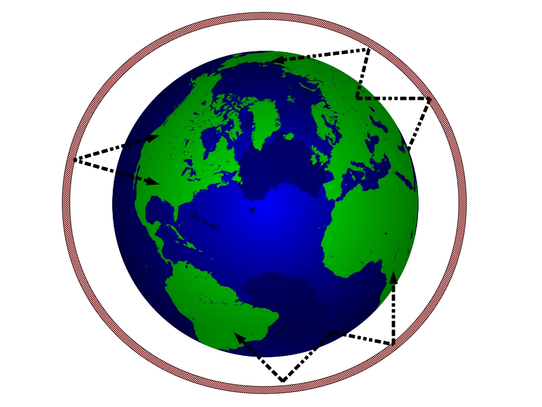
For every distance, from local to maximum distance transmission, (DX), there is an optimum "take off" angle for the antenna, as shown here. For example, to best reach a receiver 500 miles away during the night using the F layer, an antenna should be chosen that has a strong lobe at 40 degrees elevation. For the longest distances a lobe at low angles (below 10 degrees) is best. For NVIS, angles above 45 degrees are optimum. Suitable antennas for long distance would be a high Yagi or a rhombic; for NVIS, a dipole or array of dipoles about .2 wavelengths above ground; and for intermediate distances, a dipole or Yagi at about .5 wavelengths above ground. Vertical patterns for each type of antenna are used to select the proper antenna.
Fading
[edit]At any distance sky waves will fade. The layer of ionospheric plasma with sufficient ionization (the reflective surface) is not fixed, but undulates like the surface of the ocean. Varying reflection efficiency from this changing surface can cause the reflected signal strength to change, causing "fading" in shortwave broadcasts. Even more serious fading can occur when signals arrive via two or more paths, for example when both single-hop and double-hop waves interfere with other, or when a skywave signal and a ground-wave signal arrive at about the same strength. This is the most common source of fading with nighttime AM broadcast signals. Fading is always present with sky wave signals, and except for digital signals such as Digital Radio Mondiale seriously limit the fidelity of shortwave broadcasts.
Other considerations
[edit]VHF signals with frequencies above about 30 MHz usually penetrate the ionosphere and are not returned to the Earth's surface. E-skip is a notable exception, where VHF signals including FM broadcast and VHF TV signals are frequently reflected to the Earth during late spring and early summer. E-skip rarely affects UHF frequencies, except for very rare occurrences below 500 MHz.
Frequencies below approximately 10 MHz (wavelengths longer than 30 meters), including broadcasts in the mediumwave and shortwave bands (and to some extent longwave), propagate most efficiently by skywave at night. Frequencies above 10 MHz (wavelengths shorter than 30 meters) typically propagate most efficiently during the day. Frequencies lower than 3 kHz have a wavelength longer than the distance between the Earth and the ionosphere. The maximum usable frequency for skywave propagation is strongly influenced by sunspot number.
Skywave propagation is usually degraded – sometimes seriously – during geomagnetic storms. Skywave propagation on the sunlit side of the Earth can be entirely disrupted during sudden ionospheric disturbances.
Because the lower-altitude layers (the E-layer in particular) of the ionosphere largely disappear at night, the refractive layer of the ionosphere is much higher above the surface of the Earth at night. This leads to an increase in the "skip" or "hop" distance of the skywave at night.
History of discovery
[edit]Amateur radio operators are credited with the discovery of skywave propagation on the shortwave bands. Early long-distance services used ground wave propagation at very low frequencies,[4] which are attenuated along the path. Longer distances and higher frequencies using this method meant more signal attenuation. This, and the difficulties of generating and detecting higher frequencies, made discovery of shortwave propagation difficult for commercial services.
Radio amateurs conducted the first successful transatlantic tests using waves shorter than those used by commercial services[5] in December 1921, operating in the 200 meter mediumwave band (1500 kHz)—the shortest wavelength then available to amateurs. In 1922 hundreds of North American amateurs were heard in Europe at 200 meters and at least 30 North American amateurs heard amateur signals from Europe. The first two-way communications between North American and Hawaiian amateurs began in 1922 at 200 meters.
Extreme interference at the upper edge of the 150-200 meter band—the official wavelengths allocated to amateurs by the Second National Radio Conference[6] in 1923—forced amateurs to shift to shorter and shorter wavelengths; however, amateurs were limited by regulation to wavelengths longer than 150 meters (2 MHz). A few fortunate amateurs who obtained special permission for experimental communications below 150 meters completed hundreds of long-distance two-way contacts on 100 meters (3 MHz) in 1923 including the first transatlantic two-way contacts[7] in November 1923, on 110 meters (2.72 MHz)
By 1924 many additional specially licensed amateurs were routinely making transoceanic contacts at distances of 6000 miles (~9600 km) and more. On 21 September several amateurs in California completed two way contacts with an amateur in New Zealand. On 19 October amateurs in New Zealand and England completed a 90-minute two-way contact nearly halfway around the world. On October 10, the Third National Radio Conference made three shortwave bands available to U.S. amateurs[8] at 80 meters (3.75 MHz), 40 meters (7 MHz) and 20 meters (14 MHz). These were allocated worldwide, while the 10-meter band (28 MHz) was created by the Washington International Radiotelegraph Conference[9] on 25 November 1927. The 15-meter band (21 MHz) was opened to amateurs in the United States on 1 May 1952.
Marconi
[edit]Guglielmo Marconi was the first to show that radios could communicate beyond line-of-sight, using the reflective properties of the ionosphere. On December 12, 1901, he sent a message around 2,200 miles (3,500 km) from his transmission station in Cornwall, England, to St. John's, Newfoundland (now part of Canada). However, Marconi believed the radio waves were following the curvature of the Earth – the reflective properties of the ionosphere that enables 'sky waves' were not yet understood. Skepticism from the scientific community and his wired telegraph competitors drove Marconi to continue experimenting with wireless transmissions and associated business ventures over the next few decades.[10]
In June and July 1923, Guglielmo Marconi's land-to-ship transmissions were completed during nights on 97 meters from Poldhu Wireless Station, Cornwall, to his yacht Ellette in the Cape Verde Islands. In September 1924, Marconi transmitted during daytime and nighttime on 32 meters from Poldhu to his yacht in Beirut. Marconi, in July 1924, entered into contracts with the British General Post Office (GPO) to install high speed shortwave telegraphy circuits from London to Australia, India, South Africa and Canada as the main element of the Imperial Wireless Chain. The UK-to-Canada shortwave "Beam Wireless Service" went into commercial operation on 25 October 1926. Beam Wireless Services from the UK to Australia, South Africa and India went into service in 1927.
Far more spectrum is available for long-distance communication in the shortwave bands than in the long wave bands; and shortwave transmitters, receivers and antennas were orders of magnitude less expensive than the multi-hundred kilowatt transmitters and monstrous antennas needed for long wave.
Shortwave communications began to grow rapidly in the 1920s,[11] similar to the internet in the late 20th century. By 1928, more than half of long-distance communications had moved from transoceanic cables and long-wave wireless services to shortwave "skip" transmission, and the overall volume of transoceanic shortwave communications had vastly increased. Shortwave also ended the need for multimillion-dollar investments in new transoceanic telegraph cables and massive long-wave wireless stations, although some existing transoceanic telegraph cables and commercial long-wave communications stations remained in use until the 1960s.
The cable companies began to lose large sums of money in 1927, and a serious financial crisis threatened the viability of cable companies that were vital to strategic British interests. The British government convened the Imperial Wireless and Cable Conference[12] in 1928 "to examine the situation that had arisen as a result of the competition of Beam Wireless with the Cable Services". It recommended and received Government approval for all overseas cable and wireless resources of the Empire to be merged into one system controlled by a newly formed company in 1929, Imperial and International Communications Ltd. The name of the company was changed to Cable and Wireless Ltd. in 1934.
See also
[edit]- Radio propagation
- MW DX
- TV-FM DX
- Near-Vertical Incidence Skywave (NVIS)
- F-layer
- Over-the-horizon radar
- Groundwave
- Schumann resonances
- Kennelly–Heaviside layer
- Skip zone
- Project West Ford
- Radio frequency
- Clear-channel station
- Utility station
- Tropospheric ducting
- Geomagnetic storm
- History of radio
- Amateur radio history
- List of electronics topics
References
[edit]- ^ Wave Handbook. Sony Corporation. 1998. p. 14. OCLC 734041509.
- ^ Rawer, K. (1993). Wave Propagation in the Ionosphere. Dordrecht: Kluwer Academic Publications. ISBN 0-7923-0775-5.
- ^ Silver, H.L., ed. (2011). The ARRL Handbook for Radio Communications (88th ed.). Newington, CT: American Radio Relay League.
- ^ Stormfax. Marconi Wireless on Cape Cod
- ^ "1921 - Club Station 1BCG and the Transatlantic Tests". Radio Club of America. Retrieved 2009-09-05.
- ^ "Radio Service Bulletin No. 72". Bureau of Navigation, Department of Commerce. 1923-04-02. pp. 9–13. Retrieved 2018-03-05.
{{cite magazine}}: Cite magazine requires|magazine=(help) - ^ [1] Archived November 30, 2009, at the Wayback Machine
- ^ "Frequency or wave band allocations", Recommendations for Regulation of Radio Adopted by the Third National Radio Conference (October 6–10, 1924), page 15.
- ^ "Report". twiar.org.
- ^ Marconi Archived 2022-11-21 at the Wayback Machine
- ^ Full text of "Beyond the ionosphere : fifty years of satellite communication". 1997. ISBN 9780160490545. Retrieved 2012-08-31.
- ^ Cable and Wireless Pl c History Archived 2015-03-20 at the Wayback Machine
Further reading
[edit]- Davies, Kenneth (1990). Ionospheric Radio. IEE Electromagnetic Waves Series #31. London, UK: Peter Peregrinus Ltd/The Institution of Electrical Engineers. ISBN 978-0-86341-186-1.
External links
[edit]- Navy - Propagation of Waves
- Radio wave propagation basics
- HFRadio Propagation forums
- Rare gamma-ray flare disturbed ionosphere Archived 2017-07-06 at the Wayback Machine
- Articles on sporadic E and 50 MHz Radio Propagation
- Radio propagation overview Details of many forms of radio propagation
Skywave
View on GrokipediaFundamentals of Skywave Propagation
Definition and Principles
Skywave propagation is a mode of radio wave transmission in which electromagnetic waves are reflected, refracted, or scattered by the ionosphere, allowing communication beyond the line-of-sight horizon.[5] This mechanism primarily operates in the high-frequency (HF) band, spanning 3 to 30 MHz, where waves can interact effectively with ionized atmospheric layers to achieve long-distance coverage.[5] Unlike ground wave propagation, which follows the Earth's surface through diffraction and is limited to lower frequencies and shorter ranges, or space wave propagation, which relies on direct line-of-sight paths and is confined to very high frequencies (VHF) and above, skywave enables global reach by leveraging ionospheric effects.[6] The foundational principles of skywave propagation stem from the behavior of electromagnetic waves in the ionized atmosphere, where free electrons alter the medium's properties. Electromagnetic waves propagate as transverse oscillations of electric and magnetic fields, but in the ionosphere, ionization introduces a plasma-like environment that modifies wave speed and direction. The refractive index , which dictates how waves bend, decreases below unity due to electron density , following the approximate relation , where is the wave frequency in Hz and is in electrons per cubic meter; this change arises because the plasma frequency interacts with the incident wave, slowing it in regions of higher ionization.[5] Wave polarization plays a critical role, as the Earth's magnetic field splits waves into ordinary (unaffected by the field) and extraordinary (rotated by it) modes, influencing absorption and reflection efficiency.[6] The angle of incidence, defined relative to the normal of the ionospheric boundary, determines whether the wave refracts, reflects, or penetrates, with shallower angles favoring longer propagation paths.[6] A key principle governing ionospheric refraction is Snell's law, which describes the bending of waves at interfaces of differing refractive indices and extends to the gradual curvature in continuously varying media like the ionosphere. The law states , where and are the refractive indices of the two media, and and are the angles of incidence and refraction, respectively, measured from the normal.[6] This equation derives from the continuity of wave phase across the boundary, ensuring the wavefronts match in speed and direction; specifically, it follows from Fermat's principle of least time, where the path minimizes travel time, or from the wave equation solution imposing boundary conditions on the tangential wave vector component , which remains constant across the interface (with as the speed of light).[6] In the ionosphere, where decreases with height due to rising , Snell's law implies progressive bending toward the normal as decreases to maintain the invariant ; if , total internal reflection occurs when , defining the critical angle , beyond which waves reflect back to Earth instead of penetrating.[6] For skywave, this bending or reflection enables the wave to return to the surface after interacting with the ionosphere as the medium.[5]Ionospheric Reflection Mechanism
The ionosphere consists of several distinct layers defined by altitude ranges and electron density profiles, which vary with solar illumination and play key roles in radio wave interactions. The D layer, situated at altitudes of 60–90 km, forms primarily during daytime with relatively low electron densities on the order of 10^9 to 10^{10} electrons per cubic meter, resulting in a profile that peaks near 70 km before decreasing; it acts as an absorbing region for low-frequency radio waves due to frequent electron-neutral collisions.[7] The E layer occupies 90–150 km, featuring moderate electron densities up to about 10^{11} electrons per cubic meter with a peak around 110 km, and it occasionally experiences sporadic E enhancements—thin, high-density patches that can reflect frequencies up to 100 MHz.[8] The F1 layer, present only during daytime at 150–250 km, exhibits higher electron densities peaking at approximately 10^{11} to 10^{12} electrons per cubic meter near 200 km in a smooth profile shaped by photoionization; the F2 layer, the uppermost and most critical for skywave propagation, spans 250–500 km with the highest electron densities, often exceeding 10^{12} electrons per cubic meter at its peak around 300–400 km, forming a broad profile that enables reflection of high-frequency signals.[7][9] The primary mechanism for skywave reflection arises from the ionosphere's plasma properties, where free electrons interact with electromagnetic waves. The plasma angular frequency is given by where is the electron density, is the elementary charge, is the permittivity of free space, and is the electron mass; radio waves with angular frequency less than encounter a region where the dielectric constant becomes negative, leading to total reflection at the altitude where , while waves with can penetrate deeper.[10] In practice, this reflection occurs most effectively in the F2 layer due to its high , supporting skywave propagation for frequencies typically below 30 MHz.[11] Rather than sharp reflection at a boundary, the ionosphere's gradual electron density gradient causes ray bending through refraction, effectively turning waves back toward Earth. This behavior is described by magneto-ionic theory via the Appleton-Hartree equation, which provides the complex refractive index for wave propagation in a magnetized, collisional plasma: where represents the ratio of plasma to wave frequency squared, and accounts for collisions with neutral frequency ; as increases with altitude, rises, reducing progressively until the ray path curves sufficiently to return, mimicking reflection, while absorption is incorporated through the imaginary component influenced by .[12] In the absence of collisions (), the equation simplifies to , highlighting pure refractive bending.[13] Day-night variations in layer heights and densities stem from solar ultraviolet (UV) radiation, which drives photoionization during daylight. Daytime EUV and X-ray fluxes ionize neutral atoms, elevating electron densities across layers—particularly boosting the F region's peak by factors of 10 to 100—while raising layer altitudes slightly due to thermal expansion; at night, without solar UV, rapid recombination reduces densities, causing the D layer to dissipate entirely within hours, the E layer to weaken significantly, and the F1 layer to merge with F2 into a single, lower-density F layer at reduced heights around 250–350 km.[7][14] These diurnal changes alter reflection capabilities, with stronger daytime absorption in D but enhanced propagation via F layers.[15]Types of Skywave Propagation
Low-Angle Skywaves
Low-angle skywaves involve the propagation of high-frequency (HF) radio signals launched from antennas at radiation angles less than 20° above the horizontal, facilitating single-hop distances typically ranging from 2000 to 4000 km through reflection off the F-layer of the ionosphere.[16][17] This configuration contrasts with higher-angle launches by prioritizing extended ground range over vertical penetration, making it suitable for transcontinental communications where the ionospheric reflection occurs at shallow grazing angles.[18] The geometry of low-angle skywave paths can be described through ray tracing, where the signal departs the transmitter at a low elevation angle, travels obliquely upward to intersect the F-layer (typically at 200-400 km altitude) at an incidence angle approaching 90° from the vertical normal, undergoes refraction and reflection due to the plasma's refractive index gradient, and returns to Earth in a symmetric arc, covering the total hop distance along a near-great-circle route.[19] These paths often align with incidence conditions near the pseudo-Brewster angle in the ionosphere, where the ordinary magneto-ionic mode experiences minimal absorption, enhancing signal efficiency for horizontally polarized waves.[20] For visualization, the trajectory forms an elongated ellipse with foci at the transmitter and receiver, with the ionospheric apex offset laterally by roughly half the ground distance. This mode offers key advantages for long-distance (DX) communication, as the low launch angles maximize the horizontal component of propagation, enabling reliable coverage over vast oceans or continents without intermediate relays, while higher operating frequencies (above 10 MHz) reduce absorption in the lower D-layer, which is more pronounced for lower bands due to its inverse frequency-squared dependence.[21] A representative example is transatlantic HF links between North America and Europe, spanning approximately 3000-5000 km, commonly achieved via single- or dual-hop paths on the 15-meter (21 MHz) and 20-meter (14 MHz) amateur bands during favorable ionospheric conditions, where low-angle radiation from directional antennas like Yagis optimizes signal strength.[18]Near-Vertical Incidence Skywaves
Near-vertical incidence skywaves (NVIS) refer to a mode of high-frequency (HF) radio propagation where signals are launched at elevation angles greater than 60° from the horizontal, typically reflecting off the lower ionospheric layers such as the E or F1 regions to provide regional coverage within a radius of approximately 0-550 km, depending on frequency and ionospheric conditions.[22][23][24] This technique effectively fills the skip zones that occur in standard skywave propagation, enabling reliable short-range communications without the limitations of ground-wave signals over irregular terrain; ranges vary with ionospheric conditions, typically shorter during daytime due to D-layer absorption. The high launch angles, often exceeding 75-80°, result in near-perpendicular incidence on the ionosphere, promoting total internal reflection due to the refractive index gradient in the ionized layers.[22][23][25] The propagation mechanism relies on the ionosphere's ability to refract or reflect these high-angle signals back to Earth in an omnidirectional pattern, with reduced path loss compared to ground waves, particularly over rough or obstructed landscapes where surface wave attenuation is high. For instance, at frequencies around 5 MHz, the combined effects of spherical spreading and ionospheric absorption yield path losses of about -100 dB over 500 km, but the near-vertical path minimizes multi-hop complications and ground absorption losses inherent in longer oblique paths. This results in more stable signals for distances up to 300 miles (approximately 480 km), making NVIS suitable for single-hop operations.[23][26] Antenna configurations for NVIS emphasize horizontal polarization and low heights to maximize high-angle radiation. A resonant half-wavelength horizontal dipole elevated 0.1 to 0.25 wavelengths above ground—such as 10-20 feet at 7 MHz—produces an optimal elevation pattern with a beam width of about 100°, centered near vertical, achieving low voltage standing wave ratios (VSWR <3:1) for efficient power transfer. Higher elevations reduce the high-angle component, while excessively low heights increase ground losses, so the 0.15λ height is often ideal for broad coverage.[25] NVIS is widely employed in military tactical networks and emergency communications for area coverage, where line-of-sight VHF/UHF links fail due to terrain or foliage. In military contexts, it supports small-unit operations beyond ground-wave range, using frequencies in the 2-12 MHz band, with 4-7 MHz commonly selected for daytime reliability to avoid D-layer absorption while staying below the critical frequency for reflection. For example, the U.S. Marine Corps utilizes NVIS for continuous HF links up to 300 miles in obstructed environments, enhancing command and control during operations.[26][27]Multihop and Intermediate Coverage
Multihop propagation extends skywave communication ranges far beyond single-hop limits by involving multiple reflections of radio waves between the ionosphere and the Earth's surface, typically 2 to 5 hops for paths exceeding 10,000 km. Each hop via the F2 layer covers approximately 3,000 to 4,000 km, depending on the launch angle and ionospheric conditions, with the total distance accumulating as the signal bounces progressively farther. This mode is essential for long-distance HF communications, where signals reflect off the ionosphere (primarily the F2 region at night or during high solar activity) and then the ground before the next ionospheric encounter. Losses accumulate with each hop due to ground reflections and ionospheric absorption, particularly in the D region during descent.[28][5] A common example is the 3-hop path used in global shortwave broadcasting, where transmitters in Europe or North America reach audiences in Asia or Oceania over 10,000 km by leveraging successive F2 reflections, often optimized for frequencies around 5-15 MHz during nighttime hours. In such paths, the first hop might span 3,500 km, the second similar, and the third adjusting for the remaining distance, with overall signal strength reduced by 10-20 dB per additional hop compared to single-hop. Multihop paths are modeled using up to 6 F2 modes or 3 E modes for distances up to 7,000 km in standard predictions, beyond which trans-equatorial effects may dominate.[28][5][29] For intermediate distances of 800-2,000 km, where single-hop skywave may be unreliable due to skip zones, hybrid modes provide reliable coverage. The T-hop combines skywave reflection with ground wave propagation, allowing the signal to follow the Earth's surface for the initial segment before an ionospheric bounce fills the gap, effective over mixed terrain at MF/HF bands. Alternatively, the chordal hop utilizes oblique low-angle incidence to the ionosphere followed by a single ground reflection, but under tilted ionospheric conditions near sunrise, sunset, or the equator, it can achieve ionosphere-to-ionosphere propagation without ground contact, reducing reflection losses. These modes bridge short-range ground wave limits (under 500 km) and long-range pure skywave, often requiring antenna elevation angles of 10-20 degrees for optimal coupling.[5][28] Path loss in multihop and intermediate skywave propagation comprises free-space loss, ionospheric absorption, and hop-specific attenuations, significantly impacting signal strength. The free-space component is given by the formulawhere is the loss in dB, is the total path distance in km, and is the frequency in MHz; for multihop paths, this is calculated per hop and summed, with additional adjustments of about 2 dB per ground reflection (lower over seawater) and 5-15 dB for D-region absorption per upward leg. In intermediate T-hop or chordal paths, total loss might range 100-140 dB for 1,500 km at 10 MHz, emphasizing the need for high transmitter power (e.g., 10-50 kW) to maintain usable field strengths above 40 dBμV/m. These calculations are refined in models accounting for focusing gains or deviations near the maximum usable frequency.[28]