

Community hub
Recent from talks
Contribute something
Nothing was collected or created yet.
Petroleum reservoir
View on Wikipedia
A petroleum reservoir or oil and gas reservoir is a subsurface accumulation of hydrocarbons contained in porous or fractured rock formations. Such reservoirs form when kerogen (ancient plant matter) is created in surrounding rock by the presence of high heat and pressure in the Earth's crust.
Reservoirs are broadly classified as conventional and unconventional reservoirs. In conventional reservoirs, the naturally occurring hydrocarbons, such as crude oil (petroleum) or natural gas, are trapped by overlying rock formations with lower permeability, while in unconventional reservoirs the rocks have high porosity and low permeability, which keeps the hydrocarbons trapped in place, therefore not requiring a cap rock. Reservoirs are found using hydrocarbon exploration methods.
Oil field
[edit]

An oil field is an area of accumulated liquid petroleum underground in multiple (potentially linked) reservoirs, trapped as it rises to impermeable rock formations. In industrial terms, an oil field implies that there is an economic benefit worthy of commercial attention.[1][2] Oil fields may extend up to several hundred kilometers across the surface, meaning that extraction efforts can be large and spread out across the area. In addition to extraction equipment, there may be exploratory wells probing the edges to find more reservoir area, pipelines to transport the oil elsewhere, and support facilities.
Oil fields can occur anywhere that the geology of the underlying rock allows, meaning that certain fields can be far away from civilization, including at sea. Creating an operation at an oil field can be a logistically complex undertaking, as it involves the equipment associated with extraction and transportation, as well as infrastructure such as roads and housing for workers. This infrastructure has to be designed with the lifespan of the oil field in mind, as production can last many years. Several companies, such as Hill International, Bechtel, Esso, Weatherford International, Schlumberger, Baker Hughes and Halliburton, have organizations that specialize in the large-scale construction of the infrastructure to support oil field exploitation.
The term "oilfield" can be used as a shorthand to refer to the entire petroleum industry. However, it is more accurate to divide the oil industry into three sectors: upstream (crude oil production from wells and separation of water from oil), midstream (pipeline and tanker transport of crude oil) and downstream (refining of crude oil to products, marketing of refined products, and transportation to oil stations).
More than 65,000 oil fields are scattered around the globe, on land and offshore.[3] The largest are the Ghawar Field in Saudi Arabia and the Burgan Field in Kuwait, with more than 66 to 104 billion barrels (9.5 billion m3) estimated in each.[4][5] In the modern age, the location of oil fields with proven oil reserves is a key underlying factor in many geopolitical conflicts.[6]
Gas field
[edit]


Natural gas originates by the same geological thermal cracking process that converts kerogen to petroleum. As a consequence, oil and natural gas are often found together. In common usage, deposits rich in oil are known as oil fields, and deposits rich in natural gas are called natural gas fields.
In general, organic sediments buried in depths of 1,000 m to 6,000 m (at temperatures of 60 °C to 150 °C) generate oil, while sediments buried deeper and at higher temperatures generate natural gas. The deeper the source, the "drier" the gas (that is, the smaller the proportion of condensates in the gas). Because both oil and natural gas are lighter than water, they tend to rise from their sources until they either seep to the surface or are trapped by a non-permeable stratigraphic trap. They can be extracted from the trap by drilling.
The largest natural gas field is South Pars/Asalouyeh gas field, which is shared between Iran and Qatar. The second largest natural gas field is the Urengoy gas field, and the third largest is the Yamburg gas field, both in Russia.
Like oil, natural gas is often found underwater in offshore gas fields such as the North Sea, Corrib Gas Field off Ireland, and near Sable Island. The technology to extract and transport offshore natural gas is different from land-based fields. It uses a few, very large offshore drilling rigs, due to the cost and logistical difficulties in working over water.
Rising gas prices in the early 21st century encouraged drillers to revisit fields that previously were not considered economically viable. For example, in 2008 McMoran Exploration passed a drilling depth of over 32,000 feet (9754 m) (the deepest test well in the history of gas production) at the Blackbeard site in the Gulf of Mexico.[7] ExxonMobil's drill rig there had reached 30,000 feet by 2006, without finding gas, before it abandoned the site.
Formation
[edit]Crude oil is found in all oil reservoirs formed in the Earth's crust from the remains of once-living things. Evidence indicates that millions of years of heat and pressure changed the remains of microscopic plants and animals into oil and natural gas.
Roy Nurmi, an interpretation adviser for Schlumberger oil field services company, described the process as follows:
Plankton and algae, proteins and the life that's floating in the sea, as it dies, falls to the bottom, and these organisms are going to be the source of our oil and gas. When they're buried with the accumulating sediment and reach an adequate temperature, something above 50 to 70 °C they start to cook. This transformation, this change, changes them into the liquid hydrocarbons that move and migrate, will become our oil and gas reservoir.[8]
In addition to the aquatic ecosystem, which is usually a sea but might also be a river, lake, coral reef, or algal mat, the formation of an oil or gas reservoir also requires a sedimentary basin that passes through four steps:[9]
- Deep burial under sand and mud
- Pressure cooking
- Hydrocarbon migration from the source to the reservoir rock
- Trapping by impermeable rock
Timing is also an important consideration; it is suggested that the Ohio River Valley could have had as much oil as the Middle East at one time, but that it escaped due to a lack of traps.[9] The North Sea, on the other hand, endured millions of years of sea level changes that successfully resulted in the formation of more than 150 oil fields.[10]
Although the process is generally the same, various environmental factors lead to the creation of a wide variety of reservoirs. Reservoirs exist anywhere from the land surface to 30,000 ft (9,000 m) below the surface and are a variety of shapes, sizes, and ages.[11] In recent years, igneous reservoirs have become an important new field of oil exploration, especially in trachyte and basalt formations. These two types of reservoirs differ in oil content and physical properties like fracture connectivity, pore connectivity, and rock porosity.[12]
Geology
[edit]Traps
[edit]A trap forms when the buoyancy forces driving the upward migration of hydrocarbons through a permeable rock cannot overcome the capillary forces of a sealing medium. The timing of trap formation relative to that of petroleum generation and migration is crucial to ensuring a reservoir can form.[13]
Petroleum geologists broadly classify traps into three categories that are based on their geological characteristics: the structural trap, the stratigraphic trap, and the far less common hydrodynamic trap.[14] The trapping mechanisms for many petroleum reservoirs have characteristics from several categories and can be known as a combination trap. Traps are described as structural traps (in deformed strata such as folds and faults) or stratigraphic traps (in areas where rock types change, such as unconformities, pinch-outs and reefs).
Structural traps
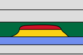
[edit]Structural traps are formed as a result of changes in the structure of the subsurface from processes such as folding and faulting, leading to the formation of domes, anticlines, and folds.[15] Examples of this kind of trap are an anticline trap,[16] a fault trap, and a salt dome trap. They are more easily delineated and more prospective than their stratigraphic counterparts, with the majority of the world's petroleum reserves being found in structural traps.
- Structural traps | blue: source rock, yellow: reservoir rock, green: cap rock, red: hydrocarbons
-
 Structural trap within an anticline
 -
 Structural trap along a fault plane
 -
 Structural-stratigraphic trap in a tilted block draped by mudstones
.svg)


Stratigraphic traps
[edit]Stratigraphic traps are formed as a result of lateral and vertical variations in the thickness, texture, porosity, or lithology of the reservoir rock. Examples of this type of trap are an unconformity trap, a lens trap and a reef trap.[17]
- Stratigraphic traps – blue: source rock, yellow: reservoir rock, green: cap rock, red: hydrocarbons
-
 Stratigraphic trap under an unconformity
 -
 Stratigraphic trap in a fossilized coral reef (yellow) sealed by mudstones (green)
 -
 Stratigraphic trap around an evaporite (pink) salt dome


Hydrodynamic traps
[edit]Hydrodynamic traps are a far less common type of trap.[18] They are caused by the differences in water pressure, that are associated with water flow, creating a tilt of the hydrocarbon-water contact.
Seal / cap rock
[edit]The seal (also referred to as a cap rock) is a fundamental part of the trap that prevents hydrocarbons from further upward migration. A capillary seal is formed when the capillary pressure across the pore throats is greater than or equal to the buoyancy pressure of the migrating hydrocarbons. They do not allow fluids to migrate across them until their integrity is disrupted, causing them to leak. There are two types of capillary seal[19] whose classifications are based on the preferential mechanism of leaking: the hydraulic seal and the membrane seal.
A membrane seal will leak whenever the pressure differential across the seal exceeds the threshold displacement pressure, allowing fluids to migrate through the pore spaces in the seal. It will leak just enough to bring the pressure differential below that of the displacement pressure and will reseal.[20]
A hydraulic seal occurs in rocks that have a significantly higher displacement pressure such that the pressure required for tension fracturing is actually lower than the pressure required for fluid displacement—for example, in evaporites or very tight shales. The rock will fracture when the pore pressure is greater than both its minimum stress and its tensile strength then reseal when the pressure reduces and the fractures close.
Unconventional reservoirs
[edit]
Unconventional (oil and gas) reservoirs are accumulations where oil and gas phases are tightly bound to the rock fabric by strong capillary forces, requiring specialised measures for evaluation and extraction.[21] Unconventional reservoirs form in completely different ways to conventional reservoirs, the main difference being that they do not have "traps". This type of reservoir can be driven in a unique way as well, as buoyancy might not be the driving force for oil and gas accumulation in such reservoirs. This is analogous to saying that the oil which can be extracted forms within the source rock itself, as opposed to accumulating under a cap rock. Oil sands are an example of an unconventional oil reservoir.[22]
Unconventional reservoirs and their associated unconventional oil encompass a broad spectrum of petroleum extraction and refinement techniques, as well as many different sources.[23] Since the oil is contained within the source rock, unconventional reservoirs require that the extracting entity function as a mining operation rather than drilling and pumping like a conventional reservoir. This has tradeoffs, with higher post-production costs associated with complete and clean extraction of oil being a factor of consideration for a company interested in pursuing a reservoir. Tailings are also left behind, increasing cleanup costs. Despite these tradeoffs, unconventional oil is being pursued at a higher rate because of the scarcity of conventional reservoirs around the world.
Estimating reserves
[edit]After the discovery of a reservoir, a petroleum engineer will seek to build a better picture of the accumulation. In a simple textbook example of a uniform reservoir, the first stage is to conduct a seismic survey to determine the possible size of the trap. Appraisal wells can be used to determine the location of oil-water contact and with it the height of the oil bearing sands. Often coupled with seismic data, it is possible to estimate the volume of an oil-bearing reservoir.
The next step is to use information from appraisal wells to estimate the porosity of the rock. The porosity of an oil field, or the percentage of the total volume that contains fluids rather than solid rock, is 20–35% or less. It can give information on the actual capacity. Laboratory testing can determine the characteristics of the reservoir fluids, particularly the expansion factor of the oil, or how much the oil expands when brought from the high pressure and high temperature of the reservoir to a "stock tank" at the surface.
With such information, it is possible to estimate how many "stock tank" barrels of oil are located in the reservoir. Such oil is called the stock tank oil initially in place. As a result of studying factors such as the permeability of the rock (how easily fluids can flow through the rock) and possible drive mechanisms, it is possible to estimate the recovery factor, or what proportion of oil in place can be reasonably expected to be produced. The recovery factor is commonly 30–35%, giving a value for the recoverable resources.[24]
The difficulty is that reservoirs are not uniform. They have variable porosities and permeabilities and may be compartmentalized, with fractures and faults breaking them up and complicating fluid flow. For this reason, computer modeling of economically viable reservoirs is often carried out. Geologists, geophysicists, and reservoir engineers work together to build a model that allows simulation of the flow of fluids in the reservoir, leading to an improved estimate of the recoverable resources.
Reserves are only the part of those recoverable resources that will be developed through identified and approved development projects. Because the evaluation of reserves has a direct impact on the company or the asset value, it usually follows a strict set of rules or guidelines.
Production
[edit]To obtain the contents of the oil reservoir, it is usually necessary to drill into the Earth's crust, although surface oil seeps exist in some parts of the world, such as the La Brea Tar Pits in California and numerous seeps in Trinidad. Factors that affect the quantity of recoverable hydrocarbons in a reservoir include the fluid distribution in the reservoir, initial volumes of fluids in place, reservoir pressure, fluid and rock properties, reservoir geometry, well type, well count, well placement, development concept, and operating philosophy.[24][25]
Modern production includes thermal, gas injection, and chemical methods of extraction to enhance oil recovery.[26]
Drive mechanisms
[edit]A virgin reservoir may be under sufficient pressure to push hydrocarbons to the surface. As the fluids are produced, the pressure will often decline, and production will falter. The reservoir may respond to the withdrawal of fluid in a way that tends to maintain the pressure. Artificial drive methods may be necessary.
Solution-gas drive
[edit]This mechanism (also known as depletion drive) depends on the associated gas of the oil. The virgin reservoir may be entirely semi-liquid but will be expected to have gaseous hydrocarbons in solution due to the pressure. As the reservoir depletes, the pressure falls below the bubble point, and the gas comes out of solution to form a gas cap at the top. This gas cap pushes down on the liquid helping to maintain pressure.
This occurs when the natural gas is in a cap below the oil. When the well is drilled the lowered pressure above means that the oil expands. As the pressure is reduced it reaches bubble point, and subsequently the gas bubbles drive the oil to the surface. The bubbles then reach critical saturation and flow together as a single gas phase. Beyond this point and below this pressure, the gas phase flows out more rapidly than the oil because of its lowered viscosity. More free gas is produced, and eventually the energy source is depleted. In some cases depending on the geology the gas may migrate to the top of the oil and form a secondary gas cap. Some energy may be supplied by water, gas in water, or compressed rock. These are usually minor contributions with respect to hydrocarbon expansion.
By properly managing the production rates, greater benefits can be had from solution-gas drives. Secondary recovery involves the injection of gas or water to maintain reservoir pressure. The gas/oil ratio and the oil production rate are stable until the reservoir pressure drops below the bubble point when critical gas saturation is reached. When the gas is exhausted, the gas/oil ratio and the oil rate drops, the reservoir pressure has been reduced, and the reservoir energy is exhausted.
Gas cap drive
[edit]In reservoirs already having a gas cap (the virgin pressure is already below bubble point), the gas cap expands with the depletion of the reservoir, pushing down on the liquid sections applying extra pressure. This is present in the reservoir if there is more gas than can be dissolved in the reservoir. The gas will often migrate to the crest of the structure. It is compressed on top of the oil reserve, as the oil is produced the cap helps to push the oil out. Over time the gas cap moves down and infiltrates the oil, and the well will produce more and more gas until it produces only gas.
It is best to manage the gas cap effectively, that is, placing the oil wells such that the gas cap will not reach them until the maximum amount of oil is produced. Also a high production rate may cause the gas to migrate downward into the production interval. In this case, over time the reservoir pressure depletion is not as steep as in the case of solution-based gas drive. In this case, the oil rate will not decline as steeply but will depend also on the placement of the well with respect to the gas cap. As with other drive mechanisms, water or gas injection can be used to maintain reservoir pressure. When a gas cap is coupled with water influx, the recovery mechanism can be highly efficient.
Aquifer (water) drive
[edit]Water (usually salty) may be present below the hydrocarbons. Water, as with all liquids, is compressible to a small degree. As the hydrocarbons are depleted, the reduction in pressure in the reservoir allows the water to expand slightly. Although this unit expansion is minute, if the aquifer is large enough this will translate into a large increase in volume, which will push up on the hydrocarbons, maintaining pressure.
With a water-drive reservoir, the decline in reservoir pressure is very slight; in some cases, the reservoir pressure may remain unchanged. The gas/oil ratio also remains stable. The oil rate will remain fairly stable until the water reaches the well. In time, the water cut will increase, and the well will be watered out.[27]
The water may be present in an aquifer (but rarely one replenished with surface water). This water gradually replaces the volume of oil and gas that is produced out of the well, given that the production rate is equivalent to the aquifer activity. That is, the aquifer is being replenished from some natural water influx. If the water begins to be produced along with the oil, the recovery rate may become uneconomical owing to the higher lifting and water disposal costs.
Water and gas injection
[edit]If the natural drives are insufficient, as they very often are, then the pressure can be artificially maintained by injecting water into the aquifer or gas into the gas cap.
Gravity drainage
[edit]The force of gravity will cause the oil to move downward of the gas and upward of the water. If vertical permeability exists then recovery rates may be even better.
Gas and gas condensate reservoirs
[edit]These occur if the reservoir conditions allow the hydrocarbons to exist as a gas. Retrieval is a matter of gas expansion. Recovery from a closed reservoir (i.e., no water drive) is very good, especially if bottom hole pressure is reduced to a minimum (usually done with compressors at the wellhead). Any produced liquids are light-colored to colorless, with a gravity higher than 45 API. Gas cycling is the process where dry gas is injected and produced along with condensed liquid.
See also
[edit]References
[edit]- ^ API Executive Committee on Standardization of Oilfield Equipment and Materials (January 1, 1988). "Glossary of Oilfield Production Terminology" (PDF). Dallas: American Petroleum Institute. Archived (PDF) from the original on 29 December 2010. Retrieved 10 February 2020.
- ^ Gillis, Gretchen. "oil field – Schlumberger Oilfield Glossary". www.glossary.oilfield.slb.com. Retrieved 2020-02-11.
- ^ Li, Guoyu (2011). World atlas of oil and gas basins. Wiley-Blackwell. ISBN 978-1-4443-9005-6. OCLC 707075078.
- ^ Staniford, Stuart (May 2007). "Depletion Levels in Ghawar". www.321energy.com. Archived from the original on 2016-05-29. Retrieved 2021-11-23.
- ^ "Foreign Policy: The List: Taking Oil Fields Offline". August 2006. Archived from the original on 2006-08-20. Retrieved 2021-11-23.
- ^ Yergin, Daniel (1991). The Prize: The Epic Quest for Oil, Money, and Power. New York: Simon & Schuster. ISBN 0-671-50248-4.
- ^ "A Famed Dry Hole Gets a Second Shot", The Wall Street Journal, 21 July 2008, p. B1
- ^ "The Making of Oil: Birth of a Reservoir". Schlumberger Excellence in Educational Development. Archived from the original on November 20, 2005. Retrieved January 30, 2006.
- ^ a b "What is a Reservoir?". Schlumberger Excellence in Educational Development. Archived from the original on April 27, 2006. Retrieved January 30, 2006.
- ^ "Rise and Fall of the North Sea". Schlumberger Excellence in Educational Development. Archived from the original on November 22, 2005. Retrieved January 30, 2006.
- ^ "What is a Reservoir? What are some characteristics?". Schlumberger Excellence in Educational Development. Archived from the original on August 16, 2011. Retrieved January 30, 2006.
- ^ Zongli, Liu; Zhuwen, Wang; Dapeng, Zhou; Shuqin, Zhao; Min, Xiang (2017-05-31). "Pore Distribution Characteristics of the Igneous Reservoirs in the Eastern Sag of the Liaohe Depression". Open Geosciences. 9 (1): 161–173. Bibcode:2017OGeo....9...14Z. doi:10.1515/geo-2017-0014. ISSN 2391-5447.
- ^ Gluyas, J; Swarbrick, R (2004). Petroleum Geoscience. Blackwell Publishing. ISBN 978-0-632-03767-4.
- ^ Basin Analysis: Principles and Applications. Allen, P.A. & Allen, J.R. (2005). Second Edition. Publ. Blackwell Publishing
- ^ "Structural traps". Archived from the original on 2015-02-14. Retrieved 2012-02-02.
- ^ "Schlumberger – Search Results".
- ^ "The Oil Trap". Archived from the original on 2013-01-23. Retrieved 2012-02-02.
- ^ Gluyas, J; Swarbrick, R (2004). Petroleum Geoscience. Blackwell Publishing. p. 148. ISBN 978-0-632-03767-4.
- ^ Watts, N.L., 1987, Theoretical aspects of cap-rock and fault seals for single- and two-phase hydrocarbon columns, Marine & Petroleum Geology, 4, 274-307.
- ^ Peter J. Ortoleva (1994). "Basin compartments and seals". AAPG Memoir. 61. AAPG: 34. ISBN 9780891813408. Retrieved 15 March 2012.
- ^ SPE (2018). Petroleum Resource Management System (revised June 2018) (1.01 ed.). Society of Petroleum Engineers. p. 52. ISBN 978-1-61399-660-7.
- ^ JIA, Chengzao (2017). "Breakthrough and significance of unconventional oil and gas to classical petroleum geology theory". Petroleum Exploration and Development. 44 (1): 1–10. doi:10.1016/s1876-3804(17)30002-2. ISSN 1876-3804.
- ^ "Oil". 2016-04-05. Archived from the original on 2016-04-05. Retrieved 2021-11-02.
- ^ a b Babadagli, Tayfun (2007). "Development of mature oil fields — A review". Journal of Petroleum Science and Engineering. 57 (3–4): 221–246. doi:10.1016/j.petrol.2006.10.006.
- ^ Lawal, Kazeem A.; Yadua, Asekhame U.; Ovuru, Mathilda I.; Okoh, Oluchukwu M.; Eyitayo, Stella I.; Matemilola, Saka; Olamigoke, Olugbenga (2020-03-01). "Rapid screening of oil-rim reservoirs for development and management". Journal of Petroleum Exploration and Production Technology. 10 (3): 1155–1168. doi:10.1007/s13202-019-00810-6. ISSN 2190-0566.
- ^ Alvarado, Vladimir; Manrique, Eduardo (2010-08-27). "Enhanced Oil Recovery: An Update Review". Energies. 3 (9): 1529–1575. doi:10.3390/en3091529. ISSN 1996-1073.
- ^ Schlumberger Energy Glossary. "waterdrive". glossary.slb.com. Retrieved 2023-02-12.
Petroleum reservoir
View on GrokipediaFundamentals and Classification
Definition and Key Characteristics
A petroleum reservoir is a subsurface accumulation of crude oil, natural gas, or both, contained within porous and permeable rock formations, where hydrocarbons have migrated from source rocks and become trapped by structural, stratigraphic, or combination mechanisms that prevent further escape.[8] These reservoirs form under specific geological conditions, including adequate generation, migration, and entrapment of hydrocarbons, with the rock matrix providing interconnected pore spaces for storage and transmission.[9] Economic viability requires the rock to exhibit sufficient storage capacity and flow potential to allow commercial extraction via wells.[5] Key physical properties defining reservoir performance include porosity (φ), the fraction of the bulk rock volume occupied by void spaces available for fluids, and permeability (k), the measure of the rock's ability to transmit fluids through those interconnected pores under a pressure gradient, typically quantified using Darcy's law. Porosity in viable reservoirs generally ranges from 5% to 30%, with higher values enhancing storage but often correlating inversely with mechanical strength; permeability varies widely from less than 1 millidarcy (md) in tight formations to over 1,000 md in highly productive sands, directly influencing production rates and recovery efficiency.[4][8][5] Fluid saturations—proportions of oil (S_o), gas (S_g), and irreducible water (S_w)—sum to unity and govern initial in-place volumes, with hydrocarbons buoyantly displacing water due to density differences; capillary forces and wettability (preferential adhesion to rock surfaces) further control phase distribution and multiphase flow behavior.[8][9] Additional characteristics encompass reservoir pressure, temperature, and drive mechanisms, which dictate fluid phase behavior and depletion dynamics: solution gas drive relies on liberated gas expansion as pressure drops below bubble point, while water drive involves aquifer influx maintaining pressure. Compressibility of the rock framework and fluids affects volumetric changes under depletion, with bulk compressibility (c_b = c_f + c_o + S_w c_w, where subscripts denote fluids and rock) typically on the order of 10^{-6} to 10^{-5} psi^{-1} for sandstones. Heterogeneity in these properties, arising from depositional environments and diagenesis, introduces spatial variability that complicates uniform flow and necessitates advanced characterization for accurate modeling.[4]Types of Reservoirs: Oil, Gas, and Condensate
Petroleum reservoirs are classified primarily by the type of hydrocarbon fluids they contain and their phase behavior under reservoir pressure and temperature conditions, as determined through pressure-volume-temperature (PVT) analysis of fluid samples. Oil reservoirs hold liquid hydrocarbons (crude oil) as the dominant phase, often with dissolved natural gas; gas reservoirs contain predominantly gaseous hydrocarbons; and condensate reservoirs feature gas-rich fluids that yield significant liquid hydrocarbons upon pressure reduction at the surface or within the reservoir. This classification influences extraction methods, recovery factors, and economic viability, with oil reservoirs typically exhibiting lower gas-to-oil ratios (GOR) below 2,000 standard cubic feet per barrel (scf/bbl), gas reservoirs showing GOR exceeding 3,000 scf/bbl with minimal liquids, and condensate systems displaying retrograde condensation where liquids form upon depletion below the dew point.[10][11] Oil reservoirs are subdivided into black oil and volatile oil types based on fluid composition and PVT properties. Black oil systems, characterized by high stock-tank oil density (typically >0.85 g/cm³) and low solution GOR (<0.5 m³/m³ or ~2,800 scf/bbl), remain in the two-phase region (oil and gas) at reservoir conditions below the bubble-point pressure, with asphaltene and resin content contributing to higher viscosity (often 1-10 cP). Volatile oil reservoirs, by contrast, have lighter compositions with GOR up to 3,000 scf/bbl, lower densities (<0.72 g/cm³), and bubble points approaching reservoir temperatures, leading to substantial gas liberation upon production and higher shrinkage factors (up to 4-5 times volume reduction to stock-tank conditions). These distinctions are empirically derived from PVT laboratory data, where black oils show initial gas in solution ratios correlating with API gravity below 45°, while volatile oils exceed this threshold, affecting drive mechanisms like solution gas drive in undersaturated reservoirs.[12][13] Gas reservoirs consist of dry gas and wet gas subtypes, differentiated by condensate yield and composition. Dry gas reservoirs produce methane-dominated fluids (>90% C1) with negligible liquid dropout (condensate-gas ratio <0.1 bbl/MMscf), behaving as single-phase gases above the cricondentherm on phase envelopes, enabling high recovery rates (up to 90%) via pressure depletion without significant phase changes. Wet gas systems yield more liquids (0.1-20 bbl/MMscf) from heavier components (C2-C5), yet remain gaseous in situ, with PVT data indicating higher compressibility and lower methane fractions (70-85%), as observed in fields like those in the North Sea where empirical correlations link initial gas composition to liquid dropout under isothermal depletion.[13][14] Condensate reservoirs, also termed retrograde gas or gas-condensate systems, operate in a pressure-temperature regime between the critical point and cricondentherm, where the fluid exists as a single gas phase initially but undergoes retrograde condensation—forming liquid hydrocarbons (maximum 20-30% of volume) as pressure drops below the dew point, potentially reducing relative permeability to gas by up to 50% due to liquid banking near the wellbore. These reservoirs typically exhibit high initial GOR (>5,000 scf/bbl equivalent) and low stock-tank liquid density (<0.65 g/cm³), with empirical PVT studies showing dew points around 1,000-5,000 psi and condensate yields peaking at 100-300 bbl/MMscf, as in Arun field data where composition analysis revealed C7+ fractions driving the phase envelope's retrograde loop. Recovery challenges arise from this condensation, often mitigated by pressure maintenance via gas cycling, contrasting with simpler depletion in dry gas systems.[14][15]Historical Context
Early Discoveries and Geological Insights
The earliest subsurface petroleum reservoirs were exploited following Edwin Drake's successful well drilled to 69.5 feet on August 27, 1859, near Titusville, Pennsylvania, which tapped into a Devonian-age sandstone formation along Oil Creek and initiated commercial production at rates up to 25 barrels per day.[16] This discovery, driven by surface seeps observed in the region since prehistoric times, marked the shift from incidental collections to intentional deep drilling for hydrocarbons trapped in porous reservoir rocks, though initial yields declined rapidly due to rudimentary extraction methods. Prior to 1859, petroleum was primarily sourced from shallow pits or brine well byproducts in areas like Pennsylvania and Kentucky, with limited recognition that accumulations formed in specific subsurface geological structures rather than uniformly distributed.[17] Post-1859 boom in the Pennsylvania oil fields prompted initial geological mapping, revealing that productive reservoirs often aligned with anticlinal folds where impermeable cap rocks trapped upward-migrating hydrocarbons in permeable sandstones or limestones.[18] By 1861, geologist Sterry Hunt articulated the anticlinal theory, positing that oil and gas accumulate preferentially in structural highs due to buoyancy-driven migration and gravitational segregation, with gas overlying oil in the same trap—a concept independently proposed by others like William Logan in Canada.[19] Empirical observations from fields like Oil Creek confirmed that dry holes frequently occurred off-structure, leading to practices of surface prospecting for anticlines via topographic highs or fault traces by the 1870s, though successes remained probabilistic without subsurface data.[20] Further insights emerged from East Texas and Canadian fields in the late 19th century, where fault-related traps and stratigraphic variations were noted alongside anticlines, expanding understanding beyond pure structural controls to hybrid mechanisms involving rock porosity and permeability.[18] These early deductions, grounded in field mappings and well logs rather than advanced geophysics, established causal links between tectonic deformation, sedimentation, and reservoir formation, influencing exploration strategies despite prevailing skepticism from uniformitarian geologists who viewed oil origins as abiogenic.[21] By the 1890s, cumulative production data from Appalachian basin reservoirs underscored the finite nature of traps, prompting rudimentary volumetric estimates based on observed thicknesses of pay zones, typically 10-50 feet in Silurian-Devonian sands.[22]Development of Reservoir Engineering Principles
The principles of reservoir engineering emerged in the early 20th century amid growing petroleum production demands, transitioning from ad hoc drilling and empirical recovery techniques to systematic fluid dynamics analysis. Prior to the 1920s, reservoir management largely depended on observational practices, such as monitoring pressure declines and well productivity without underlying mathematical frameworks, as seen in early fields like those in Pennsylvania and Texas. The foundational shift occurred with the extension of Darcy's law—originally an empirical relation for laminar flow through unconsolidated sands derived in 1856—to multiphase hydrocarbon systems in porous reservoir rocks, enabling quantification of flow rates driven by pressure gradients. This adaptation, formalized during the 1920s, marked the onset of applying classical fluid mechanics to underground reservoirs, where permeability and viscosity became central parameters for predicting single-phase fluid movement.[23][24] By the 1930s, petrophysical investigations laid groundwork for characterizing rock-fluid interactions, with Fancher, Lewis, and Barnes conducting seminal core analyses in 1933 to measure porosity, permeability, and wettability in sandstone reservoirs, revealing quantitative links between rock microstructure and fluid storage capacity. Concurrently, Wycoff, Botset, Muskat, and Meres advanced relative permeability concepts in 1934 through laboratory experiments on two-phase flow, demonstrating how saturation-dependent permeability alters displacement efficiency during production. These efforts culminated in Morris Muskat's 1937 treatise The Flow of Homogeneous Fluids Through Porous Media, which integrated Darcy's law with continuity equations to derive the diffusivity equation for transient pressure behavior in reservoirs, providing tools for well test interpretation and interference analysis. The material balance equation, initially conceptualized around 1914 for volumetric conservation and rigorously developed by Schilthuis in 1936, further enabled reserve estimation by equating initial fluid volumes to expansions, productions, and compressions under varying pressures, validated against field data from undersaturated oil systems.[25][26] Post-World War II advancements refined displacement mechanisms, notably through Buckley and Leverett's 1942 frontal advance theory, which modeled immiscible water-oil displacement via fractional flow functions derived from relative permeability curves, predicting saturation profiles and breakthrough times in linear systems despite simplifying assumptions like piston-like flow. This Buckley-Leverett framework, tested against core floods, highlighted viscous fingering limitations and spurred numerical extensions for heterogeneous reservoirs. By the 1940s, these principles coalesced into a discipline focused on optimizing recovery factors, with empirical validation from major fields demonstrating that material balance and flow models could forecast performance more accurately than intuition alone, reducing overproduction risks and informing pressure maintenance strategies.[27][28]Geological Formation and Structure
Origin and Migration Processes
Petroleum originates primarily from the accumulation and transformation of organic matter in sedimentary basins. Organic-rich source rocks form when plankton, algae, and higher plants settle in anoxic marine or lacustrine environments, undergoing early diagenesis to produce insoluble kerogen, a complex macromolecular substance composed of condensed hydrocarbons and heteroatoms.[29] Kerogen types are classified based on hydrogen index and atomic H/C ratios: Type I (algal-derived, lipid-rich, yielding mostly oil); Type II (mixed marine-terrestrial, generating oil and gas); Type III (woody, humic, gas-prone); and Type IV (oxidized, inert, low yield).[30] During burial, increasing geothermal gradients drive kerogen maturation through catagenesis, where temperatures of 50–150°C induce thermal cracking, releasing hydrocarbons as liquid oil (primarily from Types I and II at 60–120°C, the "oil window") or methane-dominated gas (from further cracking or Type III at >120°C). Vitrinite reflectance (Ro) measures maturity, with oil generation peaking at Ro 0.6–1.3% and dry gas at Ro >2.0%. This process expels hydrocarbons via overpressure in compacting source rocks, with expulsion efficiency varying from 10–80% depending on organic richness (TOC >2%) and mineral matrix.[31][32] Primary migration involves the release of newly generated hydrocarbons from kerogen within fine-grained source rocks into coarser carrier beds, facilitated by hydrodynamic flow, diffusion, and microfractures under elevated pore pressure exceeding 0.8–1.0 times hydrostatic. Secondary migration follows, as buoyant hydrocarbons (density 0.6–0.9 g/cm³ versus water's 1.0 g/cm³) ascend through permeable strata like sandstones, often tens to hundreds of kilometers laterally and vertically, until trapped by impermeable seals. Migration distances can exceed 100 km, with phase separation occurring where gas escapes upward faster than oil.[33][34][35]Trap Mechanisms
Trap mechanisms in petroleum reservoirs refer to geological configurations that impede the upward migration of hydrocarbons, enabling their accumulation beneath an impermeable seal. Hydrocarbons, generated from kerogen in source rocks through thermal maturation, migrate buoyantly via primary (through source rock pores) and secondary (along carrier beds) processes until encountering a trap sealed by cap rock, typically shale or evaporites, which prevents further escape.[36] The efficacy of a trap depends on its closure area, vertical relief, and seal integrity, with hydrocarbons stratifying by density—gas overlying oil—due to gravitational segregation.[37] Structural traps arise from tectonic deformation of reservoir strata, creating relative highs that retain hydrocarbons. Anticlines, formed by compressional folding, position porous rock at the crest under a conformable seal, as seen in many prolific fields where arching provides spill points defining trap limits. Fault traps develop from displacement along fault planes, juxtaposing permeable reservoir against impermeable units or sealing via clay smears and gouge; normal faults in extensional basins often enhance trapping when throw exceeds reservoir thickness.[38] These traps dominate conventional discoveries, with structural complexity influencing migration pathways and seal effectiveness.[36] Stratigraphic traps form without significant tectonic distortion, relying on lateral or vertical facies changes from depositional or diagenetic processes. Pinch-out traps occur where reservoir quality diminishes laterally into non-porous lithologies, such as sandstones grading into shales; unconformity traps exploit erosion surfaces draping older reservoirs with sealing strata. Reef and bioherm traps involve porous carbonate buildups encased in impermeable mudstones, while salt domes pierce reservoirs, creating four-way dip closures.[39] These traps require precise timing between deposition, migration, and sealing to avoid leakage.[38] Combination traps integrate structural and stratigraphic elements, such as faulted anticlines with lateral pinch-outs, amplifying closure volume and reducing spill risk. Hydrodynamic traps, less common, involve tilted water tables from aquifer flow modifying buoyancy-driven accumulation, tilting interfaces away from structural highs.[37] Trap integrity ultimately governs reservoir charge, with breaches via fault reactivation or seal fracturing leading to dry holes despite viable source and reservoir.[36]Reservoir Rock Properties: Porosity and Permeability
Porosity refers to the fraction of a rock's bulk volume occupied by void spaces, or pores, which determines the storage capacity for hydrocarbons in petroleum reservoirs. It is typically expressed as a decimal fraction or percentage, with values in effective reservoir rocks ranging from 5% to 30% depending on lithology; for instance, sandstones often exhibit 10-25% porosity, while carbonates may vary from 5-20%. Effective porosity, the portion of pore volume interconnected and accessible to fluids, excludes isolated pores and is critical for fluid flow, unlike total porosity which includes all voids. Primary porosity arises from depositional processes, such as intergranular spaces in clastic sediments, whereas secondary porosity forms post-depositionally through mechanisms like dissolution of grains or cement, fracturing, or dolomitization, which can enhance storage but vary in connectivity.[4][5][40] Permeability quantifies a rock's capacity to transmit fluids under a pressure gradient, governed by Darcy's law, and is measured in darcies (D) or millidarcies (md), where 1 D equals approximately 9.869 × 10^{-13} m²; reservoir rocks typically require permeabilities above 1 md for economic production, though tight reservoirs may function at 0.1 md or less with stimulation. Unlike porosity, permeability depends not just on pore volume but on pore size, shape, and interconnectivity, with larger, well-connected throats facilitating higher flow rates. Factors influencing permeability include grain size and sorting—coarser, uniformly sorted sands yield higher values—along with diagenetic alterations like cementation, which reduces it, or fracturing, which can increase it anisotropically. Confining pressure from overburden compacts pores, diminishing both properties, while bedding planes may create directional variations, with vertical permeability often lower than horizontal in layered formations.[41][4][42] Wait, no wiki; use alternative: [43] Although porosity and permeability both stem from pore architecture, they are not linearly correlated; rocks can exhibit high porosity but low permeability if pores are isolated or throats are narrow, as in shales (porosity up to 10% but permeability <0.001 md), versus clean sandstones where permeability scales with the square of pore throat radius per Kozeny-Carman models. Empirical data from core analyses show scatter, with carbonates displaying wider variability due to vuggy or moldic pores that boost storage but hinder uniform flow. Laboratory measurements provide direct values: porosity via helium porosimetry on core plugs, saturating samples to displace gas and compute void fraction; permeability via steady-state gas or liquid injection under controlled pressure differentials. In situ estimates derive from well logs (e.g., density-neutron for porosity, formation testers for permeability) or production tests, calibrated against cores for accuracy.[4][44][45]Unconventional Reservoirs
Unconventional reservoirs are petroleum accumulations characterized by ultra-low permeability, typically less than 0.1 millidarcy (md), and low porosity, often below 10%, which preclude economic production without extensive stimulation techniques such as hydraulic fracturing and horizontal drilling.[46][47] Unlike conventional reservoirs, where hydrocarbons migrate into porous traps under buoyancy and produce via natural pressure gradients, unconventional reservoirs feature hydrocarbons tightly bound within the source rock or adjacent tight formations, with continuous or quasi-continuous distributions lacking discrete trap boundaries or uniform fluid contacts.[47] This results in nanometer-scale pore-throat networks and limited migration, requiring artificial permeability enhancement to achieve commercial flow rates.[47] Principal types include shale gas and shale oil (tight oil), tight gas sands, coalbed methane (CBM), and, in broader classifications, heavy oil, tar sands, oil shales, and gas hydrates. Shale gas reservoirs, for instance, consist of organic-rich shales with total organic carbon content ranging from 0.5% to 25%, where gas is stored as free gas, adsorbed gas, or dissolved in organics.[46] Tight gas formations exhibit similar low permeability but in sandstones or carbonates, while CBM involves methane adsorbed onto coal matrices formed over 400 million years ago, necessitating reservoir depressurization via dewatering.[46] Examples include the Bakken Formation for tight oil in the United States and the Sulige field for tight gas in China.[47] Geologically, these reservoirs form in basin centers or slopes with minimal structural deformation, relying on stratigraphic continuity rather than anticlinal or fault traps for retention. Production demands multi-stage hydraulic fracturing to create fracture networks that connect the low-permeability matrix to the wellbore, often combined with multilateral horizontal wells spanning thousands of feet.[46][48] Global resource estimates, such as those from 1996 data, indicate substantial volumes, with shale gas alone at approximately 16,103 trillion cubic feet (Tcf) worldwide.[46] Challenges encompass high stimulation costs, variable well performance due to heterogeneous rock properties, and operational risks like induced seismicity from fracturing, though advancements in fracture diagnostics and chemical stimulation have improved recovery in plays like the Ordos Basin.[48] Economic viability hinges on commodity prices, with U.S. shale developments since the 2000s demonstrating scalability through repeated drilling and completion optimizations.[48]Fluid Dynamics and Properties
Phase Behavior and PVT Analysis
Phase behavior of petroleum reservoir fluids refers to the conditions under which hydrocarbon mixtures transition between gaseous, liquid, and two-phase states, governed primarily by pressure, temperature, and composition. In subsurface reservoirs, hydrocarbons exist as complex mixtures originating from kerogen maturation, with lighter components more volatile and prone to vaporization as pressure declines during production. This behavior is critical because reservoir pressure often exceeds the bubble-point pressure for oils or dew-point for gases at initial conditions, maintaining a single-phase state; depletion can induce phase separation, liberating gas from oil or condensing liquids from gas, which alters mobility, relative permeability, and recovery efficiency. Accurate prediction relies on empirical PVT data rather than idealized models, as real fluids deviate from pure-component thermodynamics due to molecular interactions and impurities like asphaltenes.[49][50] PVT analysis involves laboratory measurements on representative fluid samples to quantify volumetric and thermodynamic properties under simulated reservoir conditions, typically using recombined bottomhole or separator samples pressurized to avoid phase changes during retrieval. Core properties include formation volume factor (B_o for oil, volume at reservoir conditions per stock-tank volume), solution gas-oil ratio (R_s, standard cubic feet of gas per stock-tank barrel of oil dissolved at bubble point), oil and gas viscosity (μ_o, μ_g), density (ρ_o, ρ_g), and isothermal compressibility (c_o), all measured via experiments like constant composition expansion (CCE) for phase envelopes and swelling tests, differential liberation (DL) mimicking reservoir depletion, and constant volume depletion (CVD) for gas condensates. For volatile oils and condensates, compositional grading with depth affects these properties, requiring equation-of-state (EOS) modeling tuned to chromatography data for multi-component simulations; black-oil approximations suffice for less volatile systems but underestimate swelling in gas injection scenarios. Sampling errors, such as degassing or contamination, can bias results by up to 20% in R_s or B_o, underscoring the need for single-phase sampling tools and validation against well tests.[51][52][53] These analyses inform material balance equations for initial oil-in-place estimation, where deviations from ideal gas behavior (via Z-factor for gases) reveal drive mechanisms, and enable simulation of pressure-volume relationships to forecast production profiles. In gas condensate reservoirs, retrograde condensation below dew point traps liquids in low-permeability rock, reducing productivity; PVT data quantifies critical gas saturation and liquid dropout, guiding strategies like near-miscible gas cycling to vaporize condensates and boost recovery beyond 50% in some fields. For heavy oils, high viscosity (often >100 cP at reservoir conditions) and asphaltene precipitation during depletion complicate phase stability, with PVT tests identifying minimum miscibility pressures for enhanced recovery. Empirical correlations, such as Standing's for R_s or Glaso's for μ_o, provide quick estimates but must be field-validated, as universal models overlook compositional specifics.[54][55][56]Rock-Fluid Interactions
Rock-fluid interactions in petroleum reservoirs encompass the physicochemical processes between reservoir rocks and hydrocarbons, water, and injected fluids, influencing fluid distribution, multiphase flow, and ultimate recovery. These interactions arise from surface forces, interfacial tensions, and adsorption phenomena at the pore scale, where rock mineralogy—predominantly quartz, carbonates, or clays—interacts with fluid compositions varying in polarity and viscosity.[57] In water-wet systems, water preferentially coats pore surfaces, allowing hydrocarbons to occupy central pore spaces, whereas oil-wet conditions promote hydrocarbon adhesion to rock, altering displacement efficiency during production.[58] Empirical studies demonstrate that optimal recovery often occurs in mixed-wettability reservoirs, where larger pores are oil-wet and smaller ones water-wet, enhancing microscopic sweep by balancing capillary and viscous forces.[59] Wettability, a core aspect of these interactions, quantifies the rock's affinity for one fluid phase over another, measured via contact angle θ (where θ < 90° indicates water-wet and θ > 90° oil-wet) or indices like Amott-Harvey (ranging from -1 for strongly oil-wet to +1 for strongly water-wet).[60] This property profoundly impacts oil recovery; in strongly water-wet reservoirs, waterflooding achieves higher displacement due to favorable relative permeability curves, with oil recovery potentially exceeding 50% of original oil in place (OOIP), compared to less than 30% in oil-wet systems where bypassed oil traps in dead-end pores.[58] [59] Aging cores with crude oil at reservoir conditions (e.g., 80–120°C for weeks) restores natural wettability, revealing that prolonged oil-rock contact induces partial oil-wetness via polar asphaltene adsorption, reducing water imbibition and recovery by up to 20%.[61] Capillary pressure, arising from interfacial tension σ between fluids and rock wettability, governs initial fluid saturations and transition zones in reservoirs, expressed as , where r is pore radius.[62] In water-wet rocks, positive capillary pressure retains water in smaller pores below the oil-water contact, creating a transition zone thickness proportional to , with φ as porosity and k as permeability; for typical sandstone reservoirs (k ≈ 100 md, σ ≈ 30 mN/m), this zone spans 10–50 m vertically.[63] High capillary pressures in tight reservoirs (k < 1 md) elevate connate water saturation to 40–60%, limiting movable hydrocarbons, while imbibition capillary forces drive spontaneous water invasion, contributing 10–20% additional recovery in water-wet carbonates.[64] Relative permeability , the fractional permeability to a phase amid others, depends critically on wettability, saturation history, and interactions like clay swelling or fines migration.[65] Water-wet conditions yield higher oil at residual saturations due to central oil ganglia mobilization, whereas oil-wet rocks exhibit piston-like displacement with lower critical water saturation (Swcr ≈ 20–30% vs. 40% in water-wet).[58] In enhanced oil recovery (EOR), altering wettability toward water-wet via surfactants reduces interfacial tension and shifts curves, boosting recovery by 5–15% OOIP; for instance, low-salinity water injection expands electrical double layers, detaching oil films and improving by 10–20%.[57] [66] Adsorption of heavy components like asphaltenes onto clays further complicates flow, potentially halving permeability in high-clay reservoirs (clay content > 10%).[67] These interactions extend to chemical alterations during EOR, where injected fluids (e.g., CO2 or polymers) induce mineral dissolution—such as calcite in carbonates—enhancing porosity by 1–5% but risking permeability damage via precipitation if incompatible.[68] In unconventional reservoirs, high surface areas amplify adsorption, with organic matter preferring oil-wet states that trap kerogen-derived hydrocarbons, necessitating tailored fracturing fluids to mitigate capillary end-effects.[69] Accurate quantification via corefloods at reservoir pressure-temperature (e.g., 3000–5000 psi, 80–150°C) is essential, as lab mismatches can overestimate recovery by 10–30%.[70]Exploration and Characterization
Geophysical and Drilling Methods
Geophysical methods provide non-invasive subsurface imaging to identify potential petroleum reservoirs, with seismic reflection surveying serving as the cornerstone technique for delineating trap structures, stratigraphy, and fluid distributions. This method generates acoustic waves, primarily compressional P-waves, via controlled sources such as vibroseis trucks or air guns, which propagate through rock layers and reflect at interfaces with acoustic impedance contrasts, allowing receivers to record echoes for processing into 2D, 3D, or 4D images.[71][72] Advanced applications include seismic inversion to estimate rock properties like porosity and seismic attribute analysis for direct hydrocarbon indicators, enhancing reservoir characterization between sparse well data points.[73][74] Complementary geophysical techniques, such as gravity and magnetic surveys, detect density or susceptibility anomalies associated with hydrocarbon traps, though they offer lower resolution than seismic data and are typically integrated for regional screening.[75] In reservoir characterization, time-lapse (4D) seismic monitors fluid movement during production, revealing changes in saturation or pressure that inform dynamic models.[76] These methods collectively reduce exploration risks by quantifying reserves potential prior to drilling, with seismic data pivotal in assessing oil and gas volumes across basins.[75] Drilling methods transition geophysical leads into confirmed reservoirs through exploratory (wildcat) wells, which penetrate target formations to acquire direct samples and logs, typically employing rotary drilling as the dominant technique for depths exceeding 1,000 meters. In rotary drilling, a rotating drill bit attached to a drill string grinds through formations while drilling mud circulates to remove cuttings, stabilize the borehole, and prevent blowouts, enabling vertical or directional trajectories.[77][78] For unconventional reservoirs, horizontal drilling extends laterally within pay zones—often thousands of meters—to maximize contact, as seen in shale plays where vertical sections reach over 6,800 feet before curving.[79] During and post-drilling, well logging techniques characterize reservoir properties in situ, including wireline or logging-while-drilling (LWD) tools that measure gamma ray for lithology, resistivity for fluid saturation, and sonic logs for porosity via compressional and shear wave velocities.[80] These logs integrate with core samples to calibrate geophysical models, estimating parameters like net pay thickness and permeability, while production logging evaluates flow profiles in completed wells to diagnose underperformance.[81] Exploratory campaigns typically span 50-60 days per well, yielding data that refines volumetric estimates and guides appraisal drilling.[82]Reservoir Modeling and Simulation
Reservoir modeling constructs three-dimensional representations of subsurface petroleum accumulations, integrating geological, petrophysical, and fluid data to estimate volumes and predict performance.[83] Static models focus on fixed properties such as porosity, permeability, and structural framework derived from seismic, well logs, and core samples, providing a spatial distribution of rock facies and properties.[84] Dynamic modeling extends this by simulating time-dependent fluid flow using partial differential equations governing multiphase transport, solved numerically via finite difference or finite volume methods.[85] Simulation techniques solve conservation of mass, momentum, and energy equations, often simplified into black-oil models for immiscible systems where oil, water, and gas phases are treated with pseudo-components based on solution gas-oil ratio and formation volume factors.[86] Compositional models, in contrast, track individual hydrocarbon components using equation-of-state thermodynamics, essential for processes like gas injection or enhanced oil recovery involving miscibility.[87] Commercial software such as Eclipse from SLB supports both black-oil and compositional simulations, enabling up to millions of grid cells for full-field studies with robust solvers for speed and accuracy.[88] The workflow begins with geological model upscaling to simulation grids, followed by history matching where model parameters are adjusted to replicate observed production pressures, rates, and saturations from field data, minimizing residuals through optimization algorithms.[89] Uncertainty quantification incorporates probabilistic methods, such as Monte Carlo sampling of input variabilities in porosity, permeability, and relative permeability curves, to generate ensembles of forecast scenarios.[90] Advances include integration of machine learning for faster history matching and hybrid models combining physics-based simulation with data-driven surrogates to handle complex unconventional reservoirs.[91] Challenges persist in computational demands for high-resolution models, particularly in thermal or reactive simulations, with ongoing developments in parallel computing and GPU acceleration reducing run times from weeks to hours.[92] Validation against analytical solutions and field analogs ensures reliability, though over-reliance on history-matched models without causal validation of drive mechanisms can lead to optimistic forecasts.[93]Reserve Assessment
Estimation Techniques
Estimation of petroleum reserves involves applying deterministic or probabilistic methods to quantify recoverable hydrocarbons based on geological, engineering, and production data. Deterministic approaches use fixed values for parameters such as reservoir volume, porosity, and recovery factors to yield a single estimate, while probabilistic methods incorporate statistical distributions to assess uncertainty ranges, often preferred for capturing variability in subsurface data.[94][95] The choice of technique depends on data availability: early-stage appraisals favor volumetric methods, while mature fields rely on production-based analyses like material balance or decline curves.[96] The volumetric method calculates original oil in place (OOIP) as the product of reservoir area (A), net thickness (h), porosity (φ), initial oil saturation (1 - S_w), and formation volume factor (B_o), adjusted for recovery factor (R_f): OOIP = 7758 * A * h * φ * (1 - S_w) / B_o. Recoverable reserves are then OOIP multiplied by R_f, typically 10-50% for conventional reservoirs depending on drive mechanism. This technique requires geophysical mapping and core/log data but assumes static conditions and uniform properties, limiting accuracy in heterogeneous formations.[97] It is widely used for initial assessments in undrilled or appraisal-stage reservoirs.[96] Material balance equations equate reservoir volume changes to production and pressure declines, solving for OOIP via *N_p B_o + W_e = N B_t (1 - S_wc) (B_o - B_oi) + (m) (B_g) (R_so - R_sw), where N is OOIP, N_p is cumulative oil produced, W_e is water influx, and other terms account for gas and expansion effects. Applicable to both oil and gas reservoirs, it integrates PVT data and production history for dynamic estimates, improving reliability over volumetric methods in aquifers-driven fields but requiring representative pressure data.[98] For volumetric gas reservoirs, simplified forms focus on pore volume constancy.[99] Decline curve analysis extrapolates future production from historical trends, fitting exponential (q = q_i *e^{-D t}), hyperbolic (q = q_i / (1 + b D_i t)^{1/b}), or harmonic models to observed rates, integrating to estimate ultimate recovery (EUR = N_p + remaining reserves). Empirical and data-driven, it excels in mature fields with stable decline but overestimates in unconventional reservoirs with variable skin or interference effects; hybrid approaches combining it with flowing material balance enhance accuracy.[100] Advanced simulations, using numerical or semi-analytical models, integrate all data types for probabilistic forecasting, particularly in tight formations where DCA alone suffices less.[101]Classification and Reporting Standards
The classification of petroleum reserves and resources relies on standardized frameworks to ensure consistency, comparability, and reliability in estimation and reporting across the industry. The Society of Petroleum Engineers (SPE) Petroleum Resources Management System (PRMS), last comprehensively updated in 2018 with minor revisions in 2022, serves as the globally recognized standard for defining, classifying, and categorizing hydrocarbon volumes based on project maturity, commercial viability, and uncertainty levels.[102][103] PRMS categorizes resources into reserves (commercially recoverable quantities from known accumulations), contingent resources (discovered but not yet commercial), prospective resources (undiscovered potential), and unrecoverable volumes, with reserves further subdivided by uncertainty into proved (1P, high confidence), probable (2P, best estimate), and possible (3P, low confidence).[104] These classifications incorporate factors such as geological knowledge, development plans, fiscal conditions, and recovery technology, emphasizing probabilistic assessment methods where appropriate.[105] In contrast, the U.S. Securities and Exchange Commission (SEC) mandates reporting standards under Regulation S-K for publicly traded companies, focusing exclusively on proved reserves to mitigate investor risk from speculative estimates.[106] Adopted in 1977 and modernized in 2008 with further amendments in 2020 to accommodate technological advancements like horizontal drilling, SEC rules define proved reserves as those quantities recoverable under existing economic and operating conditions with reasonable certainty, typically using deterministic methods or specific probabilistic thresholds (e.g., 90% probability for proved undeveloped).[106] Pricing for producibility tests must use unweighted average prices from the first day of each month over the prior 12 months, excluding escalations or derivatives, which often results in more conservative estimates compared to PRMS's allowance for forward-looking prices.[107] Non-compliance can lead to regulatory penalties, as seen in enforcement actions against firms overstating reserves, underscoring the SEC's emphasis on verifiable economic thresholds over broader resource potential.[108] Key differences between PRMS and SEC arise from their scopes and methodologies: PRMS enables comprehensive reporting of all resource classes for strategic planning, incorporating risk-weighted volumes and multiple economic scenarios, whereas SEC prioritizes proved reserves only for financial statements, prohibiting disclosure of probable or possible in the same context to avoid misleading optimism.[109] For instance, SEC excludes certain unconventional resources unless analogous reservoir performance data supports reasonable certainty, and it mandates disclosure by geographic area for fields exceeding 15% of total proved reserves.[106] These variances can yield significant estimation gaps; analyses of U.S. fields show SEC proved reserves often 20-50% lower than PRMS equivalents due to stricter certainty and pricing requirements, reflecting SEC's investor-protection rationale amid historical overreporting scandals.[108] Independent audits by qualified reserves evaluators are required under both, but PRMS guidelines stress competence and transparency in evaluation processes.[110] Internationally, equivalents like Canada's National Instrument 51-101 align closely with PRMS but incorporate local regulatory nuances, requiring disclosure of reserves, contingent, and prospective resources with defined evaluation dates.[111] Compliance with these standards facilitates capital allocation and risk assessment, though discrepancies persist due to jurisdictional priorities—PRMS for operational breadth versus SEC's fiscal conservatism—necessitating dual reporting for multinational firms.[112] Empirical data from global audits indicate that adherence reduces estimation volatility, with PRMS updates in 2018 enhancing guidance on low-permeability reservoirs and improved recovery projects to reflect technological maturation.[102]Production and Recovery Processes
Natural Drive Mechanisms
Natural drive mechanisms provide the primary energy for hydrocarbon production in petroleum reservoirs, relying on inherent reservoir conditions such as fluid expansion, aquifer influx, and gravitational forces to displace oil toward producing wells without artificial intervention. These mechanisms determine production behavior, recovery efficiency, and pressure maintenance, with typical recovery factors varying by type and reservoir properties like permeability, viscosity, and structure.[113] The main types include solution gas drive, gas cap drive, water drive, and gravity drainage, often occurring in combinations that influence overall performance.[114] Solution gas drive, also termed depletion drive, dominates in reservoirs lacking significant gas caps or aquifers, where dissolved gas in the oil liberates and expands as pressure falls below the bubble point, propelling oil to the wellbore. This process leads to rapid reservoir pressure decline and a sharp rise in gas-oil ratio (GOR) as free gas accumulates, resulting in lower recovery factors of 5-30% of original oil in place (OOIP).[115][116] Reservoirs exhibiting this mechanism typically show early gas breakthrough and are common in smaller, isolated accumulations with moderate oil viscosity.[113] Gas cap drive occurs in reservoirs with an initial free gas zone overlying the oil column, where gas expansion from pressure reduction displaces oil downward and laterally, maintaining higher production rates than solution gas drive alone. Pressure declines more gradually due to the gas cap's expansion, with oil recovery factors ranging from 20-40% OOIP, though early gas production can occur if wells perforate the cap.[113][117] This mechanism is effective in structurally trapped reservoirs with vertical permeability allowing downward oil movement, but coning of gas into oil zones reduces efficiency if production rates are excessive.[116] Water drive, the most efficient natural mechanism, involves encroachment of aquifer water that replaces produced hydrocarbons, sustaining near-constant pressure and enabling sweep efficiencies up to 50% or higher OOIP recovery. Subtypes include edge-water drive, where water advances from peripheral aquifers, and bottom-water drive, common in reservoirs with underlying aquifers; partial water drive affects only portions of the reservoir.[118][113] Production signatures feature stable pressure, gradual water cut increase, and potential water coning near wells, with effectiveness depending on aquifer volume, rock wettability, and mobility ratios.[114] Gravity drainage supplements other drives in reservoirs with substantial vertical thickness, dip, or high vertical-to-horizontal permeability ratios, where denser oil drains downward under gravitational forces toward lower wellbores. This mechanism yields variable recovery enhancements, often 10-30% additional OOIP in tilted or fractured systems, but operates slowly and requires favorable structural geometry.[114][113] It is prevalent in steeply dipping anticlinal traps or heavy oil reservoirs, where immiscible gas caps or water influx aids segregation.[116] Combination drives, such as gas cap with water or gravity, predominate in many reservoirs, where interacting energies optimize recovery but complicate prediction; material balance analysis and production logging distinguish dominant mechanisms.[119] Recovery optimization under natural drives emphasizes controlled rates to minimize bypassing, with empirical data from fields like those in the Permian Basin showing solution gas drives recovering under 20% without intervention.[113]Enhanced Recovery Methods
Enhanced oil recovery (EOR), also known as tertiary recovery, encompasses techniques applied after primary depletion and secondary water or gas flooding to extract additional hydrocarbons from reservoirs by modifying fluid properties, improving sweep efficiency, or altering rock wettability. These methods can potentially recover 30 to 60 percent of the original oil in place when combined with prior phases, though actual incremental recovery varies by reservoir characteristics such as viscosity, permeability, and depth.[120] EOR targets the immobile oil trapped by capillary forces or bypassed due to heterogeneity, with global deployment including over 300 projects as of the early 2020s, predominantly in mature fields.[121] Thermal EOR methods, suited for heavy oil reservoirs where high viscosity impedes flow, involve injecting heat to reduce oil viscosity and enhance mobility. Steam injection, the most common thermal technique, includes cyclic steam stimulation—alternating steam injection and production—and continuous steamflooding, which has demonstrated incremental recoveries of 10 to 20 percent of original oil in place in fields like California's San Joaquin Basin since the 1960s. In situ combustion ignites reservoir oil to generate heat and gases, propelling oil toward production wells, though it risks uneven burning and is less efficient in heterogeneous formations, achieving 5 to 15 percent additional recovery in select applications. These processes demand significant energy input, with steamflooding efficiency tied to steam-oil ratios typically ranging from 3 to 6 barrels of steam per barrel of oil produced.[122] Gas injection EOR leverages miscible or immiscible displacement to contact and displace oil more effectively than water. Carbon dioxide (CO2) flooding, widely applied since the 1970s, achieves miscibility in many reservoirs, swelling oil volume and lowering viscosity while minimizing interfacial tension, yielding 8 to 16 percent incremental recovery in projects like the Permian Basin, where over 100 fields utilize anthropogenic or natural CO2 sources. Immiscible gas injections, such as nitrogen or hydrocarbon gases, provide gravity drainage in deeper reservoirs but recover less, often 5 to 10 percent, due to poorer sweep. Hybrid water-alternating-gas (WAG) schemes enhance volumetric efficiency by mitigating gas fingering, with field data showing improved conformance over pure gas floods.[123][124] Chemical EOR employs surfactants, polymers, or alkaline agents to reduce interfacial tension or increase viscosity of injected fluids for better sweep. Polymer flooding, using polyacrylamide or xanthan, extends waterflood fronts in high-permeability zones, achieving 5 to 15 percent additional recovery in sandstone reservoirs like Daqing, China, where pilots since the 1990s have sustained production. Surfactant-polymer combinations lower oil-water tension to ultralow levels (<10^-3 mN/m), mobilizing trapped ganglia, though adsorption and degradation limit applicability to lighter oils. Alkaline flooding generates in-situ soaps from crude acids, effective in carbonates but challenged by scaling, with efficiencies peaking at 10 to 20 percent in laboratory cores but scaling variably in fields.[125] Microbial EOR (MEOR) introduces selected bacteria or nutrients to stimulate indigenous microbes, producing biosurfactants, biopolymers, biogas, or acids that alter permeability or wettability. Field trials, such as those in Kazakhstan's low-permeability reservoirs, report 5 to 12 percent incremental recovery through partial plugging of thief zones and emulsification, with lower costs than chemical methods due to in-situ generation. However, MEOR's efficacy depends on reservoir temperature (<80°C) and microbiology, with successes limited to pilots rather than widespread commercial scale as of 2024, often as adjuncts to other EOR.[126][127]Economic and Geopolitical Dimensions
Global Supply Contributions
The extraction from petroleum reservoirs underpins global crude oil supply, with worldwide production reaching 81.8 million barrels per day (mbpd) in 2023, predominantly from conventional sandstone and carbonate reservoirs in the Middle East alongside unconventional tight oil reservoirs in North America. The United States has led global crude oil output since 2018, averaging 12.9 mbpd in 2023 and achieving a record 13.3 mbpd in late 2024, driven by horizontal drilling and hydraulic fracturing in low-permeability shale reservoirs within the Permian Basin and Eagle Ford formations.[128] These unconventional reservoirs, characterized by nano-darcy permeability, have enabled rapid scalability, contributing over 60% of U.S. crude production and reshaping supply dynamics by offsetting declines in conventional fields elsewhere.[128] Saudi Arabia ranks second, producing 9.2 mbpd of crude in 2023 from vast conventional reservoirs in the Arabian Basin, including the supergiant Ghawar field, which spans 280 km and has yielded over 65 billion barrels cumulatively through natural water drive mechanisms in Arab-D carbonates.[129][130] Russia follows with 10.1 mbpd, primarily from mature West Siberian Basin reservoirs featuring clastic and carbonate traps, though sanctions and field maturity have constrained growth since 2016.[129] Canada contributes 4.7 mbpd, largely from oil sands reservoirs in Alberta's Athabasca region, where extra-heavy bitumen in unconsolidated sands requires thermal recovery methods like steam-assisted gravity drainage, representing a high-cost but reserves-rich supply source.[129] OPEC members collectively supplied about 34% of global crude in 2023, leveraging reservoirs that hold roughly 80% of proven reserves—estimated at 1,241 billion barrels end-2024—concentrated in structural traps beneath impermeable caprocks in the Persian Gulf.[131] Venezuela possesses the largest proven reserves at 303 billion barrels, mainly in the Orinoco Belt's extra-heavy oil reservoirs, yet actual production languished below 0.8 mbpd in 2023 due to infrastructural decay and political instability, underscoring that reserve size does not equate to reliable supply contribution.[132] Iran and Iraq, with 209 billion and 145 billion barrels respectively, sustain outputs of 3.2 mbpd and 4.2 mbpd from fractured carbonate reservoirs in the Zagros Fold Belt and Mesopotamian Basin, though geopolitical risks periodically disrupt flows.[132][129]| Country/Region | 2023 Crude Production (mbpd) | Approximate Global Share (%) | Key Reservoir Types |
|---|---|---|---|
| United States | 12.9 | 16 | Tight oil/shale (Permian, Bakken) |
| Saudi Arabia | 9.2 | 11 | Conventional carbonate (Ghawar, Safaniya) |
| Russia | 10.1 | 12 | Clastic/conventional (West Siberia) |
| Canada | 4.7 | 6 | Oil sands/bitumen (Athabasca) |
| Iraq | 4.2 | 5 | Fractured carbonate (Zubair, Rumaila) |
Valuation and Investment Factors
The economic valuation of petroleum reservoirs centers on discounted cash flow (DCF) models that estimate net present value (NPV) by projecting revenues from hydrocarbon sales against capital expenditures (CAPEX), operating expenditures (OPEX), and taxes, discounted at rates typically 8-15% to reflect time value and risk.[134] [135] These models incorporate reserve volumes classified under the Petroleum Resources Management System (PRMS), where proved reserves command higher certainty and thus premium valuations compared to contingent or prospective resources.[136] Recovery factors, often 20-40% for primary depletion in conventional reservoirs but up to 60% with enhanced oil recovery (EOR), directly scale recoverable volumes and cash flows; underestimation here, as in low-permeability tight oil plays, can erode NPV by 30-50%.[137] [138] Investment decisions hinge on metrics like internal rate of return (IRR), with viable projects often requiring IRRs above 15% for conventional onshore developments but exceeding 25% for high-risk offshore or unconventional reservoirs to offset dry-hole probabilities of 20-70% in exploration.[139] Commodity price forecasts, benchmarked to Brent or WTI (e.g., $70-90/bbl long-term averages post-2020 volatility), dominate sensitivity analyses, as a $10/bbl drop can slash NPV by 20-40% in marginal fields.[140] CAPEX, including drilling costs averaging $5-10 million per well in U.S. shale, and OPEX tied to lift costs ($10-30/bbl), further modulate returns, with fiscal terms like production-sharing contracts (PSCs) influencing government take at 40-70%.[141] Real options analysis supplements DCF by valuing managerial flexibility, such as phased development, adding 10-20% to project value in uncertain environments.[134] Geological risks, including volumetric uncertainty and heterogeneous permeability leading to bypassed pay, necessitate probabilistic Monte Carlo simulations for reserve distributions, often revealing P10-P90 spreads of 2-5x in undrilled prospects.[142] Market risks arise from supply gluts or demand shocks, as in the 2020 price crash to negative WTI futures, while political risks—expropriation, sanctions, or royalty hikes—affect 30-50% of global reserves in high-exposure jurisdictions like Venezuela or Russia.[143] [144] Over-optimism in recovery forecasts, prevalent in early-stage evaluations, has historically led to value destruction, underscoring the need for audited, history-matched models over deterministic assumptions.[139] Investors prioritize reservoirs with low decline rates (5-15% annually) and scalable EOR potential to sustain free cash flow amid cyclical prices.[145]Controversies and Critical Debates
Resource Depletion and Peak Oil Claims
Peak oil theory posits that global petroleum production will reach a maximum rate and subsequently decline due to the finite nature of recoverable reserves, a concept first formalized by geologist M. King Hubbert in the 1950s. Hubbert accurately forecasted a peak in U.S. conventional oil production around 1970, which occurred at 9.6 million barrels per day, but his global projection of a peak by 2000 proved incorrect as worldwide output continued rising, reaching 100 million barrels per day by 2018.[146][147] Subsequent peak oil claims, including those from the Association for the Study of Peak Oil and Gas (ASPO) predicting a global peak between 2004 and 2008, have similarly failed to materialize, undermined by technological advances such as hydraulic fracturing and horizontal drilling that unlocked vast unconventional resources like U.S. shale oil, boosting American production to over 13 million barrels per day by 2019 and surpassing the 1970 peak. Critics argue that peak oil models, often reliant on logistic curves assuming static discovery rates and recovery factors, overlook economic incentives: higher prices spur exploration, improved extraction efficiencies (from historical 20-30% recovery to over 50% in enhanced fields), and shifts to marginal resources previously deemed uneconomic.[148][149][150] Empirical data on proved reserves contradicts imminent depletion narratives; global proved oil reserves stood at 1,732 billion barrels at the end of 2020, following a trajectory of net growth despite cumulative production exceeding 1,500 billion barrels since 1965, with reserves-to-production ratios holding steady around 50 years for decades due to ongoing revisions upward from better seismic imaging and drilling data. U.S. Geological Survey assessments reinforce this, estimating mean undiscovered technically recoverable resources of over 500 billion barrels globally in recent evaluations, including 29 billion barrels onshore U.S. federal lands as of 2025, highlighting untapped potential in frontier basins like the Arctic and deepwater frontiers.[151][152][153] While individual petroleum reservoirs inevitably deplete—losing pressure and requiring secondary or tertiary recovery to maintain output—aggregate supply depletion claims falter against evidence of adaptive human responses, including a tenfold increase in global deepwater production since 1990 and the integration of AI-driven reservoir modeling to optimize remaining hydrocarbons. Proponents of peak oil, often from academic or environmental advocacy circles, attribute delays to temporary factors like the 2014-2016 price crash curtailing investment, yet data shows supply elasticity: post-2020 recovery saw production rebound amid demand surges, with forecasts from bodies like the International Energy Agency now emphasizing peak demand from electrification over geological limits. Nonetheless, unchecked consumption without innovation could strain reserves in a high-price environment, though historical overpredictions underscore the theory's limitations as a deterministic forecast rather than a probabilistic guide.[154][155]Environmental and Regulatory Challenges
Petroleum reservoir extraction contributes to methane emissions, a potent greenhouse gas, primarily through venting, flaring, and leaks during production and processing. In the United States, the Environmental Protection Agency estimated methane emissions from natural gas and petroleum systems at approximately 1.4 million metric tons in 2021, though independent studies using satellite and ground-based measurements indicate actual emissions may exceed EPA figures by 48% to 76%, driven by super-emitter events at a small fraction of sites. These emissions arise from incomplete combustion in flares and fugitive leaks in wellheads and pipelines, with low-production wells accounting for disproportionate shares relative to their output.[156][157] Water-related challenges include high consumption for hydraulic fracturing—up to 20 million gallons per well in shale reservoirs—and generation of produced water, which totaled 1.1 trillion gallons across U.S. operations in 2021, often containing salts, hydrocarbons, and trace metals. Improper management leads to spills affecting surface and groundwater; estimates suggest 5% of produced water is released accidentally or illegally, causing localized contamination of aquifers and ecosystems through migration via faulty well casings or surface impoundments. Seismic risks from extraction are predominantly linked to wastewater injection rather than fracturing itself, with induced earthquakes in regions like Oklahoma reaching magnitudes up to 5.8 since 2009, though mitigation via traffic-light protocols has reduced event frequency in monitored basins.[158][159][160] Regulatory frameworks impose stringent controls to address these issues, such as the U.S. EPA's New Source Performance Standards under the Clean Air Act, finalized in 2024 to cut methane from new and modified facilities by 80% through leak detection and repair mandates. In the European Union, the Methane Regulation, effective from 2024, requires operators to monitor, report, and verify emissions using advanced technologies, with non-compliance penalties up to 35 million euros, while the Net-Zero Industry Act assigns CO2 storage obligations to producers for depleted reservoirs. Challenges include permitting delays—averaging 6-12 months for federal approvals in sensitive areas—and varying state-level rules, such as wastewater disposal bans in parts of Texas following seismic events, which increase operational costs by 10-20% without proportionally reducing verified risks in many cases. Industry compliance has driven innovations like continuous monitoring, yet critics argue regulations overlook site-specific geology, potentially stifling access to reservoirs with low-impact profiles.[161][162][163]Technological Advances
Digital and AI Applications
Digital technologies have revolutionized petroleum reservoir management through advanced simulation software and real-time data integration. Reservoir simulation tools, such as finite-difference models coupled with wellbore and pipe network simulations, enable integrated modeling of fluid flow from reservoir to production facilities, improving accuracy in forecasting dynamic behaviors.[164] Digital core analysis upscales micro-scale rock properties to field-scale models, enhancing characterization of porosity and permeability distributions.[165] Internet of Things (IoT) sensors deployed in wells provide continuous data streams for analytics, facilitating self-diagnostic maintenance and operational adjustments.[166] Artificial intelligence (AI) and machine learning (ML) extend these capabilities by processing vast datasets to predict reservoir performance and optimize recovery. ML algorithms, including recurrent neural networks and long short-term memory models, forecast production rates and history-match simulations in unconventional reservoirs, outperforming traditional physics-based methods in speed and handling uncertainty.[167] Physics-informed ML hybrid models characterize reservoir connectivity and enable rapid forecasting, integrating empirical data with causal flow principles for reliable connectivity maps.[168] Generative AI techniques, applied in 2025 studies, generate synthetic scenarios for reservoir management, aiding in lithological classification, fault detection, and property prediction with high accuracy.[169] In enhanced oil recovery (EOR), AI optimizes injection strategies and well placement; for instance, deep learning proxies accelerate CO2-EOR simulations, evaluating over 800 designs to maximize recovery while minimizing costs.[170] ML-based screening tools classify EOR applicability using regression and classification algorithms, predicting overall recovery factors with models like artificial neural networks achieving superior performance over random forests in heterogeneous reservoirs.[171] For waterflooding, AI-driven workflows, supported by field case studies, refine pattern recognition and economic viability, reducing operational uncertainties.[172] These applications, grounded in empirical validation from shale and conventional fields, demonstrate AI's role in causal optimization rather than mere correlation, though deployment requires validation against physical laws to mitigate overfitting risks inherent in data-driven models.[173]Integration with Emerging Technologies
Nanotechnology has emerged as a key tool for enhancing petroleum reservoir performance, particularly in improved oil recovery processes. Nanoparticles, such as silica or metal oxides, are injected into reservoirs to alter wettability, reduce interfacial tension, and stabilize emulsions, thereby mobilizing residual oil in conventional and tight formations. Laboratory and pilot-scale studies demonstrate recovery increments of 10-20% in chemical-enhanced oil recovery scenarios, with nanomaterials addressing challenges like high salinity and temperature in reservoirs. For instance, a 2024 review highlights how nanofluids improve sweep efficiency in unconventional reservoirs by up to 15% compared to traditional methods.[174][175][176] Quantum computing offers potential for solving computationally intensive reservoir simulation problems that classical computers struggle with, such as multiphase flow modeling and uncertainty quantification in heterogeneous reservoirs. By leveraging quantum algorithms like variational quantum eigensolvers, simulations can optimize well placement and predict fluid dynamics with exponential speedup for large-scale datasets from seismic and production data. A 2024 study introduced a hybrid quantum-classical workflow for streamline-based simulation, achieving higher accuracy in tracing fluid paths within complex reservoirs compared to deterministic classical approaches. However, practical deployment remains limited to prototypes due to current quantum hardware constraints like qubit coherence times.[177][178][179] Depleted petroleum reservoirs are increasingly integrated with carbon capture and storage (CCS) technologies, repurposing their proven trapping mechanisms—such as impermeable caprocks and structural traps—for permanent CO2 sequestration. These reservoirs provide storage capacities estimated at hundreds of gigatons globally, with existing infrastructure like wells and pipelines reducing deployment costs by 20-50% relative to saline aquifers. Successful projects, including CO2-enhanced oil recovery in fields like Weyburn, Canada (operational since 2000), have stored over 20 million tons of CO2 while recovering additional hydrocarbons, demonstrating containment integrity over decades through monitoring of pressure and plume migration. Suitability criteria include residual pressure below original levels and injectivity indices exceeding 0.1 m³/MPa, as validated in simulations for fields with porosities above 10%.[180][181][182][183]References
- https://wiki.seg.org/wiki/Reservoir_simulation