
Community hub
Recent from talks
Contribute something
Nothing was collected or created yet.
Radiolocation
View on WikipediaThis article includes a list of general references, but it lacks sufficient corresponding inline citations. (February 2019) |
Radiolocation, also known as radiolocating or radiopositioning, is the process of finding the location of something through the use of radio waves. It generally refers to passive, particularly radar—as well as detecting buried cables, water mains, and other public utilities. It is similar to radionavigation in which one actively seeks its own position; both are types of radiodetermination. Radiolocation is also used in real-time locating systems (RTLS) for tracking valuable assets.
Basic principles
[edit]An object can be located by measuring the characteristics of received radio waves. The radio waves may be transmitted by the object to be located, or they may be backscattered waves (as in radar or passive RFID). A stud finder uses radiolocation when it uses radio waves rather than ultrasound.
One technique measures a distance by using the difference in the power of the received signal strength (RSSI) as compared to the originating signal strength. Another technique uses the time of arrival (TOA), when the time of transmission and speed of propagation are known. Combining TOA data from several receivers at different known locations (time difference of arrival, TDOA) can provide an estimate of position even in the absence of knowledge of the time of transmission. The angle of arrival (AOA) at a receiving station can be determined by the use of a directional antenna, or by differential time of arrival at an array of antennas with known location. AOA information may be combined with distance estimates from the techniques previously described to establish the location of a transmitter or backscatterer. Alternatively, the AOA at two receiving stations of known location establishes the position of the transmitter. The use of multiple receivers to locate a transmitter is known as multilateration.
Estimates are improved when the transmission characteristics of the medium is factored into the calculations. For RSSI this means electromagnetic permeability; for TOA it may mean non-line-of-sight receptions.
Use of RSSI to locate a transmitter from a single receiver requires that both the transmitted (or backscattered) power from the object to be located are known, and that the propagation characteristics of the intervening region are known. In empty space, signal strength decreases as the inverse square of the distance for distances large compared to a wavelength and compared to the object to be located, but in most real environments, a number of impairments can occur: absorption, refraction, shadowing, and reflection. Absorption is negligible for radio propagation in air at frequencies less than about 10 GHz, but becomes important at multi-GHz frequencies where rotational molecular states can be excited. Refraction is important at long ranges (tens to hundreds of kilometers) due to gradients in moisture content and temperature in the atmosphere. In urban, mountainous, or indoor environments, obstruction by intervening obstacles and reflection from nearby surfaces are very common, and contribute to multipath distortion: that is, reflected and delayed replicates of the transmitted signal are combined at the receiver. Signals from different paths can add constructively or destructively: such variations in amplitude are known as fading. The dependence of signal strength on position of transmitter and receiver becomes complex and often non-monotonic, making single-receiver estimates of position inaccurate and unreliable. Multilateration using many receivers is often combined with calibration measurements ("fingerprinting") to improve accuracy.
TOA and AOA measurements are also subject to multipath errors, particularly when the direct path from the transmitter to receiver is blocked by an obstacle. Time of arrival measurements are also most accurate when the signal has distinct time-dependent features on the scale of interest—for example, when it is composed of short pulses of known duration—but Fourier transform theory shows that in order to change amplitude or phase on a short time scale, a signal must use a broad bandwidth. For example, to create a pulse of about 1 ns duration, roughly sufficient to identify location to within 0.3 m (1 foot), a bandwidth of roughly 1 GHz is required. In many regions of the radio spectrum, emission over such a broad bandwidth is not allowed by the relevant regulatory authorities, in order to avoid interference with other narrowband users of the spectrum. In the United States, unlicensed transmission is allowed in several bands, such as the 902-928 MHz and 2.4-2.483 GHz Industrial, Scientific, and Medical ISM bands, but high-power transmission cannot extend outside of these bands. However, several jurisdictions now allow ultrawideband transmission over GHz or multi-GHz bandwidths, with constraints on transmitted power to minimize interference with other spectrum users. UWB pulses can be very narrow in time, and often provide accurate estimates of TOA in urban or indoor environments.
Radiolocation is employed in a wide variety of industrial and military activities. Radar systems often use a combination of TOA and AOA to determine a backscattering object's position using a single receiver. In Doppler radar, the Doppler shift is also taken into account, determining velocity rather than location (though it helps determine future location). Real Time Location Systems RTLS using calibrated RTLS, and TDOA, are commercially available. The widely used Global Positioning System (GPS) is based on TOA of signals from satellites at known positions.
Mobile phones
[edit]Radiolocation is also used in cellular telephony via base stations. Most often, this is done through trilateration between radio towers. The location of the Caller or handset can be determined several ways:
- angle of arrival (AOA) requires at least two towers, locating the caller at the point where the lines along the angles from each tower intersect
- time difference of arrival (TDOA) resp. time of arrival (TOA) works using multilateration, except that it is the networks that determine the time difference and therefore distance from each tower (as with seismometers)
- location signature uses "fingerprinting" to store and recall patterns (such as multipath) which mobile phone signals are known to exhibit at different locations in each cell
The first two depend on a line-of-sight, which can be difficult or impossible in mountainous terrain or around skyscrapers. Location signatures actually work better in these conditions however. TDMA and GSM networks such as Cingular and T-Mobile use TDOA.
CDMA networks such as Verizon Wireless and Sprint PCS tend to use handset-based radiolocation technologies, which are technically more similar to radionavigation. GPS is one of those technologies.
Composite solutions, needing both the handset and the network include:
- assisted GPS (wireless or TV) allows use of GPS even indoors
- Advanced Forward Link Trilateration (A-FLT)
- Timing Advance/Network Measurement Report (TA/NMR)
- Enhanced Observed Time Difference (E-OTD)
Initially, the purpose of any of these in mobile phones is so that the public safety answering point (PSAP) which answers calls to an emergency telephone number can know where the caller is and exactly where to send emergency services. This ability is known within the NANP (North America) as wireless enhanced 911. Mobile phone users may have the option to permit the location information gathered to be sent to other phone numbers or data networks, so that it can help people who are simply lost or want other location-based services. By default, this selection is usually turned off, to protect privacy.
International regulation
[edit]
Radiolocation service (short: RLS) is – according to Article 1.48 of the International Telecommunication Union's (ITU) Radio Regulations (RR)[1] – defined as "A radiodetermination service for the purpose of radiolocation", where radiolocation is defined as: "radiodetermination used for purposes other than those of radionavigation."
Classification
[edit]This radiocommunication service is classified in accordance with ITU Radio Regulations (article 1) as follows:
Radiodetermination service (article 1.40)
- Radiolocation service (article 1.48)
- Radiolocation-satellite service (article 1.49)
The radiolocation service distinguishes basically
- Radiolocation mobile station land-mobile, air-mobile, sea-mobile (article 1.89)
- Radiolocation land station (article 1.90)
Examples
[edit]-
 Land radar (parabolic antenna)
 -
 Land radar (Fire control radar FuMG 39 „Würzburg“)
 -
 Land radar (AN/FPQ-16 early warning radar)
 -
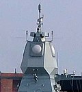 Sea-mobile radar (Active Phased Array Radar on Frigate Hamburg)
 -
 Air-mobile radar (Boeing E-3 Sentry with rotating radar dome)
 -
 Land-mobile radar (TRML-3D Air Surveillance Radar )


Satellites
[edit]
Radiolocation-satellite service (short: RLSS) is – according to Article 1.49 of the International Telecommunication Union's (ITU) Radio Regulations (RR)[2] – defined as «A radiodetermination-satellite service used for the purpose of radiolocation. This (radiocommunication) service may also include the feeder links necessary for its operation.»
The radiolocation-satellite service distinguishes basically
- Earth radio stations
- Feeder links and
- Space radio stations
For example military radar sensors in earth satellites operate in the radiolocation-satellite service n this service.
- Examples of radio stations in the radiolocation-satellite service
-
 "ORS-2" space-based radar
 -
 "NRO Lacrosse" radar satellite
 -
 "ROSAR" radar satellite


| Name | Country | Sensoric |
|---|---|---|
| Lacrosse | USA | military radar (imaging) reconnaissance satellite |
| SAR-Lupe | Germany | military radar (imaging) reconnaissance satellite |
| IGS | Japan | radar reconnaissance and optoelectronic reconnaissance |
| RORSAT | Russian Federation | Radar Ocean Reconnaissance SATellite |
Frequency allocation
[edit]The allocation of radio frequencies is provided according to Article 5 of the ITU Radio Regulations (edition 2012).[3]
In order to improve harmonisation in spectrum utilisation, the majority of service-allocations stipulated in this document were incorporated in national Tables of Frequency Allocations and Utilisations which is within the responsibility of the appropriate national administration. The allocation might be primary, secondary, exclusive, and shared.
- Example of frequency allocation
| Allocation to services | ||
| Region 1 | Region 2 | Region 3 |
24.65-24.75 GHz
|
24.65-24.75
|
24.65-24.75
|
Stations
[edit]Land station
[edit]
Principle
A radiolocation land station is – according to article 1.90 of the International Telecommunication Union's (ITU) ITU Radio Regulations (RR)[4] – defined as "a radio station in radiolocation service not intended to be used while in motion." Each radiolocation station shall be classified by the radiocommunication service in which it operates permanently or temporarily.
In accordance with ITU Radio Regulations (article 1) this type of radio station might be classified as follows:
Radiodetermination station (article 1.86) of the radiodetermination service (article 1.40 )
- Radionavigation mobile station (article 1.87) of the radionavigation service (article 1.42)
- Radionavigation land station (article 1.88) of the radionavigation service
- Radiolocation mobile station (article 1.89) of the radiolocation service (article 1.48)
- Radiolocation land station
- Selection radiolocation land stations
-
 German Radar Wurzburg Riese (FuMG 65)
 -
ALTAIR (ARPA Long-Range Tracking and Instrumentation Radar)
-
 NASA Wallops Flight Facility Radar
 -
 Antenna radar L band TAR Finland
 -
 50 Feet dish Antenna of a 3 kW C band Radar
 -
 Intelligence-gathering phased array radar FPS-108 COBRA DANE
 -
Phased array radar AN/FPQ-16 PARCS
-
 Skyguide radar, Hochwacht in Boppelsen on Lägern (Switzerland)


Mobile station
[edit]Radiolocation mobile station is – according to article 1.89 of the International Telecommunication Union's (ITU) ITU Radio Regulations (RR)[5] – defined as "A radio station in radiolocation service intended to be used while in motion or during halts at unspecified points." Each radiolocation station shall be classified by the radiocommunication service in which it operates permanently or temporarily.
In accordance with ITU Radio Regulations (article 1) this type of radio station might be classified as follows:
Radiodetermination station (article 1.86) of the radiodetermination service (article 1.40 )
- Radionavigation mobile station (article 1.87) of the radionavigation service (article 1.42)
- Radionavigation land station (article 1.88) of the radionavigation service
- Radiolocation mobile station
- Selection radiolocation mobile stations
-
Air Surveillance Radars TRML-3D
-
 High finder radar
 -
 RAAF radar, AN/TPS-77
 -
 German radar sensor LÜR
 -
 MIM-104 Patriot in Japanese service
 -
 Nike Hercules IFC radars LOPAR and the tracking radars (MTR, TTR, TRR) f.l.t.r.
 -
APAR-radar Fregatte Hamburg (F 220)
-
 Weapon control radar
 -
 Sea-based x-band radar underway
 -
 Air borne radar „Lichtenstein SN-2“ in the ME Bf 110G


.jpg)


See also
[edit]References
[edit]- ^ ITU Radio Regulations, Section IV. Radio Stations and Systems – Article 1.48, definition: radiolocation service
- ^ ITU Radio Regulations, Section IV. Radio Stations and Systems – Article 1.49, definition: radiolocation-satellite service
- ^ ITU Radio Regulations, CHAPTER II – Frequencies, ARTICLE 5 Frequency allocations, Section IV – Table of Frequency Allocations
- ^ ITU Radio Regulations, Section IV. Radio Stations and Systems – Article 1.90, definition: radiolocation land station
- ^ ITU Radio Regulations, Section IV. Radio Stations and Systems – Article 1.89, definition: radiolocation mobile station
Further reading
[edit]- Sun, Guolin; Chen, Jie; Guo, Wei; Liu, K. J. R. (July 2005). "Signal Processing Techniques in Network-Aided Positioning: A Survey of State-of-the-Art Positioning Designs" (PDF). IEEE Signal Processing Magazine. 22 (4): 12. Bibcode:2005ISPM...22...12S. CiteSeerX 10.1.1.319.3989. doi:10.1109/MSP.2005.1458273. S2CID 4093889.
- Patwari, N.; Ash, J. N.; Kyperountas, S.; Hero, A. O.; Moses, R. L.; Correal, N. S. (July 2005). "Locating the nodes: cooperative localization in wireless sensor networks" (PDF). IEEE Signal Processing Magazine. 22 (4): 54. Bibcode:2005ISPM...22...54P. doi:10.1109/MSP.2005.1458287. ISSN 1053-5888. S2CID 3259841.
- Hashemi, H. (1993). "The indoor radio propagation channel". Proceedings of the IEEE. 81 (7): 943–968. doi:10.1109/5.231342.
- “Outdoor/Indoor Propagation Modeling for Wireless Communications Systems”, M. Iskander, Z. Yun, and Z. Zhang, IEEE Antennas and Propagation Society, AP-S International Symposium (Digest) v 2 2001. p 150-153
| Authority control databases: National |
|---|
Radiolocation
View on GrokipediaFundamentals
Definition and Basic Principles
Radiolocation is defined as a radiodetermination service for the purpose of determining the position, velocity, and/or other characteristics of objects, or obtaining related information, by means of the propagation properties of radio waves, excluding applications intended to aid the movement of vehicles such as aircraft, ships, or ground vehicles, which fall under radionavigation.[8] This service encompasses both active systems that emit radio signals and passive systems that rely on existing emissions, enabling the detection and localization of targets through signal interactions.[8] At its core, radiolocation relies on the fundamental physics of electromagnetic radio waves, which propagate through free space at the speed of light, approximately m/s. These waves interact with objects via reflection, where they bounce off surfaces altering direction; absorption, in which energy is dissipated into the medium; and diffraction, allowing waves to bend around obstacles, facilitating signal detection beyond direct line-of-sight paths. Such interactions form the basis for inferring object positions by analyzing time delays, phase shifts, or signal strengths. Key challenges in radiolocation stem from environmental and propagation effects that degrade signal accuracy. Multipath propagation occurs when signals arrive via multiple reflected paths, creating echoes that interfere constructively or destructively and cause fading.[9] Non-line-of-sight (NLOS) conditions, arising from obstacles like buildings or terrain, block direct signals and force reliance on weaker diffracted or scattered paths, reducing precision.[9] Additionally, atmospheric factors such as rain, fog, or ionospheric variations can attenuate signals or introduce scintillation, further impacting reliability in diverse operational scenarios.[10] Radiolocation overlaps with radar systems, which typically employ active emission of radio waves to detect reflections from targets, whereas passive radiolocation utilizes ambient radio signals from external sources without dedicated transmission, offering stealth advantages but limited control over illumination.[8]Historical Development
The foundations of radiolocation trace back to the late 19th century, when Heinrich Hertz's experiments in 1888 demonstrated the directional properties of electromagnetic waves, laying the groundwork for radio direction finding (RDF) by showing how radio waves could be transmitted and received in specific directions using simple loop antennas.[11] These discoveries built on James Clerk Maxwell's theoretical predictions of electromagnetic propagation, enabling early practical applications in locating radio sources. In the 1890s, Guglielmo Marconi advanced wireless telegraphy systems that incorporated rudimentary direction-finding techniques, allowing operators to determine the bearing of transmitted signals over distances, which proved essential for maritime communication and navigation.[12] Around the same time, Nikola Tesla proposed in 1900 the use of radio waves to detect distant objects, such as ships, by measuring echoes—a concept that foreshadowed radar technology, though it remained theoretical at the stage. During World War I in the 1910s, RDF evolved rapidly for naval warfare, with systems deployed on ships to locate enemy vessels by triangulating signals from wireless transmitters, marking the first widespread military application of radiolocation for tactical advantage.[13] This momentum continued into the 1930s, as World War II spurred major innovations: the United Kingdom's Chain Home radar network, developed under Robert Watson-Watt, became operational in 1937 and provided early warning of aircraft incursions by detecting echoes from radio pulses at ranges up to 150 miles.[14] Similarly, the United States introduced the SCR-270 mobile radar in 1938, capable of spotting aircraft at 150 miles, which exemplified radiolocation's shift toward active detection systems and underscored its critical role in air defense during the war.[15] Post-World War II, radiolocation expanded into civilian domains with the International Telecommunication Union (ITU) formalizing regulations in its 1947 Atlantic City Radio Regulations, which defined the radiolocation service as involving the use of radio waves to determine the position or direction of objects, with the radionavigation service as a specific application thereof for aiding the movement of ships, vehicles, or aircraft.[16]Techniques and Methods
Time-Based Methods
Time-based methods in radiolocation determine the position, velocity, or other characteristics of an object (which may be a transmitter, receiver, or passive reflector) by measuring the propagation time of radio signals, leveraging the constant speed of light in free space to convert time into distance. These techniques form the foundation of many positioning systems, where the core principle is that the distance between a transmitter and receiver is given by , with as the speed of light (approximately m/s) and as the signal propagation time.[17] Accurate synchronization between clocks at the transmitter and receiver is essential for these methods, as even nanosecond-scale errors can translate to meter-level positioning inaccuracies.[18] The time of arrival (TOA) method measures the absolute time elapsed from signal transmission to reception, enabling direct distance estimation when clocks are precisely synchronized. In practice, TOA systems often employ pseudoranges, which account for unknown clock biases between the transmitter and receiver, allowing position calculation via multilateration from multiple reference points. A prominent example is pulse radar systems used in surveillance, where short bursts of radio waves are transmitted, and the round-trip time of echoes from targets is measured to compute range and position, with the radar's co-located transmitter and receiver providing inherent synchronization.[2][19] This approach achieves positioning accuracies on the order of meters, though it requires consideration of line-of-sight propagation to minimize multipath errors.[17] In contrast, the time difference of arrival (TDOA) method avoids the need for absolute time synchronization by measuring the difference in arrival times of a signal at multiple receivers, each pair defining a hyperbola on which the transmitter must lie. The position is then estimated as the intersection point of these hyperbolas from several receiver pairs, typically solved using nonlinear optimization techniques such as least squares to minimize errors due to noise and propagation delays.[20] The TDOA position estimation can be formulated as minimizing the sum of squared residuals: where is the measured time difference for receiver pair , is the distance from the transmitter to receiver , is the distance to a reference receiver, and is the speed of light; this weighted least squares approach enhances robustness in noisy environments.[20] In cellular networks, TDOA implementations achieve accuracies of 10-100 meters, depending on base station geometry and signal bandwidth.[21] Passive TDOA systems are also used in radiolocation for geolocating radio frequency emitters in surveillance applications, such as electronic intelligence gathering.[22] Implementation challenges in both TOA and TDOA primarily stem from clock synchronization errors, which can introduce biases exceeding the signal propagation time and degrade positioning precision. These errors are commonly mitigated through GPS-assisted timing, where global navigation satellite system receivers provide a common time reference to synchronize local clocks, often augmented by high-stability oscillators like oven-controlled crystal oscillators (OCXOs) for sub-microsecond accuracy.[23] In modern contexts, ultra-wideband (UWB) technology applies TOA for high-precision indoor positioning, exploiting short nanosecond pulses across a wide bandwidth (over 500 MHz) to resolve multipath and achieve centimeter-level accuracy in environments like buildings or warehouses.[24] UWB systems, standardized under IEEE 802.15.4, demonstrate positioning errors below 10 cm in line-of-sight indoor tests, making them suitable for asset tracking and robotics.[25]Angle-Based Methods
Angle-based methods in radiolocation determine the position of an object by measuring the direction, or bearing, from which radio signals arrive or are reflected, typically using the principles of directional antennas or antenna arrays. These techniques rely on the angular information of the signal wavefront to compute bearings, which can then be triangulated from multiple stations to locate the source. Unlike time-based approaches, angle-based methods focus on the geometric direction rather than propagation delays, making them suitable for scenarios where precise angular resolution is needed, such as surveillance and object tracking.[26] A primary angle-based technique is Angle of Arrival (AOA), which employs directional antennas or phased antenna arrays to estimate the incidence angle of an incoming signal. In AOA systems, the bearing angle is derived from phase differences across array elements spaced by distance , using the formula where is the signal wavelength; this phase shift arises because the wavefront reaches each element at slightly different times.[26] Antenna arrays enable electronic beam steering to achieve high angular resolution, often better than 1 degree in modern implementations.[27] Radio Direction Finding (RDF) is a foundational angle-based method that uses loop antennas to identify signal bearings by exploiting the antenna's directional response. A loop antenna produces a null—a sharp minimum in received signal strength—when oriented perpendicular (90 degrees) to the direction of the incoming signal, as it responds primarily to the magnetic component of the electromagnetic wave orthogonal to the loop plane.[27] Traditional RDF systems rotate the loop to find this null for bearing determination, though this introduces a 180-degree ambiguity since the pattern is bidirectional. Modern RDF employs phased array antennas for full 360-degree coverage without mechanical rotation, achieving accuracies below 1 degree through correlative interferometry.[27] The Watson-Watt technique enhances RDF by addressing ambiguities in bearing estimation through amplitude comparison using orthogonal antenna pairs. It deploys two pairs of Adcock antennas—one aligned north-south and the other east-west—to capture signal components in perpendicular directions, then compares their relative signal strengths to compute the angle of arrival.[28] This method integrates with goniometers to resolve the 180-degree ambiguity inherent in single-loop systems by analyzing phase and amplitude ratios, forming cardioid patterns for unambiguous direction indication.[28] Developed in the 1920s for lightning location, it remains influential in high-frequency direction finding due to its simplicity and robustness.[28] Despite their effectiveness, angle-based methods face limitations such as 180-degree bearing ambiguities and susceptibility to multipath propagation, where reflected signals distort the apparent angle of arrival. These ambiguities are often resolved using dual RDF stations for triangulation or sense antennas to compare signal phases.[27] A representative example is the use of RDF in maritime radiolocation for detecting and locating vessels through their transmissions, providing bearing information for collision avoidance and search operations with accuracies generally better than 2 degrees.[27]Hybrid and Advanced Techniques
Multilateration techniques integrate time difference of arrival (TDOA) measurements from at least three receivers with angle of arrival (AOA) data to enable two-dimensional (2D) or three-dimensional (3D) positioning of an object. This hybrid approach addresses limitations of standalone methods by combining hyperbolic positioning from TDOA with directional information from AOA, solving nonlinear equations through iterative trilateration algorithms that estimate the position while minimizing geometric dilution of precision (GDOP), a metric quantifying error amplification due to receiver geometry. In practical implementations, such as wide-area multilateration systems for aircraft surveillance, fusion of TDOA and AOA achieves sub-meter accuracy in outdoor environments by reducing ambiguity in position solutions.[29] Received signal strength indication (RSSI) provides a complementary hybrid method by estimating distance from signal power attenuation, particularly useful in scenarios where time or angle measurements are unreliable. The core model follows the log-distance path loss equation: where is the received power, is the transmit power, is the path loss exponent (typically 2–4 depending on the environment), is the distance, and represents shadowing losses.[30] For indoor applications, RSSI often employs fingerprinting, where pre-collected signal strength databases at known locations are matched against real-time measurements to resolve positions, improving accuracy in multipath-heavy settings over pure propagation modeling.[31] Advanced integrations enhance hybrid techniques through sensor fusion and computational methods for real-time performance. Kalman filtering merges time-of-arrival (TOA), AOA, and RSSI inputs by recursively estimating position states, accounting for noise and dynamics to achieve robust tracking with errors reduced to tens of centimeters in indoor Bluetooth low energy (BLE) systems. In 5G networks, machine learning algorithms mitigate non-line-of-sight (NLOS) errors—common in urban deployments—by predicting propagation corrections from historical data, with post-2020 approaches like online learning frameworks yielding up to 50% accuracy gains in ranging estimates. Emerging hybrid technologies leverage ultra-wideband (UWB) signals combined with TDOA or AOA for centimeter-level precision in Internet of Things (IoT) applications, such as asset tracking, where UWB's high time resolution enables distances accurate to 10 cm even in cluttered spaces. Looking toward 2025 trends, 6G systems incorporate beamforming with integrated sensing and communication (ISAC) for hybrid positioning in ultra-dense environments, using AI-optimized beams to fuse multi-antenna angle data with time measurements, supporting sub-meter localization amid high mobility and interference.[32]Regulatory Framework
International Regulations
The International Telecommunication Union (ITU) Radio Regulations, in their 2024 edition, serve as the primary international treaty governing the use of radio frequencies, including those for radiolocation services, and are adopted through periodic World Radiocommunication Conferences (WRC). Article 1 of the Regulations defines radiodetermination services, which encompass radiolocation as the determination of an object's position or other characteristics by means other than radionavigation using radio wave propagation properties, thereby establishing a framework for interference-free spectrum utilization across member states.[33] Key provisions in the Regulations include protections against harmful interference under Article 15, which prohibits emissions that endanger safety services or seriously degrade radiocommunication, requiring administrations to cooperate in detection, elimination, and resolution through technical measures and goodwill. Coordination procedures for cross-border operations are outlined in Article 9, mandating notifications, agreements, and technical analyses (e.g., No. 9.21) to prevent interference for services like radiolocation, particularly in shared or adjacent bands. The outcomes of WRC-23 in 2023 further enhanced allocations by identifying additional spectrum for International Mobile Telecommunications (IMT), including 5G systems, with specific conditions such as power flux-density limits to protect existing radiolocation services in bands such as the upper 6 GHz band (6.425-7.125 MHz).[33][34] Enforcement of these Regulations occurs at the national level, where administrations issue licenses and monitor compliance to align with ITU provisions; for instance, the U.S. Federal Communications Commission (FCC) incorporates ITU allocations into its Table of Frequency Allocations, ensuring radiolocation operations in designated bands adhere to international coordination requirements.[35] The regulatory framework evolved following the ITU's post-World War II restructuring, with the initial Radio Regulations adopted at the 1947 International Telecommunication Conference in Atlantic City, establishing global spectrum management principles. Subsequent updates occur through WRC cycles every three to four years; notably, WRC-19 initiated studies leading to mmWave band considerations (e.g., 231.5-275 GHz) for high-resolution radiolocation sensing, promoting compatibility with emerging technologies while maintaining protections for primary services.[36]Service Classifications
The radiolocation service, as defined in Article 1.48 of the ITU Radio Regulations, is a radiodetermination service aimed at determining the position, velocity, or other characteristics of an object, or obtaining related information, through the use of radio waves, excluding purposes related to radionavigation.[33] This service encompasses a broad range of applications focused on general location and tracking without the specific intent of facilitating movement or navigation.[33] In distinction, the radionavigation service under Article 1.47 is a radiocommunication service intended for determining the position, velocity, or other characteristics of objects to aid in navigation, obstruction warning, or traffic control.[33] Another related category is the radiodetermination-satellite service per Article 1.49, which employs one or more space stations for radiodetermination, including space-based radiolocation, and may incorporate necessary feeder links.[33] Additionally, the Earth exploration-satellite service (Article 1.50) utilizes radiolocation methods for probing the Earth's surface and atmosphere, often integrated with satellite operations.[33] Within the radiolocation service, systems are categorized as active or passive based on operational mode. Active radiolocation involves stations that transmit radio signals to illuminate targets and receive echoes, as seen in radar applications for object detection. Passive radiolocation, conversely, relies solely on receiving and processing signals emitted by the target or external sources, without transmission from the locating station, enabling stealthier or lower-power operations. Further classification distinguishes fixed radiolocation services, where stations remain at specified locations (per Article 1.84), from mobile radiolocation services, where stations are designed for movement, such as vehicle- or aircraft-mounted systems (per Article 1.85).[33] Practical implementations include industrial uses, such as asset tracking in manufacturing environments to monitor equipment positions via short-range radio techniques. In the amateur context, radiolocation is authorized in select frequency bands on a secondary basis, subject to power restrictions like a maximum mean radiated power of 50 W in certain allocations to minimize interference.[37]Frequency Allocations
The International Telecommunication Union (ITU) manages global radio frequency spectrum through Article 5 of the Radio Regulations, which outlines the Table of Frequency Allocations specifying bands for various services, including radiolocation on a primary or secondary basis.[33] Radiolocation allocations span from VHF to millimeter waves, with primary status in key bands to support radar and positioning systems while accommodating sharing with other services.[33] In the lower microwave range, the 1-3 GHz spectrum includes several primary allocations for radiolocation, such as 1 215-1 300 MHz (co-primary with earth exploration-satellite active and radionavigation-satellite services, with footnote 5.329 requiring protection for aeronautical radionavigation) and 2 700-3 100 MHz (shared with aeronautical radionavigation and meteorological aids under footnotes 5.423 and 5.424).[33] The 8-10 GHz range features extensive primary radiolocation allocations, including 8 025-8 400 MHz (with earth exploration-satellite active, footnote 5.462A), 8 500-9 200 MHz (shared with radionavigation and limited to specific radar types like airborne Doppler aids under footnote 5.470), and 9 300-9 500 MHz (co-primary with earth exploration-satellite active and space research active).[33] For automotive applications, the band 24.05-24.25 GHz is allocated primary to radiolocation worldwide, expanded post-WRC-19 to facilitate short-range sensors, with sharing alongside amateur services (footnote 5.532).[33] Sharing rules are governed by footnotes in the ITU table, emphasizing co-primary status with fixed and mobile services in many bands to minimize interference; for instance, the 1 215-1 240 MHz band mandates protection for aeronautical radionavigation-satellite systems (footnotes 5.329A and 5.330).[33] In millimeter-wave spectrum, the 57-71 GHz range supports primary radiolocation allocations, such as 57-58.2 GHz and 59-64 GHz (shared with fixed, mobile, and inter-satellite services under footnotes 5.547 and 5.559), enabling short-range high-resolution applications following WRC-23 additions.[33][34] Global variations arise due to ITU's three regions: Region 1 (Europe, Africa, Middle East) often imposes stricter coordination for mobile sharing (e.g., 3 300-3 400 MHz includes fixed/mobile except aeronautical mobile, footnotes 5.429-5.429F), while Region 2 (Americas) features amateur service inclusions and U.S.-specific primaries (e.g., 420-450 MHz).[33] Region 3 (Asia-Pacific) aligns closely with Region 1 but varies in power limits, such as reduced emissions to protect adjacent services.[33] Power limits, like those in footnote 5.475 for 9 300-9 500 MHz radars, ensure non-interference with radionavigation.[33] Emerging trends include 2025 considerations for integrated sensing in 6G systems within existing 7-8 GHz radiolocation bands, such as secondary allocations in 6 700-7 075 MHz and primary in 8 025-8 400 MHz, to support submillimeter sensing without new spectrum reallocation.[33][38]| Frequency Band (GHz) | Status | Key Sharing Services | Representative Footnote | Regional Notes |
|---|---|---|---|---|
| 1.215-1.3 | Primary | Radionavigation-satellite, Earth exploration-satellite (active) | 5.329 (aeronautical protection) | Global, with Region 2 coordination |
| 2.7-3.1 | Primary | Aeronautical radionavigation, Meteorological aids | 5.424 (no interference to nav) | Region 2 equal for meteorological radars |
| 8.025-8.4 | Primary | Earth exploration-satellite (active) | 5.462A (sharing rules) | Global |
| 8.5-9.2 | Primary | Radionavigation (airborne Doppler) | 5.470 (limited uses) | Global |
| 24.05-24.25 | Primary | Amateur | 5.532 (post-WRC-19 expansion) | Global |
| 57-64 | Primary | Fixed, Mobile, Inter-satellite | 5.559 (airborne radars) | Global, Region 1 coordination |
| 64-66 | Primary | Inter-satellite, Mobile | 5.562 (restrictions) | Region 2 primary |