Hubbry Logo
19-inch rack19-inch rackMain
Open search
19-inch rack
Community hub
19-inch rack
logo
8 pages, 0 posts
0 subscribers
Be the first to start a discussion here.
19-inch rack
19-inch rack
from Wikipedia

A full-height rack cabinet

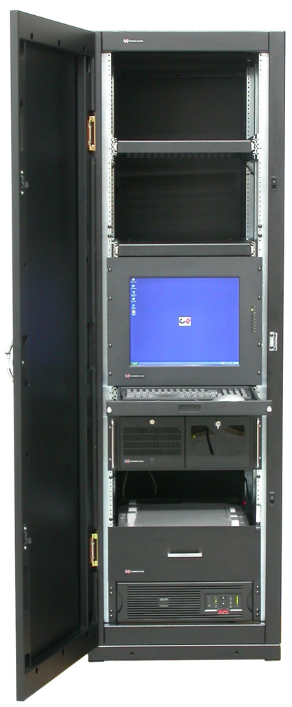
A 19-inch rack is a standardized frame or enclosure for mounting multiple electronic equipment modules. Each module has a front panel that is 19 inches (482.6 mm) wide. The 19 inch dimension includes the edges or ears that protrude from each side of the equipment, allowing the module to be fastened to the rack frame with screws or bolts. Common uses include computer servers, telecommunications equipment and networking hardware, audiovisual production gear, professional audio equipment, and scientific equipment.

Overview and history

[edit]

Equipment designed to be placed in a rack is typically described as rack-mount, rack-mount instrument, a rack-mounted system, a rack-mount chassis, subrack, rack cabinet, rack-mountable, or occasionally simply shelf. The height of the electronic modules is also standardized as multiples of 1.75 inches (44.45 mm) or one rack unit or U (less commonly RU). The industry-standard rack cabinet is 42U tall;[1] however, many data centers have racks taller than this.[2]

The term relay rack appeared first in the world of telephony.[3]

By 1911, the term was also being used in railroad signaling.[4] There is little evidence that the dimensions of these early racks were standardized.

Telephone equipment racks (1923)

The 19-inch rack format with rack-units of 1.75 inches (44.45 mm) was established as a standard by AT&T around 1922 in order to reduce the space required for repeater and termination equipment in a telephone company central office. The earliest repeaters from 1914 were installed in ad hoc fashion on shelves, in wooden boxes and cabinets. Once serial production started, they were built into custom-made racks, one per repeater. But in light of the rapid growth of the toll network, the engineering department of AT&T undertook a systematic redesign, resulting in a family of modular factory-assembled panels all "designed to mount on vertical supports spaced 1912 inches between centers. The height of the different panels will vary,... but... in all cases to be a whole multiple of 1+34 inches."[5]

By 1934, it was an established standard with holes tapped for 12-24 screws with alternating spacings of 1.25 inches (31.75 mm) and 0.5 inches (12.70 mm) [6] The EIA standard was revised again in 1992 to comply with the 1988 public law 100-418, setting the standard U as 15.875 mm (0.625 in) + 15.875 mm (0.625 in) + 12.7 mm (0.500 in), making each U 44.45 millimetres (1.75 in).[7]

The 19-inch rack format has remained constant while the technology that is mounted within it has changed considerably and the set of fields to which racks are applied has greatly expanded. The 19-inch (482.6 mm) standard rack arrangement is widely used throughout the telecommunications, computing, audio, video, entertainment and other industries, though the Western Electric 23-inch standard, with holes on 1-inch (25.4 mm) centers, is still used in legacy ILEC/CLEC facilities.

Nineteen-inch racks in two-post or four-post form hold most equipment in enterprise data centers, ISP facilities, and professionally designed corporate server rooms, although hyperscale computing typically use wider racks.[8][9] They allow for dense hardware configurations without occupying excessive floor space or requiring shelving.

A professional-grade oscilloscope Tektronix 7603 (1970s) for use in electronics and scientific laboratories. Typically for rack-mounted devices, the width of the front panel exceeds the width of the device itself, which provides the overlap zone (including screw holes) with the left and right rack rails.

Nineteen-inch racks are also often used to house professional audio and video equipment, including amplifiers, effects units, interfaces, headphone amplifiers, and even small-scale audio mixers. A third common use for rack-mounted equipment is industrial power, control, and automation hardware.

Typically, a piece of equipment being installed has a front panel height 132 inch (0.031 in; 0.79 mm) less than the allotted number of Us. Thus, a 1U rackmount computer is not 1.750 inches (44.5 mm) tall but is 1.719 inches (43.7 mm) tall. If n is number of rack units, the ideal formula for panel height is h = 1.75n − 0.031 for calculating in inches, and h = 44.45n − 0.794 for calculating in millimeters. This gap allows a bit of room above and below an installed piece of equipment so it may be removed without binding on the adjacent equipment.

Equipment mounting

[edit]
A typical section of 19-inch (482.6 mm) server rack rail, dimensions noted in US inch
A typical section of 19-inch (482.6 mm) server rack rail, dimensions noted in mm (exact)

Fastening

[edit]

Originally, the mounting holes were tapped with a particular screw thread. When rack rails are too thin to tap, rivet nuts or other threaded inserts can be used, and when the particular class of equipment to be mounted is known in advance, some of the holes can be omitted from the mounting rails.[10]

Threaded mounting holes in racks where the equipment is frequently changed are problematic because the threads can be damaged or the mounting screws can break off; both problems render the mounting hole unusable. Tapping large numbers of holes that may never be used is expensive; nonetheless, tapped-hole racks are still in use, generally for hardware that rarely changes. Examples include telephone exchanges, network cabling panels, broadcast studios and some government and military applications.

The tapped-hole rack was first replaced by clearance-hole (Round Hole, Round Unthreaded Holes,[11] and Versa Rail[12]) racks. The holes are large enough to permit a bolt to be freely inserted through without binding, and bolts are fastened in place using cage nuts. In the event of a nut being stripped out or a bolt breaking, the nut can be easily removed and replaced with a new one. Production of clearance-hole racks is less expensive.

The next innovation in rack design has been the square-hole rack. Square-hole racks allow boltless mounting, such that the rack-mount equipment only needs to insert through and hook down into the lip of the square hole. Installation and removal of hardware in a square-hole rack is very easy and boltless, where the weight of the equipment and small retention clips are all that is necessary to hold the equipment in place. Older equipment meant for round-hole or tapped-hole racks can still be used, with the use of cage nuts made for square-hole racks.

Structural support

[edit]

Rack-mountable equipment is traditionally mounted by bolting or clipping its front panel to the rack. Within the IT industry, it is common for network/communications equipment to have multiple mounting positions, including tabletop and wall mounting, so rack-mountable equipment will often feature L-brackets that must be screwed or bolted to the equipment prior to mounting in a 19-inch rack. With the prevalence of 23-inch racks in the Telecoms industry, the same practice is also common, but with equipment having 19-inch and 23-inch brackets available, enabling them to be mounted in existing racks.

A key structural weakness of front-mounted support is the bending stress placed on the mounting brackets of the equipment, and the rack itself. As a result, 4-post racks have become common, featuring a mirrored pair of rear mounting posts. Since the spacing between the front and rear mounting posts may differ between rack vendors and/or the configuration of the rack (some racks may incorporate front and rear rails that may be moved forwards and backward, e.g. APC SX-range racks), it is common for equipment that features 4-post mounting brackets to have an adjustable rear bracket.

Servers and deep pieces of equipment are often mounted using rails that are bolted to the front and rear posts (as above, it is common for such rails to have an adjustable depth), allowing the equipment to be supported by four posts, while also enabling it to be easily installed and removed.

Although there is no standard for the depth of equipment, nor specifying the outer width and depth of the rack enclosure itself (incorporating the structure, doors and panels that contain the mounting rails), there is a tendency for 4-post racks to be 600 mm (23.62 in) or 800 mm (31.50 in) wide, and for them to be 600 mm (23.62 in), 800 mm (31.50 in) or 1,010 mm (39.76 in) deep. This of course varies by manufacturer, the design of the rack and its purpose, but through common constraining factors (such as raised-floor tile dimensions), these dimensions have become quite common. The extra width and depth enables cabling to be routed with ease (also helping to maintain the minimum bend radius for fiber and copper cables) and deeper equipment to be utilized. A common feature in IT racks is mounting positions for zero-U accessories, such as power distribution units (PDUs) and vertical cable managers and ducts, that utilize the space between the rear rails and the side of the rack enclosure.

The strength required of the mounting posts means they are invariably not merely flat strips but actually a wider folded strip arranged around the corner of the rack. The posts are usually made of steel of around 2 mm thickness (the official standard recommends a minimum of 1.9 mm), or of slightly thicker aluminum.

Racks, especially two-post racks, are often secured to the floor or adjacent building structure so as not to fall over. This is usually required by local building codes in seismic zones. According to Telcordia Technologies Generic Requirements document GR-63-CORE, during an earthquake, telecommunications equipment is subjected to motions that can over-stress equipment framework, circuit boards, and connectors. The amount of motion and resulting stress depends on the structural characteristics of the building and framework in which the equipment is contained and the severity of the earthquake. Seismic racks rated according to GR-63, NEBS Requirements: Physical Protection, are available,[13] with Zone 4 representing the most demanding environment.[14][15]

GR-3108, Generic Requirements for Network Equipment in the Outside Plant (OSP), specifies the usable opening of seismic-compliant 19-inch racks.

Rails (slides)

[edit]

Heavy equipment or equipment that is commonly accessed for servicing, for which attaching or detaching at all four corners simultaneously would pose a problem, is often not mounted directly onto the rack but instead is mounted via rails (or slides). A pair of rails is mounted directly onto the rack, and the equipment then slides into the rack along the rails, which support it. When in place, the equipment may also then be bolted to the rack. The rails may also be able to fully support the equipment in a position where it has been slid clear of the rack; this is useful for inspection or maintenance of equipment which will then be slid back into the rack.[16] Some rack slides even include a tilt mechanism allowing easy access to the top or bottom of rack-mounted equipment when it is fully extended from the rack.[17]

Slides or rails for computers and other data processing equipment such as disk arrays or routers often need to be purchased directly from the equipment manufacturer, as there is no standardization on such equipment's thickness (measurement from the side of the rack to the equipment) or means for mounting to the rail.

A rails kit may include a cable management arm (CMA), which folds the cables attached to the server and allows them to expand neatly when the server is slid out, without being disconnected.

Computer mounting

[edit]
Example of 19-inch computer rack with servers

Computer servers designed for rack-mounting can include a number of extra features to make the server easy to use in the rack:

  • The sliding rails can lock in various extended positions to prevent the equipment from moving when extended out from the rack for service.
  • The server itself might have locking pins on the sides that just drop into slots on the extended rail assembly, in a manner similar to a removable kitchen drawer. This permits very easy server installation and removal since there is no need for the server to be held in midair while someone fastens each rail to the sides of the server with screws.
  • Some manufacturers of rack-mount hardware include a folding cable tray behind the server, so that the cables are held into a neat and tidy folded channel when inside the rack, but can unfold out into a long strip when pulled out of the rack, allowing the server to continue to be plugged in and operating normally even while fully extended and hanging in mid-air in front of the rack. This piece of equipment thus simplifies maintenance but at the cost of providing a restriction to airflow.
  • Rack-optimized servers might duplicate indicator lights on the front and rear of the rack to help identify a machine needing attention or provide separate identify LED indicators on both sides of the server (which can be turned on in software or by pushing an associated button). Since some configurations permit over fifty 1U servers in a single rack, this provides a simple method to determine exactly which machine is having a problem when at the rear of the rack.
  • A handle may be provided at the rear of the server rails, to help pull or push the server without having to pull on the cables.

When there is a large number of computers in a single rack, it is impractical for each one to have its own separate keyboard, mouse, and monitor. Instead, a KVM switch or LOM software is used to share a single keyboard/video/mouse set amongst many different computers.

Since the mounting hole arrangement is vertically symmetric, it is possible to mount rack-mountable equipment upside-down. However, not all equipment is suitable for this type of mounting. For instance, most optical disc players will not work upside-down because the driving motor mechanism does not grip the disc.

Rack types

[edit]

19-inch server racks can vary in quality. A standard 19-inch server rack cabinet is typically 42u in height, 600 millimetres (24 in) wide, and 36 inches (914.40 mm) deep.[18] This comprises a volume of 974 L, or just under a cubic meter. Newer server rack cabinets come with adjustable mounting rails allowing the user to place the rails at a shorter depth if needed. There are a multitude of specialty server racks including soundproof server racks, air-conditioned server racks, NEMA-rated, seismic-rated, open frame, narrow, and even miniature 19-inch racks for smaller applications. Cabinets are generally sized to be no wider than the standard 24-inch-wide (610 mm) floor tiles used in most data centers.

Racks carrying telecom equipment like routers and switches often have extra width to accommodate the many cables on the sides.

Four-post cabinet racks

[edit]

Four-post racks allow for mounting rails to support the equipment at the front and rear. These racks may be open in construction without sides or doors or may be enclosed by front and/or rear doors, side panels, and tops.[19] Most data centers use four-post racks.

Two-post relay racks

[edit]

Two-post racks provide two vertical posts. These posts are typically heavy gauge metal or extruded aluminum. A top bar and wide foot connect the posts and allow the rack to be securely attached to the floor and/or roof for seismic safety. Equipment can be mounted either close to its center of gravity (to minimize load on its front panel), or via the equipment's front panel holes.[20] The Relay Racks name comes from early two-post racks which housed telephone relay and switching equipment. Two-post racks are most often used for telecommunication installations.

ATA road case racks

[edit]
Rack-mounted audio power amplifiers of a sound reinforcement system. The racks each have large heavy-duty rollers. This is typical for relatively impromptu venues such as open-air concerts.

19-inch equipment that needs to be moved often or protected from harsh treatment can be housed in a road case approved by the Air Transport Association of America (ATA), sometimes also referred to as a flight case. Road cases typically have plywood sides laminated with polyvinyl chloride (PVC), extruded aluminum edges, steel corners, handles, and latches. Larger cases typically have wheels for easy transport. Road case racks come in different heights based on the 1U standard and different depths. Non-isolated cases simply mount 19-inch mounting posts inside the case. To protect equipment from shock and vibration, road rack cases use an inner and outer case. These cases can be isolated by thick layers of foam or may use spring-loaded shock mounting. Touring musicians, theatrical productions and sound and light companies use road case racks.[21]

Rack strips used for road cases comes with 2 types: single angle and double angle. Double angle rack strips offer better structural strength and an additional mounting face for cable management or additional support for heavy equipment.[22]

Fiberglass-reinforced plastic case racks

[edit]

In 1965, a durable fiber-reinforced plastic 19-inch rackmount case was patented by ECS Composites and became widely used in military and commercial applications for electronic deployment and operation.[citation needed] Rackmount cases are also constructed of thermo-stamped composite, carbon fiber, and DuPont's Kevlar for military and commercial uses.[citation needed]

Polyethylene molded case racks

[edit]

Portable rack cases using a rotary-molded polyethylene outer shell are a lower-cost alternative to the more durable ATA-approved case. These cases are marketed to musicians and entertainers for equipment not subject to frequent transportation and rough handling. The polyethylene shell is not fiberglass reinforced and is not rigid. The shape of small cases is maintained by the rack rails and the cover seal extrusions alone. Larger cases are further reinforced with additional plywood or sheet metal. The outer shell is frequently embossed in a self-mating pattern to combat the tendency for stacked cases to deform slightly creating a slope that encourages the upper case to slide off. The cases typically use extruded aluminum bands at the ends of the body with tongue-and-groove mating to like bands for the covers. End covers are typically secured with either a simple draw latch or a rotary cam butterfly latch, named for the shape of the twist handle.

Cooling

[edit]

There is no standard for airflow and cooling of rack-mounted equipment. A variety of airflow patterns can be found, including front intakes and rear exhausts, as well as side intakes and exhausts. Low-wattage devices may not employ active cooling, but use only passive thermal radiation and convection to dissipate heat.

For rack-mounted computer servers, devices generally intake air on the front and exhaust on the rear. This prevents circular airflows where hot exhaust air is recirculated through an adjacent device and causes overheating.

Although open-frame racks are the least expensive, they also expose air-cooled equipment to dust, lint, and other environmental contamination. An enclosed sealed cabinet with forced air fans permits air filtration to protect equipment from dust.

Large server rooms will often group rack cabinets together so that racks on both sides of an aisle are either front-facing or rear-facing, which simplifies cooling by supplying cool air to the front of the racks and collecting hot air from the rear of the racks. These aisles may themselves be enclosed into a cold air containment tunnel so that cooling air does not travel to other parts of the building where it is not needed or mixes with hot air, making it less efficient. Raised or false floor cooling in server rooms can serve a similar purpose; they permit cooling airflow to equipment through the underfloor space to the underside of enclosed rack cabinets.[23]

A difficulty with forced air fan cooling in rack equipment is that fans can fail due to age or dust. The fans themselves can be difficult to replace. In the case of network equipment, it may be necessary to unplug 50 or more cables from the device, remove the device from the rack, and then disassemble the device chassis to replace the fans.

However, some rack equipment has been designed to make fan replacement easy, using quick-change fan trays that can be accessed without removing the cabling or the device from the rack, and in some cases without turning off the device so that operation is uninterrupted during replacement.

Specifications

[edit]
Computer keyboard and monitor mounted on a sliding tray in a rack

The formal standards for a 19-inch (482.6 mm) rack are available from the following:

  • Electronic Industries Alliance EIA-310-D, Cabinets, Racks, Panels, and Associated Equipment, dated September 1992. (Latest Standard Now REV E 1996)
  • Consumer Electronics Association CEA-310-E design requirements for Cabinets, Panels, Racks and Subracks., dated December 14, 2005
  • International Electrotechnical Commission - Multiple documents are available in French and English versions.
    • IEC 60297 Mechanical structures for electronic equipment - Dimensions of mechanical structures of the 482,6 mm (19 in) series
      • IEC 60297-1 Replaced by IEC 60297-3-100
      • IEC 60297-2 Replaced by IEC 60297-3-100
      • IEC 60297-3-100 Part 3-100: Basic dimensions of front panels, subracks, chassis, racks and cabinets
      • IEC 60297-3-101 Part 3-101: Subracks and associated plug-in units
      • IEC 60297-3-102 Part 3-102: Injector/extractor handle
      • IEC 60297-3-103 Part 3-103: Keying and alignment pin
      • IEC 60297-3-104 Part 3-104: Connector dependent interface dimensions of subracks and plug-in units
      • IEC 60297-3-105 Part 3-105: Dimensions and design aspects for 1U chassis
      • IEC 60297-4 Replaced by IEC 60297-3-102
      • IEC 60297-5 Multiple documents, -100, 101, 102, ... 107, replaced by IEC 60297-3-101
  • Deutsches Institut für Normung DIN 41494 - Multiple documents in German but some documents are available in English.
    • DIN 41494 Equipment practices for electronic equipment; mechanical structures of the 482,6 mm (19 inch) series
      • DIN 41494-7 Dimensions of cabinets and suites of racks.
      • DIN 41494-8 Components on front panels; mounting conditions, dimensions
      • DIN IEC 60297-3-100 (see above in IEC section)

A rack's mounting fixture consists of two parallel metal strips (also referred to as posts or panel mounts) standing vertically. The posts are each 0.625 inches (15.88 mm) wide, and are separated by a gap of 17.75 inches (450.85 mm), giving an overall rack width of 19 inches (482.60 mm). The posts have holes in them at regular intervals, with both posts matching, so that each hole is part of a horizontal pair with a center-to-center distance of 18.28–18.34 inches (464.2–465.8 mm).[24]

The holes in the posts are arranged vertically in repeating sets of three, with center-to-center separations of 0.5, 0.625, 0.625 inches (12.70, 15.88, 15.88 mm). The hole pattern thus repeats every 1.75 inches (44.45 mm).

Holes so arranged can either be tapped (usually 10-32 UNF thread, or, less often, 6mm metric) or have square holes for cage nuts.

Rack unit

[edit]

Racks are vertically divided into regions, 44.45 millimetres (1.75 in) in height. Each region has three complete hole pairs on each side. The holes are centered at 6.35 millimetres (0.25 in), 22.25 millimetres (0.88 in), and 38.1 millimetres (1.50 in) from the top or bottom of the region. Such a region is commonly known as a U, for unit, RU for rack unit or, in German, HE, for Höheneinheit. Heights within racks are measured by this unit. Rack-mountable equipment is usually designed to occupy some integer number of U. For example, an oscilloscope might be 4U high. Rack-mountable computers and servers are mostly between 1U and 4U high. A blade server enclosure might require 10U.

Occasionally, one may see fractional U devices such as a 1.5U server or devices that are just 22.5 or 15 cm in width, allowing for 2 or 3 such devices to be installed side by side, but these are much less common.

The height of a rack can vary from a few inches, such as in a broadcast console, to a floor-mounted rack whose interior is 45 rack units (200.2 centimetres or 78.82 inches) high. 42U is a common configuration. Many wall-mounted enclosures for industrial equipment use 19-inch racks.

[edit]

10-inch rack

[edit]
Comparison between 10-inch and 19-inch rack dimensions

Some telecommunications and networking equipment is available in a narrower 10-inch format with the same unit height as a standard 19-inch rack. This standard is also gaining in popularity with hobbyists with limited space at their disposal.[25]

11-foot frame

[edit]

Frames for holding rotary-dial telephone equipment such as step-by-step telephone switches were generally 11 feet 6 inches (3.51 m) high. A series of studies led to the adoption of frames 7 feet (2.1 m) high, with modular widths in multiples of 1 foot 1 inch (0.33 m)—most often 2 feet 2 inches (0.66 m) wide.[26]

ETSI rack

[edit]
Comparison between 19-inch and ETSI rack dimensions

The ETSI rack is defined by the European Telecommunications Standards Institute (ETS 300 119). The distance of the right edge of the right mounting rail to the left edge of the left mounting rail is 535 millimetres (21.1 in). As 535 mm is very close to 21 inches, these racks are sometimes called 21-inch racks. The gap between the posts is 500 millimetres (19.69 in). As 19-inch equipment has a maximum width of 17+14 inches (438.15 mm), they can easily be mounted in an ETSI rack by means of an ETSI bracket or adapter plate.

In contrast to the 19-inch standards, ETSI also defined the size of the rack enclosure: the four allowed widths are 150, 300, 600, 900 millimetres (5.9, 11.8, 23.6, 35.4 in) and two allowed depths are 300 and 600 millimetres (12 and 24 in). Hole spacing is 25 millimetres (0.98 in).

23-inch rack

[edit]
The 1948 original Manchester Baby and the 1998 working replica (pictured) were mounted on 23-inch racking.[27]

A 23-inch (580 mm) rack is used for housing telephone (primarily), computer, audio and other equipment – although it is less common than the 19-inch rack. The size denotes the width of the faceplate for the installed equipment. The rack unit is a measure of vertical spacing and is common to both the 19 and 23-inch racks.

Hole spacing is either on 1-inch (25 mm) centers (Western Electric standard), or the same as for 19-inch (482.6 mm) racks (0.625 in or 15.9 mm spacing).

Open Rack

[edit]

Open Rack is a mounting system designed by Facebook's Open Compute Project that has the same outside dimensions as typical 19-inch racks (e.g. 600 mm width), but supports wider equipment modules of 547 millimetres (21.5 in).[28]

OpenVPX

[edit]

OpenVPX is an industry standard for modules that can be installed in chassis in defense applications. The modules can provide a variety of functions, similarly to equipment in a rack.[29]

Eurorack

[edit]

Eurorack is a standard generally used in electronic music production to install components of a modular synthesizer, an electronic music instrument. This is achieved with a rack mounting system specific to the standard.[30]

Eurocard

[edit]

Eurocard is an IEEE standard format for printed circuit board (PCB) cards that can be plugged together into a standard chassis which, in turn, can be mounted in a 19-inch rack. The chassis consists of a series of slotted card guides on the top and bottom, into which the cards are slid so they stand on end, like books on a shelf. At the spine of each card is one or more connectors which plug into mating connectors on a backplane that closes the rear of the chassis.[31][32][33] Several standards such as VMEbus (Versa Module Eurocard[34] bus), STEbus,[35] PCI eXtensions for Instrumentation, openGear[36] and others were developed, which share goals with Eurocard.

[edit]

See also

[edit]

References

[edit]
[edit]
Revisions and contributorsEdit on WikipediaRead on Wikipedia
from Grokipedia
A 19-inch rack is a standardized frame or enclosure used for mounting multiple modules of electronic, electrical, and mechanical equipment, with each module featuring a exactly 19 inches (482.6 mm) wide. This design ensures compatibility and efficient organization of components such as servers, networking gear, and power supplies within a compact vertical space. The standard governing 19-inch racks is EIA-310-D, established by the (now maintained by the Electronic Components Industry Association following EIA's dissolution in 2011) to unify dimensions, mounting hole patterns, and structural requirements across manufacturers. Originating from early 20th-century telephone infrastructure, the format was developed by around 1922 to minimize space for relay repeaters and distribution frames in central offices. By the mid-1930s, it had evolved into a broader industry norm for relay racks, with formal through EIA-310 in the 1960s amid growing demands for modular electronics in and industrial applications. Key specifications include the , a modular height of 1.75 inches (44.45 mm) that defines vertical stacking increments for equipment. Mounting occurs on paired vertical rails with square or tapped holes spaced in a repeating pattern of 0.5 inches (12.7 mm), 0.625 inches (15.9 mm), and 0.625 inches (15.9 mm) within each U, while the horizontal distance between rail centers measures 18.312 inches (465.1 mm). These racks, often enclosed in cabinets up to 42U or more in height, support static weights typically up to 2,000–3,000 pounds (900–1,360 kg) and are ventilated for thermal management in high-density setups. Widely adopted in telecommunications for , data centers for , audio-visual systems for broadcast equipment, and laboratory settings for , 19-inch racks facilitate , , and easy access for maintenance. Equivalent international standards, such as IEC 60297 and DIN 41494, align closely with EIA-310 to promote global . As of late 2025, the core 19-inch format endures unchanged, though adaptations for high-density AI servers and edge computing now emphasize enhanced power delivery, liquid cooling, and modular designs to handle increased computational loads while maintaining compatibility. For example, Supermicro announced liquid-cooled 4U systems for NVIDIA HGX B300 Blackwell GPUs designed for standard 19-inch racks, supporting up to 64 GPUs per rack with direct liquid cooling capturing up to 98% of system heat.

Introduction

Definition and Purpose

A 19-inch rack is a standardized metal frame or designed to mount multiple electronic modules side-by-side, with the "19-inch" referring to the horizontal width of the mounting faces (482.6 exactly). This standardization, governed by the EIA-310 specification from the , ensures consistent mounting holes and spacing for equipment front panels. The primary purpose of the 19-inch rack is to enable modular installation, , and of equipment in industries requiring dense packing, such as , , and audiovisual systems. It facilitates maintenance by allowing easy access and replacement of individual units without disrupting the entire system. This design supports efficient organization of components in shared environments, promoting reliability and ease of upgrades. Key benefits of the 19-inch rack include space efficiency through compact arrangement, that ensures compatibility across different manufacturers' equipment, and the ability to support vertical stacking for maximizing floor space utilization. The origin of the 19-inch width derives from early panels, where it accommodated multiple plug-in units without excessive gaps, a practice established around 1922 by to optimize space in telephone exchanges.

Historical Development

The origins of the 19-inch rack trace back to the early , when the concept evolved within the , where —a subsidiary of —developed racks specifically for equipment to streamline the installation of relays and switches in central offices. A pivotal milestone occurred in 1922, when formalized the 19-inch width as the standard for mounting holes on vertical rails, aiming to minimize space usage and enhance efficiency in crowded telephone facilities. This decision optimized equipment density compared to earlier, wider formats and quickly became integral to the Bell System's infrastructure. Following , amid the postwar electronics boom, the standard gained broader adoption beyond telecom, extending to computing hardware and military electronics to support rapid technological scaling. The (EIA) played a key role in this expansion by publishing the inaugural EIA-310 standard (initially as RS-310) in 1965, which defined the 19-inch width, 1.75-inch rack units, and mounting hole patterns for interoperability across industries. This standard was later revised, with EIA-310-D issued in 1992. In the 1970s and 1980s, advanced the rack's integration into more robust environments by developing the Network Equipment-Building System (NEBS), a set of criteria for equipment reliability in facilities, which incorporated 19-inch racks for data centers and network operations. This era marked the rack's transition into computing applications, driven by the rise of mainframes and early servers. As of 2025, the core 19-inch format endures unchanged, though adaptations for high-density AI servers and now emphasize enhanced power delivery, liquid cooling, and modular designs to handle increased computational loads while maintaining compatibility.

Technical Specifications

Standard Dimensions

The 19-inch rack standard specifies a mounting face width of exactly 19 inches (482.6 mm) between the vertical rails, enabling uniform equipment installation across compatible systems. For enclosed cabinets, the overall external width typically measures 23 to 24 inches (584 to 610 mm) to include side panels, doors, and structural reinforcements while maintaining the internal mounting dimension. Rack height has no fixed limit and scales vertically using rack units for flexibility in accommodating varying equipment volumes. Depths are not rigidly standardized but commonly range from 600 mm (24 inches) to 1200 mm (47 inches), with 800 mm (31.5 inches) frequently used in setups to balance space efficiency and . Vertical mounting holes along the rails follow a repeating pattern of 0.5-inch (12.7 mm), 0.625-inch (15.9 mm), and 0.625-inch (15.9 mm) spacings between centers within each , to support precise equipment alignment, typically featuring either approximately 0.375-inch (9.5 mm) square holes for cage nuts or threaded #10-32 UNC holes for direct screwing. Horizontal mounting ears on rack-mounted devices generally include 4 to 6 holes per side, spaced to engage the rail holes securely and distribute load evenly. The EIA-310 standard establishes non-cumulative tolerances of ±0.015 inches (0.38 mm) between any two hole positions to ensure and prevent misalignment issues across manufacturers. Rack frames are typically constructed from 14- to 16-gauge for durability and rigidity, supporting weight capacities up to 2000 pounds (907 kg) per column in fully assembled configurations.

Rack Unit

The rack unit (abbreviated as U or RU) is the standard unit of vertical used in 19-inch racks to facilitate the modular stacking of . One rack unit equals 1.75 inches (44.45 mm) in height, a dimension originally derived from the standardized heights of early panels to optimize space for repeaters and termination . This measurement system allows for precise calculation of total rack height by multiplying the number of rack units by 1.75 inches; for instance, a 42U rack measures 73.5 inches (1,867 mm) in usable vertical space, excluding any base or top clearance required for installation and ventilation. The standard was first established by around 1922 and later formalized in the EIA-310-D specification in 1992, ensuring compatibility across , , and audio-visual applications. In practice, equipment such as servers and storage devices is designed to occupy an integer number of rack units to maintain uniform alignment and airflow within the rack; common examples include 1U servers for high-density and 2U units for storage arrays, with fractional units generally avoided to prevent misalignment during installation. Full-height racks typically provide 42U or 45U of space to accommodate extensive server deployments in data centers, while half-height options around 24U are common for wall-mounted setups in smaller environments. As of 2025, compact micro-racks as small as 6U have emerged for applications, enabling efficient deployment of networked devices in distributed locations with limited space.

Mounting Standards

The primary standard governing the mounting of equipment in 19-inch racks is EIA-310-E, published by the Electronic Components Industry Association (ECIA), which specifies the overall design requirements for cabinets, panels, racks, and subracks, including hole patterns, thread types, and load distribution guidelines. This standard ensures by defining the mounting interface for electronic equipment, with the front panel width fixed at 19 inches (482.6 mm) to accommodate standardized module mounting. Hole configurations in EIA-310-E compliant racks feature mounting rails with holes spaced in repeating patterns every 1 (1U, or 1.75 inches/44.45 mm vertically), typically in groups of three holes for securing equipment ears. Common thread types include #12-24 UNC in North American applications for direct screw mounting and M6 metric threads for international use, while universal square holes (approximately 9.5 mm x 9.5 mm) allow for the installation of cage nuts to adapt to various fastener sizes. Alignment pins may be incorporated optionally between hole groups to aid in precise equipment insertion and prevent lateral shifting during installation. The IEC 60297 standard aligns with EIA-310 in hole spacing (15.9 mm between mounting holes) and dimensions for global compatibility. Compliance with EIA-310-E requires testing for structural integrity, including static load capacities often rated up to 1,000–2,500 pounds depending on , with considerations for operational stresses. Seismic performance is evaluated to Zone 4 standards (the highest risk category), involving shake-table simulations to ensure racks withstand earthquakes without failure, as outlined in related criteria like NEBS GR-63-CORE. Grounding provisions are mandatory, typically via integrated lugs or kits using 1/4-20 hardware to connect equipment to the rack frame, facilitating electrical safety and reduction. Internationally, ANSI/EIA-310-E serves as the benchmark for rack mounting interfaces, while the equivalent IEC 60297 standard (specifically IEC 60297-3-100 for subracks and modules) is adopted and aligns closely to promote global compatibility in dimensions and mounting patterns. In applications, NEBS Level 3 compliance extends these standards by incorporating environmental , such as vibration, thermal extremes, and seismic events, to ensure reliability in carrier-grade deployments. As of 2025, while high-density networking demands (e.g., 400G+ transceivers) have prompted enhancements in rack power and cooling specifications, the core mounting standards under EIA-310-E and IEC 60297 remain unchanged since the , focusing instead on supplementary guidelines for equipment density without altering hole patterns or load interfaces.

Mounting and Installation

Fastening Methods

Equipment in 19-inch racks is primarily secured to the front mounting rails using screw fastening through the equipment's front ears or flanges. These ears align with the rack's vertical rails, which feature either threaded round holes or unthreaded square holes compliant with the EIA-310 standard. For threaded round holes, typically spaced according to the 5/8-5/8-1/2 inch pattern, 10-32 UNF screws are standard in North American applications, while M6 metric screws (ISO fine thread) are prevalent in international and European setups. In racks with square holes (9.5 or 0.374 inch side length), provide the necessary threading for attachment. A comprises a spring-steel that clips into the square and a threaded captured within it, allowing the ears to be fastened securely once the is installed from the rear of the rail. This method supports adjustability, as can be positioned at any square without permanent alteration to the rail. Installation involves compressing the 's wings with a tool or to insert it, ensuring the 's threading faces the front for engagement. Tool-less fastening options, such as snap-in plastic retainers or quarter-turn fasteners, offer alternatives to traditional screws and cage nuts, enabling rapid installation without tools. These are particularly useful in high-density data centers for minimizing during equipment swaps; for example, spring-loaded snap-in buttons insert directly into square holes and lock via friction, while quarter-turn cam locks provide a twist-to-secure mechanism compatible with round or square holes. Load distribution is critical for safe mounting, with front-only attachment via ears recommended for equipment under 35 pounds (15.9 kg) per to avoid stress on the flanges and potential rack tipping. Heavier units exceeding this threshold require additional rear support, such as brackets or shelves, to distribute weight evenly and comply with structural integrity guidelines. Best practices for fastening emphasize proper application to ensure secure hold without damaging components: 10-32 screws should be torqued to approximately 25-31 inch-pounds (2.8-3.5 N·m), while M6 screws use 20-25 inch-pounds (2.3-2.8 N·m), often verified with a torque driver. or metal washers are advised under screw heads to prevent on equipment flanges and distribute compressive forces evenly across the ears. Over-tightening must be avoided to prevent deformation of the thin rails (typically 14-16 gauge ) or stripping of threads. To address vibration in environments like or audio applications, split lock washers are incorporated under the screw heads to maintain tension and resist loosening over time. As of 2025, quick-release levers and cam-action fasteners have seen increased adoption for hot-swappable components, such as power supplies and network modules, allowing one-handed operation for faster service without full disassembly.

Rail Systems

Rail systems in 19-inch racks primarily consist of two types: static rails, which provide fixed positioning for without extension capability, and telescoping rails, often featuring ball-bearing slides for smooth extension and retraction. Static rails are simpler and used for lighter or less frequently accessed , securing devices directly to the rack posts without movement. Telescoping rails, on the other hand, use multiple nested sections with ball-bearing mechanisms to allow full or partial extension of the mounted , facilitating and service without removal. These ball-bearing slides are typically rated for dynamic loads between 50 and 300 pounds, depending on the model and material, ensuring reliable support for heavier servers during extension. Installation of rail systems involves adjusting the rails to match the rack's depth, commonly ranging from 24 to 36 inches, to accommodate varying equipment dimensions. Rails are mounted to the front and rear posts of the rack using brackets or clips that align precisely with the 1U (1.75-inch) vertical spacing defined in EIA-310 standards for universal 19-inch compatibility. Profiles of these rails often include L-shaped designs for basic support or Z-shaped configurations for enhanced stability and cable routing, with extension lengths reaching up to 30 inches to provide adequate access for servicing internal components. These systems are installed in conjunction with fastening methods to ensure a secure hold during operation. In applications, rail systems are essential for mounting servers deeper than 20 inches, where fixed positioning alone would hinder access to rear connections or internals. Telescoping rails support quick-disconnect mechanisms that enable hot-swappable components, minimizing downtime in data centers. As of 2025, many advanced rail designs integrate features, such as built-in trays or clips, to organize high-speed cabling and reduce signal interference in dense networking environments. Maintenance of rail systems focuses on preserving the functionality of ball-bearing slides through regular at intervals recommended by manufacturers, typically every 6-12 months or after 10,000 extension cycles, to prevent wear and ensure smooth operation. Load ratings must account for in dynamic use, where the effective capacity is reduced to approximately 80% of the static rating to avoid deformation or failure under repeated extension and .

Structural Supports

Structural supports in 19-inch racks are essential for maintaining frame integrity under varying loads, preventing deformation or during operation or environmental stresses. Key components include cross-bracing, which connects vertical posts diagonally or horizontally to enhance torsional rigidity and resist lateral forces; base plates, which distribute floor loads and provide mounting points for anchoring; and top caps, which secure the upper frame while allowing cable access and adding overhead stability. In enclosed cabinet variants, side panels further bolster lateral strength by forming a rigid that minimizes sway and vibration transmission. Load distribution varies by design, with four-post racks offering superior even weight sharing across all posts, enabling static capacities up to 3000 pounds for heavy-duty applications like servers. In contrast, two-post racks concentrate loads on front supports, necessitating rear tie-offs to walls or floors for enhanced stability and to prevent tipping under dynamic conditions. These configurations ensure safe equipment mounting while integrating briefly with rail systems for overall support. Seismic reinforcements are critical in high-risk areas, featuring base anchoring via J-bolts that embed into floors for firm attachment, combined with sway bracing that limits horizontal movement during earthquakes. These elements comply with UBC Zone 4 standards, which specify design for severe ground accelerations up to 0.4g, ensuring racks remain upright and equipment protected in regions like parts of . For depth accommodations, open-frame racks employ beams that project rearward from front posts to support extended equipment without full-depth framing, optimizing in shallow installations. Adjustable leveling feet, typically threaded for 1-2 inches of vertical adjustment, compensate for uneven floors by stabilizing the base and preventing wobble, which is vital in older buildings or raised floors. As of 2025, advancements in dense AI deployments have introduced integrated cable trays and power distribution units (PDUs) mounted within rack structures to counterbalance rear-heavy loads from high-wattage GPUs and cooling systems, maintaining center-of-gravity stability in racks exceeding 2000 pounds. These features reduce cabling overhang and distribute ancillary weights evenly, supporting power densities up to 60 kW per rack without compromising structural .

Rack Variants

Enclosed Cabinets

Enclosed cabinets are fully enclosed variants of 19-inch racks, typically featuring a four-post frame that provides complete structural enclosure for mounted equipment, offering superior protection against unauthorized access, environmental hazards, and physical damage. These cabinets commonly stand at full height, accommodating up to rack units (U), with depths ranging from 600 mm to 1200 mm to suit various installation spaces and equipment sizes. The design includes lockable front doors, often made of for visibility and ventilation, paired with solid metal rear doors for added security, while removable side panels allow for internal access during maintenance without full disassembly. Key features of enclosed cabinets include integrated grounding systems to ensure electrical safety and compliance with standards like IEC 60297, as well as cable entry glands that facilitate organized wiring while maintaining the enclosure's integrity against and ingress. Many models achieve IP55 ratings or higher, protecting against accumulation and low-pressure jets, making them suitable for industrial or outdoor-adjacent environments. Depths are standardized to align with 19-inch equipment widths, with adjustable mounting rails supporting payloads up to 1200 kg through reinforced flooring and robust steel construction. These cabinets provide significant advantages in through keyed locks, optional biometric access controls, and tamper-evident seals, which are essential in high-value installations. They also offer noise dampening capabilities, reducing operational sounds to below 50 dB for office or deployments, enhancing user comfort without compromising airflow. As of 2025, advanced models incorporate IoT sensors for real-time monitoring of temperature, humidity, and access events, enabling and integration with systems. In common applications, enclosed cabinets are widely used in data centers for colocation services, where they secure servers and networking gear while supporting high-density configurations. Their load-bearing capacities, often reinforced with additional bracing, allow for stacking heavy equipment like blade servers or storage arrays, ensuring stability in seismic-prone areas when anchored properly. Wall-mount enclosed cabinets represent a compact variant, typically spanning 12 to 24U, designed for space-constrained environments such as branch offices or retail server rooms. These units maintain the full benefits but with shallower depths (around 600 mm) and swing-out frames for easier access, supporting loads up to 75 kg while adhering to the same 19-inch mounting standards.

Open Frame Racks

Open frame racks consist of two- or four-post ladder-style frames lacking side panels or doors, emphasizing and for mounting 19-inch . These structures typically feature heights of 42U to 48U, equivalent to 73.5 to 84 inches, allowing accommodation of multiple rack units while fitting standard dimensions. External widths range from 19 to 23 inches, providing sufficient space for equipment ears without excess footprint. Key features include adjustable mounting rails positioned at both front and rear positions, enabling customizable depth from approximately 20 to 40 inches to suit various device sizes. These racks support high load capacities, often rated between 1500 and 2500 pounds statically, ensuring stability for dense configurations. Additionally, they facilitate easy expansion through modular stacking of sections, promoting in installations. The primary advantages of open frame racks lie in their superior natural ventilation, which dissipates heat effectively around equipment without obstructions, making them suitable for high-thermal-load applications. They offer a cost-effective alternative for laboratory and testing environments due to simpler construction and lower material costs compared to enclosed variants. As of 2025, projections indicate that 21-inch open rack variants are gaining traction for AI applications in hyperscale data centers, complementing traditional 19-inch designs. A specialized variant, the relay rack, employs a traditional two-post configuration optimized for patching and distribution. These racks often incorporate perforated uprights to enhance and routing, supporting efficient organization of patch panels and wiring in telecom closets. However, open frame racks provide reduced , exposing equipment to unauthorized access, and necessitate additional electromagnetic interference (EMI) shielding measures for sensitive deployments.

Portable Racks

Portable racks are specialized 19-inch rackmount enclosures designed for mobility and rugged transport, often encased in flight-ready cases to protect sensitive electronics during shipping, handling, and field operations. These units typically range from 6 to 20 rack units (U) in height to accommodate compact to mid-sized equipment setups, such as audio processors or communication gear. The design incorporates ATA-spec flight cases with internal foam padding for cushioning against impacts, paired with reinforced aluminum or steel frames that provide structural integrity and comply with shock resistance standards like MIL-STD-810G for environmental durability. Key features enhance portability and on-site usability, including recessed handles and heavy-duty casters for easy maneuvering over varied terrains, weatherproof seals achieving IP65 ratings to guard against dust and water ingress, and quick-setup deployable legs that allow stable positioning without additional tools during field deployments. Internal components adhere to EIA-310 standards for universal 19-inch mounting compatibility, ensuring seamless integration with standard rack equipment. These racks also meet ATA 300 Category I specifications for air shipping, guaranteeing survival through at least 100 handling cycles in commercial transport. Construction emphasizes durable, lightweight materials such as fiberglass-reinforced plastic or rotationally molded shells, which offer high impact resistance while keeping overall weight manageable for mobile applications. Vibration isolation is achieved via internal shock mounts, capable of withstanding up to accelerations to safeguard components from road or air transit jolts. The primary advantages of portable racks lie in their robustness for demanding scenarios, including touring audio-visual productions where equipment must endure frequent loading and travel, and operations requiring reliable performance in harsh conditions. Recent advancements in composite materials have enabled significant weight reductions compared to traditional shock racks, facilitating integration into vehicles, drones, or systems for enhanced mobility as of 2025.

Thermal Management

Cooling Techniques

Cooling techniques for 19-inch racks are essential to manage heat generated by enclosed equipment, preventing thermal throttling and hardware failures while optimizing energy efficiency. These methods range from passive approaches that leverage natural airflow to active and liquid-based systems designed for higher densities, ensuring reliable operation in environments like data centers and facilities. Passive cooling relies on natural , where hot air rises and cooler air enters from below, facilitated by the chimney effect that stacks warmer exhaust upward through the rack. This is commonly achieved using perforated doors and side panels on rack enclosures, typically featuring 60-80% open area to promote unrestricted without mechanical assistance. Such designs are effective for low-to-moderate loads, reducing and power consumption compared to powered systems. Active cooling incorporates integrated fans within the rack to force , typically in a front-to-back direction to align with and exhaust patterns, though side-to-side configurations are used in some enclosed variants for targeted circulation. Fan speeds commonly range from 2000 to 5000 RPM, often with variable speed controls to balance cooling and acoustics, delivering rates of 150-300 CFM per unit. External computer room (CRAC) units complement these by supplying conditioned air to the rack room, maintaining overall thermal stability. Liquid cooling options have gained prominence by for high-density applications, such as AI computing setups exceeding 50 kW per rack, where air alone is insufficient. Rear-door heat exchangers (RDHx) integrate liquid-cooled coils into the rack's rear door, capturing hot exhaust air and transferring heat to a facility loop without direct contact to components. Direct-to-chip cooling, involving coolant delivery to processor cold plates, further enhances efficiency in these scenarios by handling extreme thermal loads. Key performance metrics for these techniques include maintaining inlet air temperatures below 27°C, as recommended by guidelines for environments, to ensure equipment longevity. The temperature delta-T across rack-mounted devices typically targets 10-15°C to optimize dissipation without excessive use. Accessories like blanking panels seal unused rack spaces, preventing hot air recirculation and directing cold supply air through active equipment to improve energy efficiency by 1-2% per rack. Airflow directors, such as cable organizers and baffles, manage bundles to minimize obstructions, ensuring consistent paths for both passive and movement.

Ventilation Standards

Ventilation standards for 19-inch racks ensure reliable performance by specifying allowable environmental conditions, requirements, and compliance measures to prevent overheating in data centers and environments. The American Society of Heating, Refrigerating and Air-Conditioning Engineers () Technical Committee 9.9 provides key guidelines for equipment, defining four classes (A1 to A4) based on operational ranges, with Class A3 allowing a maximum inlet air of 40°C to support energy-efficient practices like economization. For applications, the Network Equipment-Building System (NEBS) GR-63 standard from Telcordia outlines physical protection criteria, including limits that require equipment to operate with an aisle ambient of up to 40°C even with a single fan failure, effectively capping heat rise across components to maintain reliability. These standards prioritize front-to-back as the preferred path in rack installations to optimize cooling efficiency and minimize recirculation. Airflow metrics under these guidelines typically recommend 120-160 cubic feet per minute (CFM) per kilowatt (kW) of load to achieve adequate cooling for rack-mounted servers, ensuring sufficient to handle exhaust temperatures without excessive drops. Testing protocols involve thermal mapping using distributed sensors placed at intake and exhaust points within the rack to identify hotspots and validate compliance, often incorporating fan to sustain during component failures. As of 2025, the ISO/IEC 22237 series has been updated to emphasize sustainable cooling practices in data centers, including KPIs for (PUE) through efficient and reduced energy waste. Compliance with ventilation standards requires structural features such as door perforations with at least 65% open area to facilitate unrestricted , as specified in equipment installation guidelines to avoid impeding or exhaust paths. Effective is essential to minimize impedance, with practices aimed at keeping blockages below significant thresholds—typically ensuring less than 10% obstruction in critical paths—to prevent localized hot spots and maintain uniform cooling. Emerging standards for hybrid air-liquid cooling in environments, such as the Open19 v2 platform specification, integrate these principles by supporting pluggable liquid cooling modules within standard 19-inch racks to handle higher densities while adhering to thermal compliance. Open19 v2.0 (initially published in 2023, with updates as of 2025) enables densities up to 100 kW in compatible 19-inch formats for edge applications.

Applications and Uses

Telecommunications and Networking

In telecommunications and networking, the 19-inch rack serves as the foundational standard for housing equipment in central offices and points of presence (POPs), enabling efficient organization of line cards, patch panels, and associated hardware on dedicated shelves. This standardization, governed by EIA-310-D, ensures across telecom environments by specifying a 19-inch (482.6 mm) mounting width for front panels, facilitating modular deployment of switching and routing gear. NEBS-compliant chassis exemplify this application, designed to withstand environmental stresses like , extremes, and seismic events as per Telcordia GR-63-CORE requirements. For instance, dense wavelength-division multiplexing (DWDM) systems, such as Cisco's ONS 15454 series, occupy multi-unit spaces like 13U to 14U in 19-inch racks, supporting high-capacity optical transport while meeting NEBS Level 3 criteria for physical protection and . High-density optic modules further optimize space, with 1U units accommodating up to 40 channels for efficient management in core networks. Typical setups in telecom facilities employ relay racks—open-frame structures with vertical cable managers to route high-volume fiber and copper cabling—often powered by -48V DC shelves for reliable, low-voltage distribution to active components. These configurations support modular power systems, such as rack-mounted rectifiers delivering up to 200A, ensuring uninterrupted operation in battery-backed environments. Evolution traces back to the , when introduced 19-inch relay racks for analog telephone switches, evolving through digital transitions to modern and research into future technologies, where rack-mounted and edge nodes handle increased traffic loads. Contemporary systems support 400G Ethernet densities in compact 1U switches, like Supermicro's SSE-T7132, enabling terabit-scale aggregation in constrained POP spaces. Key challenges include ensuring electromagnetic interference (EMI) shielding to comply with NEBS electromagnetic compatibility standards, preventing signal crosstalk in dense deployments of RF and optical gear. Additionally, allocating space for fiber splicing trays within racks—such as CommScope's FIST series supporting up to 48 fibers—addresses the need for secure fusion and management of high-count optic cables without compromising airflow or accessibility.

Data Centers and Computing

In data centers, 19-inch racks serve as the foundational structure for server farms, enabling the organized deployment of infrastructure to support high-availability operations. These racks, typically configured as 42U cabinets, provide vertical space for mounting servers, storage, and networking gear while integrating power distribution units (PDUs) for reliable electricity delivery and keyboard-video-mouse (KVM) switches for remote . This setup facilitates efficient space utilization and maintenance access in large-scale environments. Key equipment housed in these racks includes blade servers, which maximize density by fitting multiple compute nodes into compact enclosures, such as 7U chassis that support up to 14 dual-processor blades. NVMe storage arrays, designed for ultra-low latency data access, are commonly integrated into 2U or 4U rack units, allowing petabyte-scale storage within standard 19-inch frames. As of 2025, GPU-intensive racks for AI training have emerged as a critical component, with configurations drawing up to 100 kW to power clusters of high-performance accelerators like NVIDIA's H100 or GB200 series. Data center setups employing 19-inch racks emphasize reliability through hot/cold aisle containment, where server fronts face cold air supply aisles and rears exhaust into isolated hot aisles to optimize airflow and reduce energy waste. Redundant power systems, including A/B feeds from separate utility sources, ensure continuous operation by allowing without . Monitoring is achieved via Data Center Infrastructure Management (DCIM) software, which tracks power usage, temperature, and asset performance in real-time across rack populations. For scalability, data centers organize 19-inch racks into designs, modular clusters of 10-20 units that can be replicated to expand capacity while maintaining uniform power and cooling distribution. Hyperscalers like and Amazon increasingly adopt liquid cooling within these racks to handle escalating thermal loads from AI workloads, using direct-to-chip or immersion methods integrated into standard enclosures. Overall rack has reached up to 50 kW in advanced facilities, supporting Tier 3 and Tier 4 compliance under Uptime Institute standards, which mandate concurrent maintainability and for 99.982% and 99.995% , respectively.

Audio-Visual and Broadcast

In professional audio-visual (AV) and broadcast environments, 19-inch racks provide a standardized framework for housing critical equipment such as mixing consoles, power amplifiers, and video switchers, enabling efficient signal routing and space optimization in studios, control rooms, and mobile production setups. These racks support the integration of diverse components, from analog audio processors to distribution systems, ensuring reliable performance during live events and recorded productions. Although 23-inch racks find occasional use in legacy telecommunications gear, the 19-inch format remains dominant in AV and broadcast applications for its enhanced portability and compatibility with compact, touring-friendly designs. Representative equipment includes 3U rack-mount digital audio mixers, exemplified by the Behringer X32 Rack, which offers 40 programmable inputs and effects processing in a space-efficient chassis suitable for front-of-house or monitor applications. LED wall controllers, such as those from NovaStar, and advanced 8K video processors like the tvONE CALICO PRO in a 2U form factor, are increasingly standard as of 2025, handling high-resolution splicing and multi-input scaling for large-scale displays and broadcasts. Portable 19-inch racks are essential for touring productions, featuring shock-mounted internal frames to absorb vibrations and impacts during , thereby safeguarding sensitive like amplifiers and switchers. To mitigate electrical noise, rack-integrated power conditioning units, such as the Radial Power-2, employ shunt-mode filtering to eliminate ground hum and RF interference, preserving audio in live sound reinforcement. Broadcast setups align with European Broadcasting Union (EBU) guidelines, which endorse EIA-310-compliant 19-inch mounting for equipment interoperability in production chains, including synchronization with standards like for loudness normalization. Integration with DMX lighting controls is facilitated through rack-mounted nodes, such as the ADJ NET 8, which convert /sACN protocols to for synchronized AV-lighting operations in theatrical and event environments. Key challenges in these applications include acoustic isolation to prevent equipment-generated from bleeding into signals, addressed via specialized enclosures like AcoustiRACK ACTIVE cabinets that absorb up to 30 dB(A) of sound while maintaining ventilation. High output from power amplifiers also demands forced-air cooling solutions, such as the Rockville RRF4 four-fan system, which circulates air to sustain operational temperatures below critical thresholds in dense rack configurations.

Alternative Rack Sizes

While the 19-inch rack remains the dominant standard globally, alternative rack widths have emerged to address specialized needs in , , and data center innovations. These variations often stem from regional standards or industry-specific requirements, providing wider mounting spaces for equipment that demands additional room for cabling, cooling, or larger components. Adapters and hybrid designs enable partial compatibility with 19-inch gear, facilitating transitions in mixed environments. The 23-inch rack, commonly employed in broadcast and video production settings such as TV studios, accommodates bulkier audio-visual equipment that benefits from the extra width for enhanced cable management and port density. This size supports standard EIA mounting patterns but extends the frame to handle specialized gear like video switchers and monitors, improving workflow in high-density production facilities. In European telecommunications, the ETSI 21-inch rack (with a mounting width of 535 mm) adheres to the EN 300 119 standard, designed for telecom installations requiring metric dimensions and often featuring cabinet widths of 600 mm. These racks support up to 500 kg loads and are optimized for indoor telecom environments, with adapter kits available to mount 19-inch equipment securely within the wider frame. The Open Rack V3 (ORv3), an contributed by (now Meta) to the (OCP), features a 21-inch mounting width compatible with both OCP and EIA 19-inch equipment, paired with a deeper profile of up to 1068 mm to support custom hyperscale servers and high-power densities. This design promotes modularity and efficiency in large-scale data centers, with a nominal height of 2286 mm and support for up to 30 kW power densities. As of 2025, metric racks around 600 mm wide—often aligned with ETSI profiles—are experiencing growth in , particularly for telecom deployments that favor compact, high-density installations in urban networks. However, 19-inch racks continue to hold approximately 70% of the global rack market share, underscoring their enduring prevalence despite regional shifts.

Modular and Specialized Formats

Modular and specialized formats within the 19-inch rack ecosystem extend the standard frame to accommodate internal components designed for specific applications, such as audio synthesis, integration, and high-performance embedded systems. These formats define precise dimensions, mounting interfaces, and standards for subracks and modules, enabling scalable assembly within the overall 19-inch . Eurorack represents a specialized adaptation of the 19-inch rack for modular audio synthesizers, utilizing a 3U height (128.5 mm) and typically 84 horizontal pitch (HP) units in width for full compatibility with standard rack ears. Each HP measures 0.2 inches (5.08 mm), allowing modules to snap into powered rails while fitting seamlessly into 19-inch enclosures for professional studio or live performance setups. This format, originated by Doepfer in the 1990s, promotes interchangeable components from multiple manufacturers through its adherence to Eurorack power and signal conventions. The Eurocard format, governed by DIN 41494, standardizes printed circuit boards (PCBs) at 100 mm by 160 mm for single-height (3U) modules, which plug into 19-inch subracks via connectors. These subracks support modular assembly in industrial and environments, with card spacing in multiples of 5.08 mm (1 HP) to ensure reliable and thermal performance. Eurocard systems facilitate the integration of logic, power, and I/O functions in compact, high-density configurations. OpenVPX, defined by the VITA 65 standard, provides a framework for high-speed backplanes and modules in 19-inch chassis tailored for defense embedded systems, supporting data rates up to 100 Gbps via serial fabrics like PCIe and Ethernet. It builds on (VITA 46) with predefined slot profiles for interoperability, enabling rugged, conduction-cooled designs in and applications. This format emphasizes system-level integration, reducing custom engineering in military environments. VMEbus and its instrumentation extension VXI remain legacy standards for modular systems in 19-inch racks, featuring 6U (266.7 mm) and 3U heights for backplanes accommodating up to 21 slots. supports parallel bus architecture for real-time control, while VXI adds register-based messaging for test equipment, both fitting standard 19-inch mounting with provisions for extension chassis. These formats persist in applications, including and missile systems, due to their proven reliability and long-term support through 2025. MicroTCA.4, a PICMG standard released in 2023, provides a compact evolution for , integrating AdvancedMC modules into 19-inch shelves with enhanced rear I/O and PCIe Gen5 support for up to 128 Gbps per slot. This standard prioritizes high-availability features like redundant cooling and power, suitable for in telecom networks. It aligns with (COTS) principles, facilitating VPX-like modularity for edge AI deployments in defense and telecom, where cost-effective, high-density processing is critical.

References

Add your contribution
Related Hubs
User Avatar
No comments yet.