Community hub
Recent from talks
Contribute something
Nothing was collected or created yet.
Bernoulli's principle
View on Wikipedia
| Part of a series on |
| Continuum mechanics |
|---|

Bernoulli's principle is a key concept in fluid dynamics that relates pressure, speed and height. For example, for a fluid flowing horizontally, Bernoulli's principle states that an increase in the speed occurs simultaneously with a decrease in pressure.[1]: Ch.3 [2]: 156–164, § 3.5 The principle is named after the Swiss mathematician and physicist Daniel Bernoulli, who published it in his book Hydrodynamica in 1738.[3] Although Bernoulli deduced that pressure decreases when the flow speed increases, it was Leonhard Euler in 1752 who derived Bernoulli's equation in its usual form.[4][5]
Bernoulli's principle can be derived from the principle of conservation of energy. This states that, in a steady flow, the sum of all forms of energy in a fluid is the same at all points that are free of viscous forces. This requires that the sum of kinetic energy, potential energy and internal energy remains constant.[2]: § 3.5 Thus an increase in the speed of the fluid—implying an increase in its kinetic energy—occurs with a simultaneous decrease in (the sum of) its potential energy (including the static pressure) and internal energy. If the fluid is flowing out of a reservoir, the sum of all forms of energy is the same because in a reservoir the energy per unit volume (the sum of pressure and gravitational potential ρ g h) is the same everywhere.[6]: Example 3.5 and p.116
Bernoulli's principle can also be derived directly from Isaac Newton's second law of motion. When a fluid is flowing horizontally from a region of high pressure to a region of low pressure, there is more pressure from behind than in front. This gives a net force on the volume, accelerating it along the streamline. [a][b][c]
Fluid particles are subject only to pressure and their own weight. If a fluid is flowing horizontally and along a section of a streamline, where the speed increases it can only be because the fluid on that section has moved from a region of higher pressure to a region of lower pressure; and if its speed decreases, it can only be because it has moved from a region of lower pressure to a region of higher pressure. Consequently, within a fluid flowing horizontally, the highest speed occurs where the pressure is lowest, and the lowest speed occurs where the pressure is highest.[10]

Bernoulli's principle is only applicable for isentropic flows: when the effects of irreversible processes (like turbulence) and non-adiabatic processes (e.g. thermal radiation) are small and can be neglected. However, the principle can be applied to various types of flow within these bounds, resulting in various forms of Bernoulli's equation. The simple form of Bernoulli's equation is valid for incompressible flows (e.g. most liquid flows and gases moving at low Mach number). More advanced forms may be applied to compressible flows at higher Mach numbers.
Incompressible flow equation
[edit]In most flows of liquids, and of gases at low Mach number, the density of a fluid parcel can be considered to be constant, regardless of pressure variations in the flow. Therefore, the fluid can be considered to be incompressible, and these flows are called incompressible flows. Bernoulli performed his experiments on liquids, so his equation in its original form is valid only for incompressible flow.
A common form of Bernoulli's equation is:
| A |

where:
- is the fluid flow speed at a point,
- is the acceleration due to gravity,
- is the elevation of the point above a reference plane, with the positive -direction pointing upward—so in the direction opposite to the gravitational acceleration,
- is the static pressure at the chosen point, and
- is the density of the fluid at all points in the fluid.


Bernoulli's equation and the Bernoulli constant are applicable throughout any region of flow where the energy per unit mass is uniform. Because the energy per unit mass of liquid in a well-mixed reservoir is uniform throughout, Bernoulli's equation can be used to analyze the fluid flow everywhere in that reservoir (including pipes or flow fields that the reservoir feeds) except where viscous forces dominate and erode the energy per unit mass.[6]: Example 3.5 and p.116
The following assumptions must be met for this Bernoulli equation to apply:[2]: 265
- the flow must be steady, that is, the flow parameters (velocity, density, etc.) at any point cannot change with time,
- the flow must be incompressible—even though pressure varies, the density must remain constant along a streamline;
- friction by viscous forces must be negligible.
For conservative force fields (not limited to the gravitational field), Bernoulli's equation can be generalized as:[2]: 265 where Ψ is the force potential at the point considered. For example, for the Earth's gravity Ψ = gz.

By multiplying with the fluid density ρ, equation (A) can be rewritten as: or: where


- q = 1/2ρv2 is dynamic pressure,
- h = z + p/ρg is the piezometric head or hydraulic head (the sum of the elevation z and the pressure head)[11][12] and
- p0 = p + q is the stagnation pressure (the sum of the static pressure p and dynamic pressure q).[13]
The constant in the Bernoulli equation can be normalized. A common approach is in terms of total head or energy head H:

The above equations suggest there is a flow speed at which pressure is zero, and at even higher speeds the pressure is negative. Most often, gases and liquids are not capable of negative absolute pressure, or even zero pressure, so clearly Bernoulli's equation ceases to be valid before zero pressure is reached. In liquids—when the pressure becomes too low—cavitation occurs. The above equations use a linear relationship between flow speed squared and pressure. At higher flow speeds in gases, or for sound waves in liquid, the changes in mass density become significant so that the assumption of constant density is invalid.
Simplified form
[edit]In many applications of Bernoulli's equation, the change in the ρgz term is so small compared with the other terms that it can be ignored. For example, in the case of aircraft in flight, the change in height z is so small the ρgz term can be omitted. This allows the above equation to be presented in the following simplified form: where p0 is called total pressure, and q is dynamic pressure.[14] Many authors refer to the pressure p as static pressure to distinguish it from total pressure p0 and dynamic pressure q. In Aerodynamics, L.J. Clancy writes: "To distinguish it from the total and dynamic pressures, the actual pressure of the fluid, which is associated not with its motion but with its state, is often referred to as the static pressure, but where the term pressure alone is used it refers to this static pressure."[1]: § 3.5

The simplified form of Bernoulli's equation can be summarized in the following memorable word equation:[1]: § 3.5
Every point in a steadily flowing fluid, regardless of the fluid speed at that point, has its own unique static pressure p and dynamic pressure q. Their sum p + q is defined to be the total pressure p0. The significance of Bernoulli's principle can now be summarized as "total pressure is constant in any region free of viscous forces". If the fluid flow is brought to rest at some point, this point is called a stagnation point, and at this point the static pressure is equal to the stagnation pressure.
If the fluid flow is irrotational, the total pressure is uniform and Bernoulli's principle can be summarized as "total pressure is constant everywhere in the fluid flow".[1]: Equation 3.12 It is reasonable to assume that irrotational flow exists in any situation where a large body of fluid is flowing past a solid body. Examples are aircraft in flight and ships moving in open bodies of water. However, Bernoulli's principle importantly does not apply in the boundary layer such as in flow through long pipes.
Unsteady potential flow
[edit]The Bernoulli equation for unsteady potential flow is used in the theory of ocean surface waves and acoustics. For an irrotational flow, the flow velocity can be described as the gradient ∇φ of a velocity potential φ. In that case, and for a constant density ρ, the momentum equations of the Euler equations can be integrated to:[2]: 383

which is a Bernoulli equation valid also for unsteady—or time dependent—flows. Here ∂φ/∂t denotes the partial derivative of the velocity potential φ with respect to time t, and v = |∇φ| is the flow speed. The function f(t) depends only on time and not on position in the fluid. As a result, the Bernoulli equation at some moment t applies in the whole fluid domain. This is also true for the special case of a steady irrotational flow, in which case f and ∂φ/∂t are constants so equation (A) can be applied in every point of the fluid domain.[2]: 383 Further f(t) can be made equal to zero by incorporating it into the velocity potential using the transformation: resulting in:


Note that the relation of the potential to the flow velocity is unaffected by this transformation: ∇Φ = ∇φ.
The Bernoulli equation for unsteady potential flow also appears to play a central role in Luke's variational principle, a variational description of free-surface flows using the Lagrangian mechanics.
Compressible flow equation
[edit]Bernoulli developed his principle from observations on liquids, and Bernoulli's equation is valid for ideal fluids: those that are inviscid, incompressible and subjected only to conservative forces. It is sometimes valid for the flow of gases as well, provided that there is no transfer of kinetic or potential energy from the gas flow to the compression or expansion of the gas. If both the gas pressure and volume change simultaneously, then work will be done on or by the gas. In this case, Bernoulli's equation in its incompressible flow form cannot be assumed to be valid. However, if the gas process is entirely isobaric, or isochoric, then no work is done on or by the gas (so the simple energy balance is not upset). According to the gas law, an isobaric or isochoric process is ordinarily the only way to ensure constant density in a gas. Also the gas density will be proportional to the ratio of pressure and absolute temperature; however, this ratio will vary upon compression or expansion, no matter what non-zero quantity of heat is added or removed. The only exception is if the net heat transfer is zero, as in a complete thermodynamic cycle or in an individual isentropic (frictionless adiabatic) process, and even then this reversible process must be reversed, to restore the gas to the original pressure and specific volume, and thus density. Only then is the original, unmodified Bernoulli equation applicable. In this case the equation can be used if the flow speed of the gas is sufficiently below the speed of sound, such that the variation in density of the gas (due to this effect) along each streamline can be ignored. Adiabatic flow at less than Mach 0.3 is generally considered to be slow enough.[15]
It is possible to use the fundamental principles of physics to develop similar equations applicable to compressible fluids. There are numerous equations, each tailored for a particular application, but all are analogous to Bernoulli's equation and all rely on nothing more than the fundamental principles of physics such as Newton's laws of motion or the first law of thermodynamics.
Compressible flow in fluid dynamics
[edit]For a compressible fluid, with a barotropic equation of state, and under the action of conservative forces,[16] where:

- p is the pressure
- ρ is the density and ρ(p) indicates that it is a function of pressure
- v is the flow speed
- Ψ is the potential associated with the conservative force field, often the gravitational potential
In engineering situations, elevations are generally small compared to the size of the Earth, and the time scales of fluid flow are small enough to consider the equation of state as adiabatic. In this case, the above equation for an ideal gas becomes:[1]: § 3.11 where, in addition to the terms listed above:

- γ is the ratio of the specific heats of the fluid
- g is the acceleration due to gravity
- z is the elevation of the point above a reference plane
In many applications of compressible flow, changes in elevation are negligible compared to the other terms, so the term gz can be omitted. A very useful form of the equation is then:

where:
- p0 is the total pressure
- ρ0 is the total density
Compressible flow in thermodynamics
[edit]The most general form of the equation, suitable for use in thermodynamics in case of (quasi) steady flow, is:[2]: § 3.5 [17]: § 5 [18]: § 5.9

Here w is the enthalpy per unit mass (also known as specific enthalpy), which is also often written as h (not to be confused with "head" or "height").
Note that where e is the thermodynamic energy per unit mass, also known as the specific internal energy. So, for constant internal energy the equation reduces to the incompressible-flow form.


The constant on the right-hand side is often called the Bernoulli constant and denoted b. For steady inviscid adiabatic flow with no additional sources or sinks of energy, b is constant along any given streamline. More generally, when b may vary along streamlines, it still proves a useful parameter, related to the "head" of the fluid (see below).
When the change in Ψ can be ignored, a very useful form of this equation is: where w0 is total enthalpy. For a calorically perfect gas such as an ideal gas, the enthalpy is directly proportional to the temperature, and this leads to the concept of the total (or stagnation) temperature.

When shock waves are present, in a reference frame in which the shock is stationary and the flow is steady, many of the parameters in the Bernoulli equation suffer abrupt changes in passing through the shock. The Bernoulli parameter remains unaffected. An exception to this rule is radiative shocks, which violate the assumptions leading to the Bernoulli equation, namely the lack of additional sinks or sources of energy.
Unsteady potential flow
[edit]For a compressible fluid, with a barotropic equation of state, the unsteady momentum conservation equation

With the irrotational assumption, namely, the flow velocity can be described as the gradient ∇φ of a velocity potential φ. The unsteady momentum conservation equation becomes which leads to


In this case, the above equation for isentropic flow becomes:

Derivations
[edit]The Bernoulli equation for incompressible fluids can be derived by either integrating Newton's second law of motion or by applying the law of conservation of energy, ignoring viscosity, compressibility, and thermal effects.
- Derivation by integrating Newton's second law of motion
The simplest derivation is to first ignore gravity and consider constrictions and expansions in pipes that are otherwise straight, as seen in Venturi effect. Let the x axis be directed down the axis of the pipe.
Define a parcel of fluid moving through a pipe with cross-sectional area A, the length of the parcel is dx, and the volume of the parcel A dx. If mass density is ρ, the mass of the parcel is density multiplied by its volume m = ρA dx. The change in pressure over distance dx is dp and flow velocity v = dx/dt.
Apply Newton's second law of motion (force = mass × acceleration) and recognizing that the effective force on the parcel of fluid is −A dp. If the pressure decreases along the length of the pipe, dp is negative but the force resulting in flow is positive along the x axis.

In steady flow the velocity field is constant with respect to time, v = v(x) = v(x(t)), so v itself is not directly a function of time t. It is only when the parcel moves through x that the cross sectional area changes: v depends on t only through the cross-sectional position x(t).

With density ρ constant, the equation of motion can be written as by integrating with respect to x where C is a constant, sometimes referred to as the Bernoulli constant. It is not a universal constant, but rather a constant of a particular fluid system. The deduction is: where the speed is large, pressure is low and vice versa.


In the above derivation, no external work–energy principle is invoked. Rather, Bernoulli's principle was derived by a simple manipulation of Newton's second law.

- Derivation by using conservation of energy
Another way to derive Bernoulli's principle for an incompressible flow is by applying conservation of energy.[19] In the form of the work-energy theorem, stating that[20]

Therefore,
The system consists of the volume of fluid, initially between the cross-sections A1 and A2. In the time interval Δt fluid elements initially at the inflow cross-section A1 move over a distance s1 = v1 Δt, while at the outflow cross-section the fluid moves away from cross-section A2 over a distance s2 = v2 Δt. The displaced fluid volumes at the inflow and outflow are respectively A1s1 and A2s2. The associated displaced fluid masses are – when ρ is the fluid's mass density – equal to density times volume, so ρA1s1 and ρA2s2. By mass conservation, these two masses displaced in the time interval Δt have to be equal, and this displaced mass is denoted by Δm:

The work done by the forces consists of two parts:
- The work done by the pressure acting on the areas A1 and A2
- The work done by gravity: the gravitational potential energy in the volume A1s1 is lost, and at the outflow in the volume A2s2 is gained. So, the change in gravitational potential energy ΔEpot,gravity in the time interval Δt is

Now, the work by the force of gravity is opposite to the change in potential energy, Wgravity = −ΔEpot,gravity: while the force of gravity is in the negative z-direction, the work—gravity force times change in elevation—will be negative for a positive elevation change Δz = z2 − z1, while the corresponding potential energy change is positive.[21]: 14–4, §14–3 So: And therefore the total work done in this time interval Δt is The increase in kinetic energy is Putting these together, the work-kinetic energy theorem W = ΔEkin gives:[19] or After dividing by the mass Δm = ρA1v1 Δt = ρA2v2 Δt the result is:[19] or, as stated in the first paragraph:


| Eqn. 1, which is also Equation (A) |

Further division by g produces the following equation. Note that each term can be described in the length dimension (such as meters). This is the head equation derived from Bernoulli's principle:
| Eqn. 2a |

The middle term, z, represents the potential energy of the fluid due to its elevation with respect to a reference plane. Now, z is called the elevation head and given the designation zelevation.
A free falling mass from an elevation z > 0 (in a vacuum) will reach a speed when arriving at elevation z = 0. Or when rearranged as head: The term v2/2g is called the velocity head, expressed as a length measurement. It represents the internal energy of the fluid due to its motion.


The hydrostatic pressure p is defined as with p0 some reference pressure, or when rearranged as head: The term p/ρg is also called the pressure head, expressed as a length measurement. It represents the internal energy of the fluid due to the pressure exerted on the container. The head due to the flow speed and the head due to static pressure combined with the elevation above a reference plane, a simple relationship useful for incompressible fluids using the velocity head, elevation head, and pressure head is obtained.


| Eqn. 2b |

If Eqn. 1 is multiplied by the density of the fluid, an equation with three pressure terms is obtained:
| Eqn. 3 |

Note that the pressure of the system is constant in this form of the Bernoulli equation. If the static pressure of the system (the third term) increases, and if the pressure due to elevation (the middle term) is constant, then the dynamic pressure (the first term) must have decreased. In other words, if the speed of a fluid decreases and it is not due to an elevation difference, it must be due to an increase in the static pressure that is resisting the flow.
All three equations are merely simplified versions of an energy balance on a system.
The derivation for compressible fluids is similar. Again, the derivation depends upon (1) conservation of mass, and (2) conservation of energy. Conservation of mass implies that in the above figure, in the interval of time Δt, the amount of mass passing through the boundary defined by the area A1 is equal to the amount of mass passing outwards through the boundary defined by the area A2: Conservation of energy is applied in a similar manner: It is assumed that the change in energy of the volume of the streamtube bounded by A1 and A2 is due entirely to energy entering or leaving through one or the other of these two boundaries. Clearly, in a more complicated situation such as a fluid flow coupled with radiation, such conditions are not met. Nevertheless, assuming this to be the case and assuming the flow is steady so that the net change in the energy is zero, where ΔE1 and ΔE2 are the energy entering through A1 and leaving through A2, respectively. The energy entering through A1 is the sum of the kinetic energy entering, the energy entering in the form of potential gravitational energy of the fluid, the fluid thermodynamic internal energy per unit of mass (ε1) entering, and the energy entering in the form of mechanical p dV work: where Ψ = gz is a force potential due to the Earth's gravity, g is acceleration due to gravity, and z is elevation above a reference plane. A similar expression for ΔE2 may easily be constructed. So now setting 0 = ΔE1 − ΔE2: which can be rewritten as: Now, using the previously-obtained result from conservation of mass, this may be simplified to obtain which is the Bernoulli equation for compressible flow.


An equivalent expression can be written in terms of fluid enthalpy (h):

Applications
[edit]
In modern everyday life there are many observations that can be successfully explained by application of Bernoulli's principle, even though no real fluid is entirely inviscid,[22] and a small viscosity often has a large effect on the flow.
- Bernoulli's principle can be used to calculate the lift force on an airfoil, if the behaviour of the fluid flow in the vicinity of the foil is known. For example, if the air flowing past the top surface of an aircraft wing is moving faster than the air flowing past the bottom surface, then Bernoulli's principle implies that the pressure on the surfaces of the wing will be lower above than below. This pressure difference results in an upwards lifting force.[d][23] Whenever the distribution of speed past the top and bottom surfaces of a wing is known, the lift forces can be calculated (to a good approximation) using Bernoulli's equations,[24] which were established by Bernoulli over a century before the first man-made wings were used for the purpose of flight.
- The basis of a carburetor used in many reciprocating engines is a throat in the air flow to create a region of low pressure to draw fuel into the carburetor and mix it thoroughly with the incoming air. The low pressure in the throat can be explained by Bernoulli's principle, where air in the throat is moving at its fastest speed and therefore it is at its lowest pressure. The carburetor may or may not use the difference between the two static pressures which result from the Venturi effect on the air flow in order to force the fuel to flow, and as a basis a carburetor may use the difference in pressure between the throat and local air pressure in the float bowl, or between the throat and a Pitot tube at the air entry.
- An injector on a steam locomotive or a static boiler.
- The pitot tube and static port on an aircraft are used to determine the airspeed of the aircraft. These two devices are connected to the airspeed indicator, which determines the dynamic pressure of the airflow past the aircraft. Bernoulli's principle is used to calibrate the airspeed indicator so that it displays the indicated airspeed appropriate to the dynamic pressure.[1]: § 3.8
- A De Laval nozzle utilizes Bernoulli's principle to create a force by turning pressure energy generated by the combustion of propellants into velocity. This then generates thrust by way of Newton's third law of motion.
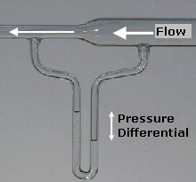
- The flow speed of a fluid can be measured using a device such as a Venturi meter or an orifice plate, which can be placed into a pipeline to reduce the diameter of the flow. For a horizontal device, the continuity equation shows that for an incompressible fluid, the reduction in diameter will cause an increase in the fluid flow speed. Subsequently, Bernoulli's principle then shows that there must be a decrease in the pressure in the reduced diameter region. This phenomenon is known as the Venturi effect.
- The maximum possible drain rate for a tank with a hole or tap at the base can be calculated directly from Bernoulli's equation and is found to be proportional to the square root of the height of the fluid in the tank. This is Torricelli's law, which is compatible with Bernoulli's principle. Increased viscosity lowers this drain rate; this is reflected in the discharge coefficient, which is a function of the Reynolds number and the shape of the orifice.[25]
- The Bernoulli grip relies on this principle to create a non-contact adhesive force between a surface and the gripper.
- During a cricket match, bowlers continually polish one side of the ball. After some time, one side is quite rough and the other is still smooth. Hence, when the ball is bowled and passes through air, the speed on one side of the ball is faster than on the other, and this results in a pressure difference between the sides; this leads to the ball rotating ("swinging") while travelling through the air, giving advantage to the bowlers.
Misconceptions
[edit]Airfoil lift
[edit]One of the most common erroneous explanations of aerodynamic lift asserts that the air must traverse the upper and lower surfaces of a wing in the same amount of time, implying that since the upper surface presents a longer path the air must be moving over the top of the wing faster than over the bottom. Bernoulli's principle is then cited to conclude that the pressure on top of the wing must be lower than on the bottom.[26][27]
Equal transit time applies to the flow around a body generating no lift, but there is no physical principle that requires equal transit time in cases of bodies generating lift. In fact, theory predicts – and experiments confirm – that the air traverses the top surface of a body experiencing lift in a shorter time than it traverses the bottom surface; the explanation based on equal transit time is false.[28][29][30] While the equal-time explanation is false, it is not the Bernoulli principle that is false, because this principle is well established; Bernoulli's equation is used correctly in common mathematical treatments of aerodynamic lift.[31][32]
Common classroom demonstrations
[edit]There are several common classroom demonstrations that are sometimes incorrectly explained using Bernoulli's principle.[33] One involves holding a piece of paper horizontally so that it droops downward and then blowing over the top of it. As the demonstrator blows over the paper, the paper rises. It is then asserted that this is because "faster moving air has lower pressure".[34][35][36]
One problem with this explanation can be seen by blowing along the bottom of the paper: if the deflection was caused by faster moving air, then the paper should deflect downward; but the paper deflects upward regardless of whether the faster moving air is on the top or the bottom.[37] Another problem is that when the air leaves the demonstrator's mouth it has the same pressure as the surrounding air;[38] the air does not have lower pressure just because it is moving; in the demonstration, the static pressure of the air leaving the demonstrator's mouth is equal to the pressure of the surrounding air.[39][40] A third problem is that it is false to make a connection between the flow on the two sides of the paper using Bernoulli's equation since the air above and below are different flow fields and Bernoulli's principle only applies within a flow field.[41][42][43][44]
As the wording of the principle can change its implications, stating the principle correctly is important.[45] What Bernoulli's principle actually says is that within a flow of constant energy, when fluid flows through a region of lower pressure it speeds up and vice versa.[46] Thus, Bernoulli's principle concerns itself with changes in speed and changes in pressure within a flow field. It cannot be used to compare different flow fields.
A correct explanation of why the paper rises would observe that the plume follows the curve of the paper and that a curved streamline will develop a pressure gradient perpendicular to the direction of flow, with the lower pressure on the inside of the curve.[47][48][49][50] Bernoulli's principle predicts that the decrease in pressure is associated with an increase in speed; in other words, as the air passes over the paper, it speeds up and moves faster than it was moving when it left the demonstrator's mouth. But this is not apparent from the demonstration.[51][52][53]
Other common classroom demonstrations, such as blowing between two suspended spheres, inflating a large bag, or suspending a ball in an airstream are sometimes explained in a similarly misleading manner by saying "faster moving air has lower pressure".[54][55][56][57][58][59][60][61]
See also
[edit]- Torricelli's law
- Coandă effect
- Euler equations – for the flow of an inviscid fluid
- Hydraulics – applied fluid mechanics for liquids
- Navier–Stokes equations – for the flow of a viscous fluid
- Teapot effect
- Terminology in fluid dynamics
Notes
[edit]- ^ If the particle is in a region of varying pressure (a non-vanishing pressure gradient in the x-direction) and if the particle has a finite·size l, then the front of the particle will be 'seeing' a different pressure from the rear. More precisely, if the pressure drops in the x-direction (dp/dx < 0) the pressure at the rear is higher than at the front and the particle experiences a (positive) net force. According to Newton's second law, this force causes an acceleration and the particle's velocity increases as it moves along the streamline... Bernoulli's equation describes this mathematically (see the complete derivation in the appendix).[7]
- ^ Acceleration of air is caused by pressure gradients. Air is accelerated in the direction of the velocity if the pressure goes down. Thus the decrease of pressure is the cause of a higher velocity.[8]
- ^ The idea is that as the parcel moves along, following a streamline, as it moves into an area of higher pressure there will be higher pressure ahead (higher than the pressure behind) and this will exert a force on the parcel, slowing it down. Conversely, if the parcel is moving into a region of lower pressure, there will be a higher pressure behind it (higher than the pressure ahead), speeding it up. As always, any unbalanced force will cause a change in momentum (and velocity), as required by Newton's laws of motion.[9]
- ^ "When a stream of air flows past an airfoil, there are local changes in velocity round the airfoil, and consequently changes in static pressure, in accordance with Bernoulli's Theorem. The distribution of pressure determines the lift, pitching moment and form drag of the airfoil, and the position of its centre of pressure."[1]: § 5.5
References
[edit]- ^ a b c d e f g Clancy, L.J. (1975). Aerodynamics. Wiley. ISBN 978-0-470-15837-1.
- ^ a b c d e f g Batchelor, G.K. (2000). An Introduction to Fluid Dynamics. Cambridge: Cambridge University Press. ISBN 978-0-521-66396-0.
- ^ "Hydrodynamica". Britannica Online Encyclopedia. Retrieved 2008-10-30.
- ^ Anderson, J.D. (2016), "Some reflections on the history of fluid dynamics", in Johnson, R.W. (ed.), Handbook of fluid dynamics (2nd ed.), CRC Press, ISBN 9781439849576
- ^ Darrigol, O.; Frisch, U. (2008), "From Newton's mechanics to Euler's equations", Physica D: Nonlinear Phenomena, 237 (14–17): 1855–1869, Bibcode:2008PhyD..237.1855D, doi:10.1016/j.physd.2007.08.003
- ^ a b Streeter, Victor Lyle (1966). Fluid mechanics. New York: McGraw-Hill.
- ^ Babinsky, Holger (November 2003), "How do wings work?", Physics Education, 38 (6): 497–503, Bibcode:2003PhyEd..38..497B, doi:10.1088/0031-9120/38/6/001, S2CID 1657792
- ^ "Weltner, Klaus; Ingelman-Sundberg, Martin, Misinterpretations of Bernoulli's Law, archived from the original on April 29, 2009
- ^ Denker, John S. (2005). "3 Airfoils and Airflow". See How It Flies. Archived from the original on 2007-09-27. Retrieved 2018-07-27.
- ^ Resnick, R.; Halliday, D. (1960). Physics. John Wiley & Sons. section 18–4.
- ^ Mulley, Raymond (2004). Flow of Industrial Fluids: Theory and Equations. CRC Press. pp. 43–44. ISBN 978-0-8493-2767-4.
- ^ Chanson, Hubert (2004). Hydraulics of Open Channel Flow. Elsevier. p. 22. ISBN 978-0-08-047297-3.
- ^ Oertel, Herbert; Prandtl, Ludwig; Böhle, M.; Mayes, Katherine (2004). Prandtl's Essentials of Fluid Mechanics. Springer. pp. 70–71. ISBN 978-0-387-40437-0.
- ^ "Bernoulli's Equation". NASA Glenn Research Center. Archived from the original on 2012-07-31. Retrieved 2009-03-04.
- ^ White, Frank M. Fluid Mechanics (6th ed.). McGraw-Hill International Edition. p. 602.
- ^ Clarke, Cathie; Carswell, Bob (2007). Principles of Astrophysical Fluid Dynamics. Cambridge University Press. p. 161. ISBN 978-1-139-46223-5.
- ^ Landau, L.D.; Lifshitz, E.M. (1987). Fluid Mechanics. Course of Theoretical Physics (2nd ed.). Pergamon Press. ISBN 978-0-7506-2767-2.
- ^ Van Wylen, Gordon J.; Sonntag, Richard E. (1965). Fundamentals of Classical Thermodynamics. New York: John Wiley and Sons.
- ^ a b c Feynman, R.P.; Leighton, R.B.; Sands, M. (1963). The Feynman Lectures on Physics. Vol. 2. Addison-Wesley. ISBN 978-0-201-02116-5.
{{cite book}}: ISBN / Date incompatibility (help): 40–6 to 40–9, §40–3 - ^ Tipler, Paul (1991). Physics for Scientists and Engineers: Mechanics (3rd extended ed.). W. H. Freeman. ISBN 978-0-87901-432-2., p. 138.
- ^ Feynman, R.P.; Leighton, R.B.; Sands, M. (1963). The Feynman Lectures on Physics. Vol. 1. Addison-Wesley. ISBN 978-0-201-02116-5.
{{cite book}}: ISBN / Date incompatibility (help) - ^ Thomas, John E. (May 2010). "The Nearly Perfect Fermi Gas" (PDF). Physics Today. 63 (5): 34–37. Bibcode:2010PhT....63e..34T. doi:10.1063/1.3431329. Archived from the original (PDF) on 2021-03-08. Retrieved 2018-07-27.
- ^ Resnick, R.; Halliday, D. (1960). Physics. New York: John Wiley & Sons. section 18–5.
Streamlines are closer together above the wing than they are below so that Bernoulli's principle predicts the observed upward dynamic lift.
- ^ Eastlake, Charles N. (March 2002). "An Aerodynamicist's View of Lift, Bernoulli, and Newton" (PDF). The Physics Teacher. 40 (3): 166–173. Bibcode:2002PhTea..40..166E. doi:10.1119/1.1466553. "The resultant force is determined by integrating the surface-pressure distribution over the surface area of the airfoil."
- ^ Mechanical Engineering Reference Manual (9th ed.).
- ^ Technical education research center (2006). Physics That Works. Kendall Hunt. ISBN 0787291811. OCLC 61918633.
One of the most widely circulated, but incorrect, explanations can be labeled the "Longer Path" theory, or the "Equal Transit Time" theory.
- ^ Smith, Norman F. (November 1972). "Bernoulli and Newton in Fluid Mechanics". The Physics Teacher. 10 (8): 451. Bibcode:1972PhTea..10..451S. doi:10.1119/1.2352317.
The airfoil of the airplane wing, according to the textbook explanation that is more or less standard in the United States, has a special shape with more curvature on top than on the bottom; consequently, the air must travel over the top surface farther than over the bottom surface. Because the air must make the trip over the top and bottom surfaces in the same elapsed time ..., the velocity over the top surface will be greater than over the bottom. According to Bernoulli's theorem, this velocity difference produces a pressure difference which is lift.
[permanent dead link] - ^ Babinsky, Holger (2003). "How do wings work?" (PDF). Physics Education. 38 (6): 497–503. Bibcode:2003PhyEd..38..497B. doi:10.1088/0031-9120/38/6/001. S2CID 1657792.
...it is often asked why fluid particles should meet up again at the trailing edge. Or, in other words, why should two particles on either side of the wing take the same time to travel from S to T? There is no obvious explanation and real-life observations prove that this is wrong.
- ^ "The actual velocity over the top of an airfoil is much faster than that predicted by the "Longer Path" theory and particles moving over the top arrive at the trailing edge before particles moving under the airfoil."
Glenn Research Center (Aug 16, 2000). "Incorrect Lift Theory #1". NASA. Archived from the original on April 27, 2014. Retrieved June 27, 2021. - ^ Anderson, John (2005). Introduction to Flight. Boston: McGraw-Hill Higher Education. p. 355. ISBN 978-0072825695.
It is then assumed that these two elements must meet up at the trailing edge, and because the running distance over the top surface of the airfoil is longer than that over the bottom surface, the element over the top surface must move faster. This is simply not true. Experimental results and computational fluid dynamic calculations clearly show that a fluid element moving over the top surface of an airfoil leaves the trailing edge long before its companion element moving over the bottom surface arrives at the trailing edge.
- ^ Anderson, David; Eberhardt, Scott. "How Airplanes Fly". How Airplanes Fly: A Physical Description of Lift. Archived from the original on January 26, 2016. Retrieved 26 January 2016.
There is nothing wrong with the Bernoulli principle, or with the statement that the air goes faster over the top of the wing. But, as the above discussion suggests, our understanding is not complete with this explanation. The problem is that we are missing a vital piece when we apply Bernoulli's principle. We can calculate the pressures around the wing if we know the speed of the air over and under the wing, but how do we determine the speed?
- ^ Anderson, John D. (2016). "Chapter 4. Basic Aerodynamics". Introduction to Flight (8th ed.). McGraw-Hill Education.
- ^ "Bernoulli's law and experiments attributed to it are fascinating. Unfortunately some of these experiments are explained erroneously..." Weltner, Klaus; Ingelman-Sundberg, Martin. "Misinterpretations of Bernoulli's Law". Department of Physics, University Frankfurt. Archived from the original on June 21, 2012. Retrieved June 25, 2012.
- ^ Tymony, Cy. "Origami Flying Disk". MAKE Magazine. Archived from the original on 2013-01-03.
This occurs because of Bernoulli's principle — fast-moving air has lower pressure than non-moving air.
- ^ "Bernoulli Effects". School of Physics and Astronomy, University of Minnesota. Archived from the original on 2012-03-10.
Faster-moving fluid, lower pressure. ... When the demonstrator holds the paper in front of his mouth and blows across the top, he is creating an area of faster-moving air.
- ^ "Educational Packet" (PDF). Tall Ships Festival – Channel Islands Harbor. Archived from the original on December 3, 2013. Retrieved June 25, 2012.
Bernoulli's Principle states that faster moving air has lower pressure... You can demonstrate Bernoulli's Principle by blowing over a piece of paper held horizontally across your lips.
- ^ Craig, Gale M. "Physical Principles of Winged Flight". Retrieved March 31, 2016 – via rcgroups.com.
If the lift in figure A were caused by "Bernoulli's principle," then the paper in figure B should droop further when air is blown beneath it. However, as shown, it raises when the upward pressure gradient in downward-curving flow adds to atmospheric pressure at the paper lower surface.
- ^ Babinsky, Holger (2003). "How Do Wings Work" (PDF). Physics Education. 38 (6). IOP Publishing: 497. Bibcode:2003PhyEd..38..497B. doi:10.1088/0031-9120/38/6/001. S2CID 1657792. Retrieved April 7, 2022 – via iopscience.iop.org.
In fact, the pressure in the air blown out of the lungs is equal to that of the surrounding air...
- ^ Eastwell, Peter (2007). "Bernoulli? Perhaps, but What About Viscosity?" (PDF). The Science Education Review. 6 (1). Archived from the original (PDF) on 2018-03-18. Retrieved 2018-03-18.
...air does not have a reduced lateral pressure (or static pressure...) simply because it is caused to move, the static pressure of free air does not decrease as the speed of the air increases, it misunderstanding Bernoulli's principle to suggest that this is what it tells us, and the behavior of the curved paper is explained by other reasoning than Bernoulli's principle.
- ^ Raskin, Jef (February 2003). "Coanda Effect: Understanding Why Wings Work". karmak.org. Archived from the original on 2013-01-13.
Make a strip of writing paper about 5 cm × 25 cm. Hold it in front of your lips so that it hangs out and down making a convex upward surface. When you blow across the top of the paper, it rises. Many books attribute this to the lowering of the air pressure on top solely to the Bernoulli effect. Now use your fingers to form the paper into a curve that it is slightly concave upward along its whole length and again blow along the top of this strip. The paper now bends downward...an often-cited experiment, which is usually taken as demonstrating the common explanation of lift, does not do so...
- ^ Babinsky, Holger (2003). "How Do Wings Work" (PDF). Physics Education. 38 (6). IOP Publishing: 497. Bibcode:2003PhyEd..38..497B. doi:10.1088/0031-9120/38/6/001. S2CID 1657792. Retrieved April 7, 2022 – via iopscience.iop.org.
Blowing over a piece of paper does not demonstrate Bernoulli's equation. While it is true that a curved paper lifts when flow is applied on one side, this is not because air is moving at different speeds on the two sides... It is false to make a connection between the flow on the two sides of the paper using Bernoulli's equation.
- ^ Eastwell, Peter (2007). "Bernoulli? Perhaps, but What About Viscosity?" (PDF). The Science Education Review. 6 (1). Archived from the original (PDF) on 2018-03-18. Retrieved 2018-03-18.
An explanation based on Bernoulli's principle is not applicable to this situation, because this principle has nothing to say about the interaction of air masses having different speeds... Also, while Bernoulli's principle allows us to compare fluid speeds and pressures along a single streamline and... along two different streamlines that originate under identical fluid conditions, using Bernoulli's principle to compare the air above and below the curved paper in Figure 1 is nonsensical; in this case, there aren't any streamlines at all below the paper!
- ^ Auerbach, David. "Why Aircraft Fly" (PDF). European Journal of Physics. 21: 295 – via iopscience.iop.org.
The well-known demonstration of the phenomenon of lift by means of lifting a page cantilevered in one's hand by blowing horizontally along it is probably more a demonstration of the forces inherent in the Coanda effect than a demonstration of Bernoulli's law; for, here, an air jet issues from the mouth and attaches to a curved (and, in this case pliable) surface. The upper edge is a complicated vortex-laden mixing layer and the distant flow is quiescent, so that Bernoulli's law is hardly applicable.
- ^ Smith, Norman F. (November 1972). "Bernoulli and Newton in Fluid Mechanics". The Physics Teacher.
Millions of children in science classes are being asked to blow over curved pieces of paper and observe that the paper 'lifts'... They are then asked to believe that Bernoulli's theorem is responsible... Unfortunately, the 'dynamic lift' involved...is not properly explained by Bernoulli's theorem.
- ^ Denker, John S. "Bernoulli's Principle". See How It Flies. Archived from the original on 2007-09-27 – via av8n.com.
Bernoulli's principle is very easy to understand provided the principle is correctly stated. However, we must be careful, because seemingly-small changes in the wording can lead to completely wrong conclusions.
- ^ Smith, Norman F. (1973). "Bernoulli, Newton and Dynamic Lift Part I". School Science and Mathematics. 73 (3): 181–186. doi:10.1111/j.1949-8594.1973.tb08998.x – via wiley.com.
A complete statement of Bernoulli's Theorem is as follows: 'In a flow where no energy is being added or taken away, the sum of its various energies is a constant: consequently where the velocity increases the pressure decreases and vice versa.'
- ^ Babinsky, Holger (2003). "How Do Wings Work" (PDF). Physics Education. 38 (6). IOP Publishing: 497. Bibcode:2003PhyEd..38..497B. doi:10.1088/0031-9120/38/6/001. S2CID 1657792. Retrieved April 7, 2022 – via iopscience.iop.org.
...if a streamline is curved, there must be a pressure gradient across the streamline, with the pressure increasing in the direction away from the centre of curvature.
- ^ Smith, Norman F. (1973). "Bernoulli, Newton and Dynamic Lift Part II". School Science and Mathematics. 73 (4): 3333. doi:10.1111/j.1949-8594.1973.tb09040.x – via wiley.com.
The curved paper turns the stream of air downward, and this action produces the lift reaction that lifts the paper.
- ^ Aeronautics: An Educator's Guide with Activities in Science, Mathematics, and Technology Education (PDF). NASA. p. 26 – via nasa.gov.
The curved surface of the tongue creates unequal air pressure and a lifting action. ... Lift is caused by air moving over a curved surface.
- ^ Anderson, David F.; Eberhardt, Scott. "The Newtonian Description of Lift of a Wing" (PDF). p. 12. Archived from the original (PDF) on 2016-03-11 – via integener.com.
Viscosity causes the breath to follow the curved surface, Newton's first law says there a force on the air and Newton's third law says there is an equal and opposite force on the paper. Momentum transfer lifts the strip. The reduction in pressure acting on the top surface of the piece of paper causes the paper to rise.
- ^ Anderson, David F.; Eberhardt, Scott. Understanding Flight. p. 229 – via Google Books.
'Demonstrations' of Bernoulli's principle are often given as demonstrations of the physics of lift. They are truly demonstrations of lift, but certainly not of Bernoulli's principle.
- ^ Feil, Max. The Aeronautics File. Archived from the original on May 17, 2015.
As an example, take the misleading experiment most often used to "demonstrate" Bernoulli's principle. Hold a piece of paper so that it curves over your finger, then blow across the top. The paper will rise. However most people do not realize that the paper would not rise if it were flat, even though you are blowing air across the top of it at a furious rate. Bernoulli's principle does not apply directly in this case. This is because the air on the two sides of the paper did not start out from the same source. The air on the bottom is ambient air from the room, but the air on the top came from your mouth where you actually increased its speed without decreasing its pressure by forcing it out of your mouth. As a result the air on both sides of the flat paper actually has the same pressure, even though the air on the top is moving faster. The reason that a curved piece of paper does rise is that the air from your mouth speeds up even more as it follows the curve of the paper, which in turn lowers the pressure according to Bernoulli.
- ^ Geurts, Pim. "Some simple Experiments". sailtheory.com. Archived from the original on 2016-03-03. Retrieved April 7, 2022.
Some people blow over a sheet of paper to demonstrate that the accelerated air over the sheet results in a lower pressure. They are wrong with their explanation. The sheet of paper goes up because it deflects the air, by the Coanda effect, and that deflection is the cause of the force lifting the sheet. To prove they are wrong I use the following experiment: If the sheet of paper is pre bend the other way by first rolling it, and if you blow over it than, it goes down. This is because the air is deflected the other way. Airspeed is still higher above the sheet, so that is not causing the lower pressure.
- ^ Bobrowsky, Matt. "Q: Is It Really Caused by the Bernoulli Effect?". Science 101. National Science Teaching Association.
The Bernoulli effect is commonly—and incorrectly—invoked to explain: :why two suspended balloons or table tennis balls move toward each other when you blow air between them; :why paper rises when you blow air over it; :why a pitched baseball curves; :why a spoon is drawn toward a stream of water; :why a ball remains suspended in an air jet. Here's the news: None of these phenomena is the result of the Bernoulli effect.
- ^ Kamela, Martin (September 2007). "Thinking About Bernoulli". The Physics Teacher. 45 (6). American Association of Physics Teachers: 379–381. Bibcode:2007PhTea..45..379K. doi:10.1119/1.2768700. Archived from the original on February 23, 2013.
Finally, let's go back to the initial example of a ball levitating in a jet of air. The naive explanation for the stability of the ball in the air stream, 'because pressure in the jet is lower than pressure in the surrounding atmosphere,' is clearly incorrect. The static pressure in the free air jet is the same as the pressure in the surrounding atmosphere...
- ^ Smith, Norman F. (November 1972). "Bernoulli and Newton in Fluid Mechanics". The Physics Teacher. 10 (8): 455. Bibcode:1972PhTea..10..451S. doi:10.1119/1.2352317.
Asymmetrical flow (not Bernoulli's theorem) also explains lift on the ping-pong ball or beach ball that floats so mysteriously in the tilted vacuum cleaner exhaust...
- ^ Bauman, Robert P. "The Bernoulli Conundrum" (PDF). introphysics.info. Department of Physics, University of Alabama at Birmingham. Archived from the original (PDF) on February 25, 2012. Retrieved June 25, 2012.
Bernoulli's theorem is often obscured by demonstrations involving non-Bernoulli forces. For example, a ball may be supported on an upward jet of air or water, because any fluid (the air and water) has viscosity, which retards the slippage of one part of the fluid moving past another part of the fluid.
- ^ Craig, Gale M. "Physical Principles of Winged Flight". Retrieved March 31, 2016.
In a demonstration sometimes wrongly described as showing lift due to pressure reduction in moving air or pressure reduction due to flow path restriction, a ball or balloon is suspended by a jet of air.
- ^ Anderson, David F.; Eberhardt, Scott. "The Newtonian Description of Lift of a Wing" (PDF). p. 12. Archived from the original (PDF) on 2016-03-11 – via integener.com.
A second example is the confinement of a ping-pong ball in the vertical exhaust from a hair dryer. We are told that this is a demonstration of Bernoulli's principle. But, we now know that the exhaust does not have a lower value of ps. Again, it is momentum transfer that keeps the ball in the airflow. When the ball gets near the edge of the exhaust there is an asymmetric flow around the ball, which pushes it away from the edge of the flow. The same is true when one blows between two ping-pong balls hanging on strings.
- ^ "Thin Metal Sheets – Coanda Effect". physics.umd.edu. Physics Lecture-Demonstration Facility, University of Maryland. Archived from the original on June 23, 2012. Retrieved October 23, 2012.
This demonstration is often incorrectly explained using the Bernoulli principle. According to the INCORRECT explanation, the air flow is faster in the region between the sheets, thus creating a lower pressure compared with the quiet air on the outside of the sheets.
- ^ "Answer #256". physics.umd.edu. Physics Lecture-Demonstration Facility, University of Maryland. Archived from the original on December 13, 2014. Retrieved December 9, 2014.
Although the Bernoulli effect is often used to explain this demonstration, and one manufacturer sells the material for this demonstration as 'Bernoulli bags,' it cannot be explained by the Bernoulli effect, but rather by the process of entrainment.
External links
[edit]- The Flow of Dry Water - The Feynman Lectures on Physics
- Science 101 Q: Is It Really Caused by the Bernoulli Effect?
- Bernoulli equation calculator
- Millersville University – Applications of Euler's equation
- NASA – Beginner's guide to aerodynamics Archived 2012-07-15 at the Wayback Machine
- Misinterpretations of Bernoulli's equation – Weltner and Ingelman-Sundberg Archived 2012-02-08 at the Wayback Machine