Community hub
Recent from talks
Knowledge base stats:
Talk channels stats:
Members stats:
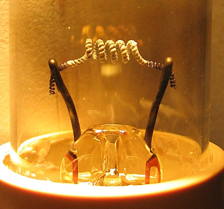
Hot cathode
In vacuum tubes and gas-filled tubes, a hot cathode or thermionic cathode is a cathode electrode which is heated to make it emit electrons due to thermionic emission. This is in contrast to a cold cathode, which does not have a heating element. The heating element is usually an electrical filament heated by a separate electric current passing through it. Hot cathodes typically achieve much higher power density than cold cathodes, emitting significantly more electrons from the same surface area. Cold cathodes rely on field electron emission or secondary electron emission from positive ion bombardment, and do not require heating. There are two types of hot cathode. In a directly heated cathode, the filament is the cathode and emits the electrons. In an indirectly heated cathode, the filament or heater heats a separate metal cathode electrode which emits the electrons.
From the 1920s to the 1960s, a wide variety of electronic devices used hot-cathode vacuum tubes. Today, hot cathodes are used as the source of electrons in fluorescent lamps, vacuum tubes, and the electron guns used in cathode-ray tubes and laboratory equipment such as electron microscopes.
A cathode electrode in a vacuum tube or other vacuum system is a metal surface which emits electrons into the evacuated space of the tube. Since the negatively charged electrons are attracted to the positive nuclei of the metal atoms, they normally stay inside the metal and require energy to leave it. This energy is called the work function of the metal. In a hot cathode, the cathode surface is induced to emit electrons by heating it with a filament, a thin wire of refractory metal like tungsten with current flowing through it. The cathode is heated to a temperature that causes electrons to be 'boiled off' of its surface into the evacuated space in the tube, a process called thermionic emission.
There are two types of hot cathodes:
The main reason for using an indirectly heated cathode is to isolate the rest of the vacuum tube from the electric potential across the filament, allowing vacuum tubes to use alternating current to heat the filament. In a tube in which the filament itself is the cathode, the alternating electric field from the filament surface would affect the movement of the electrons and introduce hum into the tube output. It also allows the filaments in all the tubes in an electronic device to be tied together and supplied from the same current source, even though the cathodes they heat may be at different potentials.
To improve electron emission, cathodes are usually treated with chemicals, compounds of metals with a low work function. These form a metal layer on the surface which emits more electrons. Treated cathodes require less surface area, lower temperatures and less power to supply the same cathode current. The untreated thoriated tungsten filaments used in early vacuum tubes (called "bright emitters") had to be heated to 2,500 °F (1,370 °C), white-hot, to produce sufficient thermionic emission for use, while modern coated cathodes (called "dull emitters") produce far more electrons at a given temperature, so they only have to be heated to 800–1,100 °F (427–593 °C).
The most common type of indirectly heated cathode is the oxide-coated cathode, in which the nickel cathode surface has a coating of alkaline earth metal oxide to increase emission. One of the earliest materials used for this was barium oxide; it forms a monatomic layer of barium with an extremely low work function. More modern formulations utilize a mixture of barium oxide, strontium oxide and calcium oxide. Another standard formulation is barium oxide, calcium oxide, and aluminium oxide in a 5:3:2 ratio. Thorium oxide may be used as well. Oxide-coated cathodes operate at about 800-1000 °C, orange-hot. They are used in most small glass vacuum tubes, but are rarely used in high-power tubes because the coating is degraded by positive ions that bombard the cathode, accelerated by the high voltage on the tube.
For manufacturing convenience, the oxide-coated cathodes are usually coated with carbonates, which are then converted to oxides by heating. The activation may be achieved by microwave heating, direct electric current heating, or electron bombardment while the tube is on the exhausting machine, until the production of gases ceases. The purity of cathode materials is crucial for tube lifetime. The Ba content significantly increases on the surface layers of oxide cathodes down to several tens of nanometers in depth, after the cathode activation process. The lifetime of oxide cathodes can be evaluated with a stretched exponential function. The survivability of electron emission sources is significantly improved by high doping of high‐speed activator.
Hub AI
Hot cathode AI simulator
(@Hot cathode_simulator)
Hot cathode
In vacuum tubes and gas-filled tubes, a hot cathode or thermionic cathode is a cathode electrode which is heated to make it emit electrons due to thermionic emission. This is in contrast to a cold cathode, which does not have a heating element. The heating element is usually an electrical filament heated by a separate electric current passing through it. Hot cathodes typically achieve much higher power density than cold cathodes, emitting significantly more electrons from the same surface area. Cold cathodes rely on field electron emission or secondary electron emission from positive ion bombardment, and do not require heating. There are two types of hot cathode. In a directly heated cathode, the filament is the cathode and emits the electrons. In an indirectly heated cathode, the filament or heater heats a separate metal cathode electrode which emits the electrons.
From the 1920s to the 1960s, a wide variety of electronic devices used hot-cathode vacuum tubes. Today, hot cathodes are used as the source of electrons in fluorescent lamps, vacuum tubes, and the electron guns used in cathode-ray tubes and laboratory equipment such as electron microscopes.
A cathode electrode in a vacuum tube or other vacuum system is a metal surface which emits electrons into the evacuated space of the tube. Since the negatively charged electrons are attracted to the positive nuclei of the metal atoms, they normally stay inside the metal and require energy to leave it. This energy is called the work function of the metal. In a hot cathode, the cathode surface is induced to emit electrons by heating it with a filament, a thin wire of refractory metal like tungsten with current flowing through it. The cathode is heated to a temperature that causes electrons to be 'boiled off' of its surface into the evacuated space in the tube, a process called thermionic emission.
There are two types of hot cathodes:
The main reason for using an indirectly heated cathode is to isolate the rest of the vacuum tube from the electric potential across the filament, allowing vacuum tubes to use alternating current to heat the filament. In a tube in which the filament itself is the cathode, the alternating electric field from the filament surface would affect the movement of the electrons and introduce hum into the tube output. It also allows the filaments in all the tubes in an electronic device to be tied together and supplied from the same current source, even though the cathodes they heat may be at different potentials.
To improve electron emission, cathodes are usually treated with chemicals, compounds of metals with a low work function. These form a metal layer on the surface which emits more electrons. Treated cathodes require less surface area, lower temperatures and less power to supply the same cathode current. The untreated thoriated tungsten filaments used in early vacuum tubes (called "bright emitters") had to be heated to 2,500 °F (1,370 °C), white-hot, to produce sufficient thermionic emission for use, while modern coated cathodes (called "dull emitters") produce far more electrons at a given temperature, so they only have to be heated to 800–1,100 °F (427–593 °C).
The most common type of indirectly heated cathode is the oxide-coated cathode, in which the nickel cathode surface has a coating of alkaline earth metal oxide to increase emission. One of the earliest materials used for this was barium oxide; it forms a monatomic layer of barium with an extremely low work function. More modern formulations utilize a mixture of barium oxide, strontium oxide and calcium oxide. Another standard formulation is barium oxide, calcium oxide, and aluminium oxide in a 5:3:2 ratio. Thorium oxide may be used as well. Oxide-coated cathodes operate at about 800-1000 °C, orange-hot. They are used in most small glass vacuum tubes, but are rarely used in high-power tubes because the coating is degraded by positive ions that bombard the cathode, accelerated by the high voltage on the tube.
For manufacturing convenience, the oxide-coated cathodes are usually coated with carbonates, which are then converted to oxides by heating. The activation may be achieved by microwave heating, direct electric current heating, or electron bombardment while the tube is on the exhausting machine, until the production of gases ceases. The purity of cathode materials is crucial for tube lifetime. The Ba content significantly increases on the surface layers of oxide cathodes down to several tens of nanometers in depth, after the cathode activation process. The lifetime of oxide cathodes can be evaluated with a stretched exponential function. The survivability of electron emission sources is significantly improved by high doping of high‐speed activator.