Hubbry Logo
Ring modulationRing modulationMain
Open search
Ring modulation
Community hub
Ring modulation
logo
8 pages, 0 posts
0 subscribers
Be the first to start a discussion here.
Ring modulation
Ring modulation
from Wikipedia

Schematic diagram of a ring modulator, showing ring of diodes
An example of ring modulation on sine waves of frequency (top) and (middle), producing a variation in amplitude of the sine wave-like frequency on (bottom)[1]

In electronics, ring modulation is a signal processing function, an implementation of frequency mixing, in which two signals are combined to yield an output signal. One signal, called the carrier, is typically a sine wave or another simple waveform; the other signal is typically more complicated and is called the input or the modulator signal.

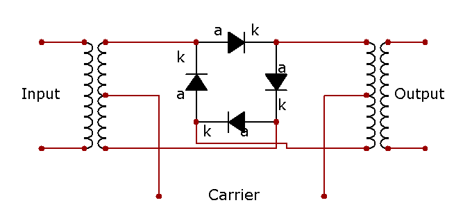
The ring modulator takes its name from the original implementation in which the analog circuit of diodes takes the shape of a ring, a diode ring.[2] The circuit is similar to a bridge rectifier, except that all four diodes are polarized in the same direction.

Ring modulation is similar to amplitude modulation, with the difference that in the latter the modulator is shifted to be positive before being multiplied with the carrier, while in the former the unshifted modulator signal is multiplied with the carrier. This has the effect that ring modulation of two sine waves having frequencies of 1,500 Hz and 400 Hz produce an output signal that is the sum of a sine wave with frequency 1,900 Hz and one with frequency 1,100 Hz. These two output frequencies are known as sidebands. If one of the input signals has significant overtones (which is the case for square waves), the output sounds quite different, since each harmonic generates its own pair of sidebands that is not harmonically-related.[3]

Simplified operation

[edit]

Denoting the carrier signal by , the modulator signal by and the output signal by (where denotes time), ring modulation approximates multiplication:

Double balanced high level frequency mixer Mini-Circuits SBL-1 with four Schottky diodes. LO level +7 dBm (1.41 Vp-p) and RF 1–500 MHz (ADE-1: 0.5–500 MHz)
Macro of the ADE-1
An example of ring modulation on a sine wave of frequency and a square wave of frequency , resulting in a complex sound using analog FM known as diode-clipping or chopper RM, producing a variation in amplitude of the square wave-like frequency on [1]

If and are sine waves with frequencies and , respectively, then is the sum of two (phase-shifted) sine waves, one of frequency and the other of frequency . This is a consequence of the trigonometric identity:

Alternatively, one can use the fact that multiplication in the time domain is the same as convolution in the frequency domain.

Ring modulators thus output the sum and difference of the frequencies present in each waveform. This process of ring modulation produces a signal rich in partials. Neither the carrier nor the incoming signal are prominent in the output, and ideally, not present at all.

Two oscillators, whose frequencies were harmonically related and ring modulated against each other, produce sounds that still adhere to the harmonic partials of the notes but contain a very different spectral makeup. When the oscillators' frequencies are not harmonically related, ring modulation creates inharmonics, often producing bell-like or otherwise metallic sounds.

If the carrier signal is a square wave of frequency , whose Fourier expansion contains the fundamental and a series of reducing-amplitude odd harmonics:

and the carrier frequency is at least twice the maximum frequency of the modulating signal , then the resulting output is a series of duplicates of at increasing regions of the frequency spectrum.[4] For example, let represent a sine wave at 100 Hz, and the carrier be an ideal square wave at 300 Hz. The output then includes sine waves at 100±300 Hz, 100±900 Hz, 100±1500 Hz, 100±2100 Hz, etc., at decreasing amplitudes according to the Fourier expansion of the carrier square wave. If the carrier frequency is less than twice the upper frequency of the signal then the resulting output signal contains spectral components from both the signal and the carrier that combine in the time domain.

Because the output contains neither the individual modulator or carrier components, the ring modulator is said to be a double-balanced mixer,[5] where both input signals are suppressed (not present in the output)—the output is composed entirely of the sum of the products of the frequency components of the two inputs.

History

[edit]

The ring modulator was invented by Frank A. Cowan in 1934 and patented in 1935[6] as an improvement on the invention of Clyde R. Keith at Bell Labs.[7] The original application was in the field of analog telephony for frequency-division multiplexing for carrying multiple voice signals over telephone cables. It has since been applied to a wider range of uses, such as voice inversion, radio transceivers, and electronic music.

While the original Cowan patent describes a circuit with a ring of four diodes, later implementations used FETs as the switching elements.

Circuit description

[edit]

The ring modulator includes an input stage, a ring of four diodes excited by a carrier signal, and an output stage. The input and output stages typically include transformers with center-taps towards the diode ring. While the diode ring has some similarities to a bridge rectifier the diodes in a ring modulator all point in the same clockwise or counterclockwise direction.

The carrier, which alternates between positive and negative current, at any given time makes one pair of diodes conduct, and reverse-biases the other pair. The conducting pair carries the signal from the left transformer secondary to the primary of the transformer at the right. If the left carrier terminal is positive, the top and bottom diodes conduct. If that terminal is negative, then the side diodes conduct, but create a polarity inversion between the transformers. This action is much like that of a DPDT (double pole, double throw) switch wired for reversing connections.

A particular elegance of the ring modulator is that it is bidirectional: the signal flow can be reversed allowing the same circuit with the same carrier to be used either as a modulator or demodulator, for example in low-cost radio transceivers.

Integrated circuit methods of ring modulation

[edit]

Some modern ring modulators are implemented using digital signal processing techniques by simply multiplying the time domain signals, producing a nearly-perfect signal output. Intermodulation products can be generated by carefully selecting and changing the frequency of the two input waveforms. If the signals are processed digitally, the frequency-domain convolution becomes circular convolution. If the signals are wideband, this causes aliasing distortion, so it is common to oversample the operation or low-pass filter the signals prior to ring modulation.

The SID chip found in the Commodore 64 allows for triangle waves to be ring modulated. Oscillator 1 gets modulated by oscillator 3's frequency, oscillator 2 by oscillator 1's frequency, and oscillator 3 by oscillator 2's frequency. Ring modulation is disabled unless the carrier oscillator is set to produce a triangle wave, but the modulating oscillator can be set to generate any of its available waveforms. However, no matter which waveform the modulating oscillator is using, the ring modulation always has the effect of modulating a triangle wave with a square wave.[8][failed verification]

On an ARP Odyssey synthesizer (and a few others from that era as well) the ring modulator is an XOR function (formed from four NAND gates) fed from the square wave outputs of the two oscillators. For the limited case of square or pulse wave signals, this is identical to true ring modulation.

Analog multiplier ICs (such as those made by Analog Devices) would work as ring modulators, of course with regard to such matters as their operating limits and scale factors. Use of multiplier ICs means that the modulation products are largely confined to sum and difference frequency of inputs (unless the circuit is overdriven), rather than the much more complicated products of the rectifier circuit.

Limitations

[edit]

Any DC component of the carrier degrades the suppression of the carrier and thus in radio applications the carrier is typically transformer- or capacitor-coupled; in low frequency (e.g., audio) applications the carrier may or may not be desired in the output.[9]

Imperfections in the diodes and transformers introduce artifacts of the two input signals. In practical ring modulators, this leakage can be reduced by introducing opposing imbalances (e.g., variable resistors or capacitors).

Applications

[edit]

Radio communications

[edit]

Ring modulation has been extensively used in radio receivers, for example, to demodulate an FM stereo signal, and to heterodyne microwave signals in mobile telephone and wireless networking systems. In this case, the circuit is sometimes called a ring demodulator, one of many possible chopper circuits.[10][11] A ring modulator can be used to generate a double-sideband suppressed-carrier (DSB-SC) wave used in radio transmission.[12]

Music and sound effects

[edit]

One of the earliest musical instruments utilizing a ring modulator was the Melochord (1947) built by Harald Bode. It was a two-tone melody keyboard instrument with foot controllers and later added a second keyboard for timbre control, featuring a white-noise generator, envelope controller, formant filters and ring modulators for harmonics.[13] The early Melochord was extensively used by Werner Meyer-Eppler in the early days of the electronic music studio at Bonn University.[14] Meyer-Eppler mentioned the musical application of ring modulator in his book Elektrische Klangerzeugung, published in 1949.[15]

Meyer-Eppler's student Karlheinz Stockhausen used ring modulation in 1956 for some sounds in Gesang der Jünglinge and his realization score for Telemusik (1966[16]) also calls for it. Indeed, several entire compositions by Stockhausen are based around it, such as Mixtur (1964), one of the first compositions for orchestra and live electronics; Mikrophonie II (1965), where the sounds of choral voices are modulated with a Hammond organ; Mantra (1970),[16] where the sounds from two pianos are routed through ring modulators; and Licht-Bilder (2002) from Sonntag aus Licht (2003),[1] which ring-modulates flute and trumpet.[17][18][19] Other Stockhausen pieces employing ring modulation include Kontakte (1960),[1] Mikrophonie I (1964),[1] Hymnen (1969),[1] Prozession (1967),[1] and Kurzwellen (1968).[1]

A ring-modulator was the major component used in Louis and Bebe Barron's music for the film Forbidden Planet (1956). One of the best-known applications of the ring modulator may be its use by Brian Hodgson of the BBC Radiophonic Workshop to produce the distinctive voice of the Daleks in the television series Doctor Who, starting in 1963.[20]

One of the first products dedicated for music was the Bode Ring Modulator developed in 1961 by Harald Bode. Also in 1964 he developed the Bode Frequency Shifter, which produced a clearer sound by eliminating a side band.[21] These devices were designed to be controlled by voltage, compatible with modular synthesizer architecture also advocated by him,[22] and these modules were licensed to R.A. Moog for their Moog modular synthesizers started in 1963–1964.[23] In 1963, Don Buchla included an optional ring modulator in his first modular synthesizer, the Model 100.[24] Also Tom Oberheim built a ring modulator unit for his musician friend in the late 1960s,[25][26] and it became an origin of Oberheim Electronics Music Modulator[27] and Maestro Ring Modulator,[28] one of the earliest ring modulator effect products for guitarists. The EMS VCS3, Synthi A, ARP 2600, Odyssey, Rhodes Chroma and Yamaha CS-80 synthesizers also featured built-in ring modulators.

John McLaughlin employs the ring modulator heavily in the 1974 Mahavishnu Orchestra album Visions of the Emerald Beyond, especially on the track "On the Way Home to Earth". On Miles Davis' 1975 live album Agharta, guitarist Pete Cosey ran the sounds he played through a ring modulator.[29] Deep Purple's Jon Lord fed the signal from his Hammond through a Gibson Ring Modulator unit live on stage, which he described in 1989.[30][31] Founding member of Hawkwind, Dik Mik, a self-confessed non-musician, used a ring modulator as his main instrument during his time with the band (1969-1973).[32]

Vangelis used a ring modulator with his Yamaha CS-80 to improvise his 1978 avant-garde-experimental album Beaubourg. The music on the album is often atonal, with the ring modulator converting the synthesizer's sound into complex metallic timbres.[33] It remains the most experimental released work by the artist, with reviewers calling it "difficult listening at best".[34]

Ring modulation is used in the piece Ofanim (1988/1997) by Luciano Berio, and in the first section is applied to a child's voice and a clarinet: "The transformation of the child voice into a clarinet was desired. For this purpose, a pitch detector computes the instantaneous frequency of the voice. Then the child voice passes through a ring modulator, where the frequency of the carrier is set to . In this case odd harmonics prevail which is similar to the sound of a clarinet in the low register."[35][failed verification]

Analogue telephone systems

[edit]

An early application of the ring modulator was for combining multiple analog telephone voice channels into a single wideband signal to be carried on a single cable using frequency-division multiplexing. A ring modulator in combination with carrier wave and filter was used to assign channels to different frequencies.

Early attempts at securing analog telephone channels used ring modulators to modify the spectrum of the audio speech signals. One application is spectral inversion, typically of speech; a carrier frequency is chosen to be above the highest speech frequencies (which are low-pass filtered at, say, 3 kHz, for a carrier of perhaps 3.3 kHz), and the sum frequencies from the modulator are removed by more low-pass filtering. The remaining difference frequencies have an inverted spectrum: high frequencies become low, and vice versa.

See also

[edit]

References

[edit]
[edit]
Revisions and contributorsEdit on WikipediaRead on Wikipedia
from Grokipedia
Ring modulation is a technique in and audio that multiplies two input signals—a carrier and a modulator—to produce an output containing only the sum and difference of their frequencies, while suppressing the original carrier frequency and eliminating the individual input components. This results in a non-linear frequency-domain transformation that generates new sidebands, often creating metallic, clangorous, or bell-like timbres without the fundamental tones of the inputs. Invented in 1934 by Frank A. Cowan at Bell Laboratories for multiple signals over lines, ring modulation was patented in 1935 and initially served purposes by enabling efficient without carrier transmission. In the , it gained prominence in electronic music through designs by engineer Harald Bode, who adapted it for synthesizers like Robert Moog's early instruments, marking its shift toward creative audio applications. Analog implementations typically employ a ring —four diodes arranged in a ring configuration driven by transformers—to achieve balanced , producing double-sideband suppressed-carrier (DSB-SC) signals that require filtering to isolate desired frequencies. Digital versions, common in modern software and hardware, simulate this process with reduced noise and greater precision, allowing real-time and alteration. Widely used in music synthesis since the mid-20th century, ring modulation produces distinctive effects such as the robotic voices of 's Daleks, eerie soundscapes in films like (1956), and experimental textures by artists like and Kraftwerk. In communications, it facilitates suppressed-carrier AM transmission for bandwidth efficiency, while in sound design, it enables unique harmonic manipulations, from steel drum emulations to spaceship noises, often integrated into synthesizers, effects pedals, and vocal processors.

Fundamentals

Definition and Principles

Ring modulation is a nonlinear technique that multiplies two input signals—a carrier signal and a modulating signal—to produce an output consisting primarily of sum and difference components, while suppressing the original of both inputs. This process, also known as frequency mixing, generates new spectral content through , distinguishing it from linear operations like simple addition or filtering, which preserve the input frequencies without creating harmonics or sidebands. At its core, ring modulation operates as a form of without a residual carrier, where the modulating signal directly scales the amplitude of the carrier instantaneously. In ideal conditions, the output lacks the carrier's , resulting in a double-sideband suppressed-carrier (DSB-SC) signal that emphasizes only the sidebands around the carrier . This suppression occurs because the effectively cancels the DC component of the carrier when the modulator oscillates symmetrically around zero. Mathematically, the time-domain output is expressed as
y(t)=x(t)c(t),y(t) = x(t) \cdot c(t),
where x(t)x(t) represents the modulating signal and c(t)c(t) the carrier signal. In the , this multiplication equates to the of their respective spectra, Y(f)=X(f)C(f)Y(f) = X(f) * C(f), yielding energy at frequencies fc+fmf_c + f_m (sum) and fcfm|f_c - f_m| (difference), where fcf_c and fmf_m are components of the carrier and modulator spectra, respectively. For sinusoidal inputs, this produces discrete sidebands; for complex signals, it generates a dense array of products.
The nonlinear nature of ring modulation—arising from the multiplicative interaction—contrasts with linear modulation schemes, such as , by introducing these new frequency terms that can enrich or distort the signal depending on the input characteristics. This assumes familiarity with basic , including Fourier transforms, where linear systems output sums of input spectra without alteration, whereas nonlinear systems like ring modulation produce convolutions that expand the bandwidth.

Frequency Components

In balanced ring modulation, the output spectrum consists primarily of the upper and lower sidebands generated from the carrier frequency fcf_c and the modulator frequency fmf_m, specifically at fc+fmf_c + f_m and fcfm|f_c - f_m|, while the original carrier and modulator frequencies are suppressed. This spectral transformation arises from the trigonometric product-to-sum identity applied to sinusoidal inputs: sin(2πfct)sin(2πfmt)=12[cos(2π(fc+fm)t)cos(2π(fcfm)t)],\sin(2\pi f_c t) \sin(2\pi f_m t) = \frac{1}{2} \left[ \cos(2\pi (f_c + f_m) t) - \cos(2\pi (f_c - f_m) t) \right], which yields only the sum and difference terms without residual components at fcf_c or fmf_m. The absolute value in the difference frequency accounts for the fact that spectra are conventionally plotted for positive frequencies, mirroring negative components. For a single-tone modulator, such as a pure at fm=100f_m = 100 Hz combined with a carrier at fc=1000f_c = 1000 Hz, the resulting features discrete lines solely at 1100 Hz and 900 Hz, forming symmetric sidebands around the suppressed carrier without any central peak or original tones. In contrast, a multi-tone modulator—such as a complex signal like speech containing multiple harmonics—produces a dense array of sidebands, where each modulator component generates its own pair of sum and difference frequencies relative to fcf_c, often resulting in a broadened, metallic with numerous closely spaced spectral lines. Phase shifts play a key role in the modulator's operation, particularly through the 180-degree inversion of the modulator signal during the negative half-cycle of the carrier, which ensures symmetry in the output and contributes to the effective suppression of DC and original components in the . This inversion affects the phase relationships between sidebands but preserves the locations, though relative phase differences between carrier and modulator can subtly alter the perceived without shifting the spectral peaks. In an ideal ring modulator, perfect balance achieves complete suppression of fcf_c and fmf_m, assuming infinite and precise symmetry, yielding a clean of only the desired sidebands. However, real-world implementations often exhibit imperfect balance due to component mismatches or finite , leading to of residual carrier and modulator tones, as well as from higher-order harmonics (e.g., odd multiples like 3fc±fm3f_c \pm f_m) that require additional filtering to mitigate.

Historical Development

Early Invention

Ring modulation emerged in the early as a technique for balanced modulation to suppress the carrier signal, enabling more efficient in communication s. However, ring modulation developed as a distinct method after to facilitate carrier elimination in amplitude-modulated signals. The key early invention was patented in 1935 by Frank A. Cowan, an engineer at American Telephone and Telegraph, under U.S. Patent No. 2,025,158 (filed June 7, 1934), describing a modulating using a ring of rectifier elements—typically diodes—arranged in a balanced configuration to produce sidebands without the carrier component. This design improved upon prior balanced modulators by enhancing carrier suppression through the symmetric ring arrangement, minimizing leakage and distortion in the output. Cowan's work was primarily motivated by the needs of multi-channel telephony, where efficient multiplexing of signals over limited lines was essential to support expanding long-distance networks without interference. In the context of radio communications, the technique addressed the growing demand for single-sideband suppressed-carrier (SSB) transmission during rise of shortwave broadcasting, allowing transmitters to conserve power by omitting the carrier and one while maintaining over long distances. This efficiency was particularly valuable as expanded, reducing bandwidth usage and power consumption in an era of limited spectrum resources.

Key Milestones

Advancements in diode technology during World War II laid the groundwork for improved modulator performance and reliability in post-war communications systems. In the post-war era, ring modulation saw commercialization in the through its integration into broadcast equipment, particularly for single-sideband suppressed-carrier transmission, which optimized spectrum efficiency in . In the , Harald Bode incorporated ring modulators into electronic musical instruments like the Melochord, marking an early shift toward audio applications. By the early 1970s, the introduction of integrated circuits advanced the technology further, with Motorola's MC1496 balanced modulator IC enabling compact, high-performance implementations in communications devices. The and marked ring modulation's entry into the audio domain, as Bode collaborated with to develop ring modulator modules for modular synthesizers starting in 1963–1964, where it produced distinctive metallic and dissonant sound effects for electronic music composition. Up to 2025, developments have shifted toward hybrid analog-digital configurations in systems, combining analog front-ends for initial mixing with digital processing for flexibility, while pure analog ring modulators persist in niche , valued for their warm, unpredictable timbres in pedals and modules.

Analog Implementation

Circuit Description

Analog ring modulation circuits operate as four-quadrant multipliers, enabling the multiplication of two bipolar input signals to produce an output consisting solely of the sum and difference frequency components, without the original carrier signal. This topology relies on a balanced bridge configuration, where the bridge structure ensures that positive and negative excursions of both signals are handled symmetrically, facilitating complete suppression of the carrier in an ideal setup. The balanced nature of the bridge allows for the processing of signals with both polarities, distinguishing it from simpler modulators that may introduce distortion or carrier remnants. In terms of signal flow, the modulator input—often referred to as the or RF signal—is applied across the bridge, while the carrier signal drives the bridge elements, causing them to switch states in a manner that effectively multiplies the inputs. The output is derived differentially from opposite points of the bridge, which inherently cancels the carrier component through phase opposition, leaving only the modulated sidebands. This differential extraction is crucial for maintaining and achieving the desired frequency mixing without DC offsets or unwanted harmonics propagating to the output. Achieving effective carrier suppression demands precise balance in the circuit components, with mismatches leading to carrier leakage that can degrade performance. Typically, carrier suppression exceeding 40 dB is required for practical applications, necessitating careful matching of bridge elements to within tight tolerances, often through adjustable trims or high-precision . Poor balance can result in output , reducing the modulator's in sensitive systems like communications. Circuit variations include transformer-coupled designs, which use input and output transformers to provide , impedance transformation, and enhanced balance for RF environments, and direct-coupled approaches, which eliminate transformers for wider bandwidth, lower cost, and easier integration into monolithic or hybrid circuits while relying on active elements for balancing. Transformer-coupled versions excel in high-frequency isolation but may introduce bandwidth limitations, whereas direct-coupled designs offer flexibility for to ranges. Early ring modulators employed diodes in the bridge for this switching action, a configuration that laid the foundation for modern implementations.

Diode-Based Modulators

Diode-based ring modulators employ a classic configuration consisting of four arranged in a closed ring, connected between the center taps of two center-tapped . The carrier signal is applied to the primary winding of the first (T1), which drives the ring across opposite diode junctions, while the modulating signal is fed to the primary of the second (T2), with its center taps connected to the diode ring. The output is taken from the secondary winding of T2, often across a load , enabling balanced operation that isolates the signals. In operation, the diodes function as switches controlled by the carrier signal's polarity. When the carrier voltage is positive, one pair of opposite diodes (e.g., D1 and D2) conducts, allowing the modulating signal to pass through unchanged; when negative, the other pair (D3 and D4) conducts, inverting the modulating signal. This alternating conduction effectively multiplies the two input signals, producing sum and difference frequency components at the output while the balanced transformer arrangement cancels the original carrier and modulating signals, yielding suppressed-carrier modulation. The nonlinear voltage-current characteristics of the diodes introduce some , but the minimizes even-order harmonics. Suitable diodes include Schottky types like 1N5711 or SB130 for their low forward (around 0.3 ), which reduces and improves carrier suppression, or germanium diodes such as 1N695 for similar low-threshold performance in audio applications; silicon diodes like 1N4148 can be used but may require biasing for better results. Transformers are typically 1:1 ratio with center taps, rated for 10 kΩ impedance and a from 300 Hz to 100 kHz in audio contexts, though higher-frequency variants support ranges up to 10 MHz in radio applications. Diodes should be matched for consistent forward voltages to ensure balance and minimize unwanted signals. For a hobbyist construction, begin with a featuring oversized holes for leads and DIP-compatible footprints. Solder four matched s in alternating orientations to form the ring between the center taps of two audio s (e.g., Triad SP-66), ensuring the secondary windings face the s for . Attach input jacks for carrier and modulator signals to the primaries, and an output jack across the secondary of the second ; no additional is needed for this passive design. Fine-tuning involves adjusting for balance by swapping s or adding small resistors if carrier breakthrough occurs, allowing operation with line-level audio signals.

Digital Implementation

Algorithms and Methods

In digital signal processing, ring modulation is implemented through direct sample-by-sample multiplication of the input signal xx and the carrier signal cc, yielding the output y=xcy = x \cdot c. This operation produces sum and difference frequencies analogous to analog counterparts, but requires careful management of spectral content to avoid artifacts. To mitigate aliasing from high-frequency components exceeding the Nyquist limit—such as when sum frequencies approach or surpass half the sampling rate—anti-aliasing filters, often low-pass designs, are applied post-multiplication or via techniques like continuous-time convolution approximation. For applications requiring single-sideband (SSB) extraction after ring modulation, quadrature methods employ the to generate an from the modulated output, enabling selective suppression of one . The shifts the phase of negative frequencies by -90 degrees and positive frequencies by +90 degrees, creating a complex representation where multiplication with a complex exponential carrier (e.g., ejωcne^{j\omega_c n}) isolates the upper or lower . In practice, (FIR) or (IIR) filters approximate the ideal Hilbert transformer, with designs like 13th-order elliptic halfband filters achieving low-latency phase shifts for real-time audio processing. This approach extends double-sideband ring modulation to frequency shifting effects while preserving the signal envelope. FPGA and ASIC implementations leverage hardware description languages such as to synthesize dedicated ring modulator cores, utilizing on-chip (DSP) slices for efficient multiplication and accumulation. These cores enable real-time processing at high sampling rates by pipelining the sample-wise operations and integrating carrier oscillators. Precision in digital ring modulation involves trade-offs between floating-point and : 32-bit floating-point formats provide dynamic ranges exceeding 1500 dB with minimal quantization distortion, ideal for high-fidelity audio where carrier amplitudes vary widely. Conversely, fixed-point representations, such as 16- or 32-bit signed integers, offer lower power consumption and faster execution on resource-constrained processors but risk overflow and reduced signal-to-noise ratios (approximately 96 dB for 16-bit or 144 dB for 24-bit fixed-point), necessitating scaling and overflow detection mechanisms.

Software and DSP Applications

In digital audio workstations (DAWs), ring modulation is commonly implemented as an audio effect plugin, enabling musicians and producers to apply the modulation in real-time during mixing and performance. For instance, includes ring modulation functionality within its Frequency Shifter device, which performs balanced modulation to produce sum and difference frequencies without carrier leakage, ideal for creating dissonant or metallic tones in electronic music production. Open-source and visual programming environments further democratize ring modulation implementation. Max/MSP, developed by , allows users to build custom ring modulation patches using the *~ object for signal multiplication, supporting complex routing and integration with hardware controllers for live sound design. Similarly, Pure Data (Pd), an open-source alternative to Max, utilizes the *~ object to achieve ring modulation by multiplying input audio with a carrier signal, facilitating portable, cross-platform applications in installations and education. For embedded systems, ring modulation is realized on specialized digital signal processors (DSPs) to handle real-time audio in resource-constrained environments. Platforms like ' TMS320 family, such as the TMS320C6713, support efficient implementation of modulation algorithms through their multiply-accumulate (MAC) units, commonly used in portable audio devices and gear for low-latency processing. ' SHARC processors, including models like the ADSP-21489, provide high-performance floating-point operations for precise ring modulation in professional audio equipment, leveraging SIMD instructions to minimize computational overhead in effects chains. Modern applications extend ring modulation to consumer platforms. Mobile apps, such as Ringotron for , offer advanced ring modulation with features like phase control and selection, enabling on-device for musicians without requiring a full DAW. In web-based audio, the Web Audio API allows implementations of ring modulation via nodes like GainNode for signal multiplication, supporting real-time browser effects in interactive web apps and online instruments. Digital ring modulation provides key advantages over analog counterparts, including exact carrier suppression to eliminate leakage—achieved through precise digital multiplication without imbalances—and seamless control, such as infinite balance adjustments and frequency tuning via software interfaces. However, in live processing scenarios, digital implementations can suffer from latency due to buffer sizes and algorithmic overhead, typically ranging from 1-10 ms depending on the platform.

Applications

Radio Communications

Ring modulation plays a crucial role in suppressed carrier modulation schemes, particularly in generating double-sideband suppressed carrier (DSB-SC) signals that form the basis for single-sideband suppressed carrier (SSB-SC) transmission in radio communications. By multiplying the modulating audio signal with a carrier using a balanced ring modulator, the carrier is effectively suppressed, eliminating the transmission of unused power while producing symmetric sidebands around the carrier frequency. This DSB-SC output is then filtered to retain only one sideband for SSB-SC, achieving bandwidth savings of approximately 50% compared to conventional double-sideband full carrier (DSB-FC) amplitude modulation (AM), as only the necessary spectral components are transmitted. In terms of power efficiency, SSB-SC allocates all transmitted power to the information-bearing sideband, achieving up to 100% efficiency for the useful signal, in contrast to full AM where the carrier consumes about two-thirds of the total power, limiting efficiency to a maximum of 33% for sinusoidal modulation. On the receiver side, ring modulation is implemented via product detector circuits to demodulate the incoming SSB-SC or DSB-SC signal and recover the original baseband audio. The product detector, often a diode ring configuration, multiplies the received radio frequency (RF) signal with a locally generated carrier from a beat frequency oscillator (BFO), producing sum and difference frequencies that yield the baseband after low-pass filtering. This synchronous demodulation ensures accurate recovery of the modulating signal without distortion from carrier remnants, making it essential for high-fidelity reception in SSB systems. The doubly balanced nature of the ring modulator suppresses both the incoming RF and local oscillator from the output, minimizing interference and improving signal-to-noise ratio in the demodulated audio. International standards from the Radiocommunication Sector () have historically endorsed SSB modulation employing ring-based techniques for shortwave (HF) communications to optimize spectrum use and propagation efficiency. For example, the withdrawn Recommendation ITU-R BS.640-3 (1997, withdrawn 2012) specified parameters such as up to 4.5 kHz audio bandwidth and 5 kHz channel spacing for SSB in HF , with at least 12 dB carrier suppression to reduce interference in crowded bands. In modern (SDR) systems, digital implementations of ring modulation—via numerical in —facilitate efficient up-conversion and down-conversion for flexible frequency translation without analog hardware. These digital mixers enable real-time SSB generation and demodulation in SDR platforms, enhancing adaptability for amateur and professional HF operations. Practical examples in highlight ring modulation's integration, such as in transceiver kits like the uBITX, which uses a diode-based balanced modulator for both SSB transmission and reception across HF bands. This low-cost design achieves carrier suppression and sideband filtering through analog ring modulation principles, supporting efficient QRP (low-power) operations. By the 2020s, hybrid SDR enhancements in similar rigs incorporate digital mixing akin to ring modulation for improved up/down-conversion, allowing seamless band switching and digital mode support while maintaining compatibility with traditional HF protocols.

Audio and Music Synthesis

Ring modulation is widely employed in audio and music synthesis to generate distinctive and inharmonic timbres, often resulting in bell-like or metallic tones that arise from the suppression of original carrier and modulator frequencies, leaving only their sum and difference components. For instance, modulating a carrier signal at 440 Hz with a modulator at 550 Hz produces output frequencies at 990 Hz and 110 Hz, creating an eerie, clangorous suitable for experimental soundscapes. This technique excels at producing non- partials when the modulator frequency is not an multiple of the carrier, enabling composers to craft abstract textures that evoke metallic percussion or otherworldly drones. Historically, ring modulation featured prominently in early analog synthesizers, such as the Moog modular systems introduced in 1965, where it served as a core module for voltage-controlled sound generation in compositions. Similarly, the EMS VCS3 , released in 1969, incorporated a ring modulator renowned for its ability to produce clangorous bell tones, which became a staple in by artists exploring electronic abstraction and noise. In contemporary music production, ring modulation persists through dedicated guitar pedals like the Ring Thing, which offers precise control over carrier tuning and modulation depth to achieve sweeping metallic effects on live instruments. (VST) plugins, such as those integrated into digital audio workstations, extend this capability into software-based synthesis, allowing for real-time parameter automation in track production. Beyond music, ring modulation is a go-to method in film for creating robotic or alien voices, as exemplified by its application to vocal tracks in science fiction productions to impart a synthesized, inhuman quality. Key techniques in musical applications include varying the carrier frequency slowly to simulate vibrato-like pitch undulations on sustained notes, adding subtle movement without altering the core . For enhanced spatial depth, dual ring modulators can be employed in parallel processing, with one handling the left channel and another the right, to create that widens the perceived soundfield and introduces phasing artifacts. These methods highlight ring modulation's versatility in both subtractive synthesis and post-processing effects chains.

Telecommunications

In analog , ring modulation was integral to (FDM) carrier systems, enabling the combination of multiple voice channels over shared transmission media such as coaxial cables and open-wire lines. These systems, exemplified by AT&T's L-carrier introduced in the 1950s, employed ring modulators as balanced modulators to generate double-sideband suppressed-carrier (DSB-SC) signals, which were then filtered to produce single-sideband (SSB) modulation for efficient bandwidth utilization in long-distance networks. Ring modulators facilitated voice frequency shifting in multi-channel links by suppressing the carrier while preserving sidebands, allowing 4 kHz voice bands (typically 300–3400 Hz) to be translated to higher carriers without introducing low-frequency components that could interfere with signals. In standard FDM hierarchies, such as the CCITT basic group, 12 voice channels were modulated onto carriers spaced at 4 kHz intervals within the 60–108 kHz band, with pilot tones inserted at specific frequencies (e.g., 84 kHz for basic groups or 420 kHz for supergroups) for , gain control, and monitoring across the multiplexed assembly. The modulator's carrier suppression minimized spectral inefficiency, though pilot tones themselves were not suppressed but used to maintain system alignment during transmission. By the late , ring modulation in declined sharply as digital (TDM) technologies, such as AT&T's systems based on (PCM), offered superior noise immunity, capacity, and cost efficiency, largely supplanting analog FDM starting in the . However, remnants persist in some rural links, where analog FDM configurations continue to support voice and transmission in areas lacking fiber infrastructure, often as hybrid solutions bridging legacy equipment.

Limitations and Considerations

Inherent Technical Limitations

Ring modulation, as implemented in diode-based circuits, suffers from carrier leakage due to imperfect balance in the modulator components, resulting in a residual carrier signal appearing in the output. This leakage arises primarily from mismatches in the s forming the ring and imbalances in the input and output transformers, which prevent complete cancellation of the carrier. The carrier suppression ratio, a measure of this leakage, is typically in the range of 30 to 60 dB in practical diode ring modulators. Overmodulation distortion occurs in ring modulators when the amplitude of the modulating signal exceeds that of the carrier, leading to incomplete switching of the diodes and the introduction of unwanted harmonics in the output spectrum. In ideal multiplication, ring modulation produces only sum and difference frequencies, but non-ideal diode behavior under these conditions generates intermodulation products, distorting the sidebands and adding extraneous frequency components. This effect is exacerbated in diode ring configurations, where the hard clipping characteristic of the diodes produces bright extra harmonics, reducing the purity of the modulated signal. Dynamic range in ring modulators is inherently limited by the , which restricts the handling of weak modulating signals without degradation, and by quadrature-like imbalances that cause asymmetry between the upper and lower s. The for double-balanced ring mixers is approximately 5.5 dB, setting a fundamental lower bound on detectable signal levels due to and in the s. Imbalances from mismatch or asymmetry introduce even-order products, leading to unequal amplitudes and further compressing the effective , particularly at low signal levels. Bandwidth constraints in ring modulators stem from parasitic capacitances and inductances in the s and s, which limit the operable frequency range for high-frequency carriers. These parasitics introduce phase shifts and at elevated frequencies, degrading the switching of the ring and reducing the modulator's conversion beyond several hundred MHz in typical implementations. bandwidth itself imposes an upper limit, as inter-winding capacitances and leakage inductances cause , confining practical operation to frequencies where component parasitics do not dominate the circuit response.

Practical and Design Challenges

Achieving precise balance in ring modulators is essential to minimize carrier leakage, a persistent issue arising from inherent imbalances in the circuit. In analog -based designs, techniques such as trimming are employed to adjust for variations in forward resistances, enabling carrier suppression levels up to 40-60 dB relative to the sidebands. Auto-nulling circuits, which introduce controlled offsets to the modulating signal port, further enhance rejection by compensating for DC imbalances in the ring. Temperature drift compensation is critical, as thermal variations can alter characteristics and values, leading to gradual degradation in balance; this is often addressed through dedicated compensation networks using matched s to stabilize performance across operating conditions. Component matching plays a pivotal role in maintaining modulator integrity, particularly in analog implementations where mismatches amplify carrier feedthrough and . Diodes and resistors must typically exhibit tight tolerances, such as 1% for resistors and closely matched forward voltages for diodes (e.g., Schottky types), to ensure symmetrical switching and minimize out-of-balance currents at low carrier levels. Aging of components, including degradation over time, exacerbates these issues by shifting matching parameters, potentially reducing suppression ratios by 10-20 dB without recalibration, necessitating periodic maintenance or selection of high-stability parts in long-term deployments. Power efficiency poses distinct challenges in both analog and digital ring modulators. Analog diode-ring configurations demand substantial carrier drive power, often +7 to +17 dBm, to fully switch the diodes and achieve low , resulting in higher overall consumption compared to active alternatives and limiting suitability for battery-powered systems. In digital realizations, low-bit-depth implementations (e.g., 8-12 bits) introduce significant quantization during signal multiplication, elevating the and degrading signal-to-noise ratios by up to 6 dB per bit reduction, particularly in where rounding errors accumulate. This can be mitigated through higher precision or dithering, but at the cost of increased computational overhead. Testing ring modulators focuses on verifying suppression and through established methods, while emerging tools address complexity. Spectrum analyzers are routinely used to measure carrier leakage by injecting a single-tone modulating signal and observing residual carrier amplitude relative to sidebands, targeting suppression better than 40 dB for practical viability. These approaches build on inherent leakage constraints by iteratively optimizing parameters via simulations.

References

Add your contribution
Related Hubs
User Avatar
No comments yet.