Hubbry Logo
search
logo
2135196

Truss bridge

logo
Community Hub0 Subscribers
Read side by side
from Wikipedia
Truss bridge
A truss bridge operated by Southern Pacific Railroad in Contra Costa County, California, converted to pedestrian use and pipeline support
AncestorBeam bridge[citation needed]
RelatedNone
DescendantCantilever bridge, truss arch bridge, transporter bridge, lattice bridge[citation needed]
CarriesPedestrians, pipelines, automobiles, trucks, light rail, heavy rail
Span rangeShort to medium – not very long unless it is continuous
MaterialTimber, iron, steel, reinforced concrete, prestressed concrete
MovableMay be movable – see movable bridge
Design effortMedium
Falsework requiredDepends upon length, materials, and degree of prefabrication

A truss bridge is a bridge whose load-bearing superstructure is composed of a truss, a structure of connected elements, usually forming triangular units. The connected elements, typically straight, may be stressed from tension, compression, or sometimes both in response to dynamic loads. There are several types of truss bridges, including some with simple designs that were among the first bridges designed in the 19th and early 20th centuries. A truss bridge is economical to construct primarily because it uses materials efficiently.

Design

[edit]
The components of a typical truss bridge[1]

The nature of a truss allows the analysis of its structure using a few assumptions and the application of Newton's laws of motion according to the branch of physics known as statics. For purposes of analysis, trusses are assumed to be pin-jointed where the straight components meet, meaning that taken alone, every joint on the structure is functionally considered to be a flexible joint as opposed to a rigid joint with the strength to maintain its shape, and the resulting shape and strength of the structure are only maintained by the interlocking of the components. This assumption means that members of the truss (chords, verticals, and diagonals) will act only in tension or compression. A more complex analysis is required where rigid joints impose significant bending loads upon the elements, as in a Vierendeel truss.

In the bridge illustrated in the infobox at the top, vertical members are in tension, lower horizontal members in tension, shear, and bending, outer diagonal and top members are in compression, while the inner diagonals are in tension. The central vertical member stabilizes the upper compression member, preventing it from buckling. If the top member is sufficiently stiff then this vertical element may be eliminated. If the lower chord (a horizontal member of a truss) is sufficiently resistant to bending and shear, the outer vertical elements may be eliminated, but with additional strength added to other members in compensation. The ability to distribute the forces in various ways has led to a large variety of truss bridge types. Some types may be more advantageous when the wood is employed for compression elements while other types may be easier to erect in particular site conditions, or when the balance between labor, machinery, and material costs has certain favorable proportions.

The inclusion of the elements shown is largely an engineering decision based upon economics, being a balance between the costs of raw materials, off-site fabrication, component transportation, on-site erection, the availability of machinery, and the cost of labor. In other cases, the appearance of the structure may take on greater importance and so influence the design decisions beyond mere matters of economics. Modern materials such as prestressed concrete and fabrication methods, such as automated welding, and the changing price of steel relative to that of labor have significantly influenced the design of modern bridges.

Model bridges

[edit]

A pure truss can be represented as a pin-jointed structure, one where the only forces on the truss members are tension or compression, not bending. This is used in the teaching of statics, by the building of model bridges from spaghetti. Spaghetti is brittle and although it can carry a modest tension force, it breaks easily if bent. A model spaghetti bridge thus demonstrates the use of a truss structure to produce a usefully strong complete structure from individually weak elements.

United States

[edit]

In the United States, because wood was in abundance, early truss bridges would typically use carefully fitted timbers for members taking compression and iron rods for tension members, usually constructed as a covered bridge to protect the structure. In 1820, a simple form of truss, Town's lattice truss, was patented, and had the advantage of requiring neither high labor skills nor much metal. Few iron truss bridges were built in the United States before 1850.

Truss bridges became a common type of bridge built from the 1870s through the 1930s. Examples of these bridges still remain across the US, but their numbers are dropping rapidly as they are demolished and replaced with new structures. As metal slowly started to replace timber, wrought iron bridges in the US started being built on a large scale in the 1870s. Bowstring truss bridges were a common truss design during this time, with their arched top chords. Companies like the Massillon Bridge Company of Massillon, Ohio, and the King Bridge Company of Cleveland, became well-known, as they marketed their designs to cities and townships.

The bowstring truss design fell out of favor due to a lack of durability, and gave way to the Pratt truss design, which was stronger. Again, the bridge companies marketed their designs, with the Wrought Iron Bridge Company in the lead. As the 1880s and 1890s progressed, steel began to replace wrought iron as the preferred material. Other truss designs were used during this time, including the camel-back. By the 1910s, many states developed standard plan truss bridges, including steel Warren pony truss bridges.

In the 1920s and 1930s, Pennsylvania and several states continued to build steel truss bridges, using massive steel through-truss bridges for long spans. Other states, such as Michigan, used standard plan concrete girder and beam bridges, and only a limited number of truss bridges were built.

Roadbed types

[edit]

The truss may carry its roadbed on top, in the middle, or at the bottom of the truss. Bridges with the roadbed at the top or the bottom are the most common as this allows both the top and bottom to be stiffened, forming a box truss. When the roadbed is atop the truss, it is a deck truss; an example of this was the I-35W Mississippi River bridge. When the truss members are both above and below the roadbed it is called a through truss; an example of this is the Pulaski Skyway, and where the sides extend above the roadbed but are not connected, a pony truss or half-through truss.

Sometimes both the upper and lower chords support roadbeds, forming a double-decked truss. This can be used to separate rail from road traffic or to separate the two directions of road traffic.

Since through truss bridges have supports located over the bridge deck, they are susceptible to being hit by overheight loads when used on highways. The I-5 Skagit River bridge collapsed after such a strike; before the collapse, similar incidents had been common and had necessitated frequent repairs.[2]

[edit]
A railway bridge with a rail track in Leflore County, Mississippi

Multiple spans

[edit]

Truss bridges consisting of more than one span may be either a continuous truss or a series of simple trusses. In the simple truss design, each span is supported only at the ends and is fully independent of any adjacent spans. Each span must fully support the weight of any vehicles traveling over it (the live load).

In contrast, a continuous truss functions as a single rigid structure over multiple supports. This means that the live load on one span is partially supported by the other spans, and consequently it is possible to use less material in the truss.[3]: 168  Continuous truss bridges were not very common before the mid-20th century because they are statically indeterminate, which makes them difficult to design without the use of computers.

A multi-span truss bridge may also be constructed using cantilever spans, which are supported at only one end rather than both ends like other types of trusses. Unlike a continuous truss, a cantilever truss does not need to be connected rigidly, or indeed at all, at the center.[3]: 169–170  Many cantilever bridges, like the Quebec Bridge shown below, have two cantilever spans supporting a simple truss in the center. The bridge would remain standing if the simple truss section were removed.

Truss types

[edit]

Bridges are the most widely known examples of truss use. There are many types,[4] some of them dating back hundreds of years. Below are some of the more common designs.

Allan truss

[edit]
An Allan truss

The Allan truss, designed by Percy Allan, is partly based on the Howe truss. The first Allan truss was completed on 13 August 1894 over Glennies Creek at Camberwell, New South Wales and the last Allan truss bridge was built over Mill Creek near Wisemans Ferry in 1929.[5][6] Completed in March 1895, the Tharwa Bridge located at Tharwa, Australian Capital Territory, was the second Allan truss bridge to be built, the oldest surviving bridge in the Australian Capital Territory and the oldest, longest continuously used Allan truss bridge.[7][8][9] Completed in November 1895, the Hampden Bridge in Wagga Wagga, New South Wales, Australia, the first of the Allan truss bridges with overhead bracing, was originally designed as a steel bridge but was constructed with timber to reduce cost.[10] In his design, Allan used Australian ironbark for its strength.[11] A similar bridge also designed by Percy Allen is the Victoria Bridge on Prince Street, Picton, New South Wales. Also constructed of ironbark, the bridge is still in use today for pedestrian and light traffic.[12]

Bailey truss

[edit]

The Bailey truss was designed by the British in 1940–1941 for military uses during World War II. A short selection of prefabricated modular components could be easily and speedily combined on land in various configurations to adapt to the needs at the site and allow rapid deployment of completed trusses. In the image, note the use of pairs of doubled trusses to adapt to the span and load requirements. In other applications the trusses may be stacked vertically, and doubled as necessary.

Bailey truss over the Meurthe River in France

Baltimore truss

[edit]

The Baltimore truss is a subclass of the Pratt truss. A Baltimore truss has additional bracing in the lower section of the truss to prevent buckling in the compression members and to control deflection. It is mainly used for rail bridges, showing off a simple and very strong design. In the Pratt truss the intersection of the verticals and the lower horizontal tension members are used to anchor the supports for the short-span girders under the tracks (among other things). With the Baltimore truss, there are almost twice as many points for this to happen because the short verticals will also be used to anchor the supports. Thus the short-span girders can be made lighter because their span is shorter. A good example of the Baltimore truss is the Amtrak Old Saybrook – Old Lyme Bridge in Connecticut, United States.

Bollman truss

[edit]
A Bollman truss in Savage, Maryland; built in 1869, it was moved to Savage in 1887 and has been in continuous use since as a pedestrian bridge. 39°8′5.42″N 76°49′30.33″W / 39.1348389°N 76.8250917°W / 39.1348389; -76.8250917

The Bollman Truss Railroad Bridge at Savage, Maryland, United States is the only surviving example of a revolutionary design in the history of American bridge engineering. The type was named after its inventor, Wendel Bollman, a self-educated Baltimore engineer. It was the first successful all-metal bridge design (patented in 1852) to be adopted and consistently used on a railroad. The design employs wrought iron tension members and cast iron compression members. The use of multiple independent tension elements reduces the likelihood of catastrophic failure. The structure was also easy to assemble.

Wells Creek Bollman Bridge is the only other bridge designed by Wendel Bollman still in existence, but it is a Warren truss configuration.

Bowstring truss

[edit]
Bowstring truss
A bowstring truss bridge, in London, Ontario, Canada

The bowstring truss bridge was patented in 1841[13] by Squire Whipple.[14] While similar in appearance to a tied-arch bridge, a bowstring truss has diagonal load-bearing members: these diagonals result in a structure that more closely matches a Parker truss or Pratt truss than a true arch.[citation needed]

Brown truss

[edit]
Brown truss

In the Brown truss all vertical elements are under tension, with exception of the end posts. This type of truss is particularly suited for timber structures that use iron rods as tension members.

Brunel truss

[edit]

See Lenticular truss below.

Burr arch truss

[edit]
Baumgardener's Covered Bridge, a Burr Arch Truss in Lancaster County, Pennsylvania

This combines an arch with a truss to form a structure both strong and rigid.

Cantilever truss

[edit]
Forth Bridge, crossing the Firth of Forth in eastern Scotland

Most trusses have the lower chord under tension and the upper chord under compression. In a cantilever truss the situation is reversed, at least over a portion of the span. The typical cantilever truss bridge is a "balanced cantilever", which enables the construction to proceed outward from a central vertical spar in each direction. Usually these are built in pairs until the outer sections may be anchored to footings. A central gap, if present, can then be filled by lifting a conventional truss into place or by building it in place using a "traveling support". In another method of construction, one outboard half of each balanced truss is built upon temporary falsework. When the outboard halves are completed and anchored the inboard halves may then be constructed and the center section completed as described above.

Fink truss

[edit]
A Fink truss (half span and cross section)

The Fink truss was designed by Albert Fink of Germany in 1854. This type of bridge was popular with the Baltimore and Ohio Railroad. The Appomattox High Bridge on the Norfolk and Western Railway included 21 Fink deck truss spans from 1869 until their replacement in 1886.

There are also inverted Fink truss bridges such as the Moody Pedestrian Bridge in Austin, Texas.

Howe truss

[edit]
A Howe truss with diagonals under compression under balanced loading

The Howe truss, patented in 1840 by Massachusetts millwright William Howe, includes vertical members and diagonals that slope up towards the center, the opposite of the Pratt truss.[15] In contrast to the Pratt truss, the diagonal web members are in compression and the vertical web members are in tension. Few of these bridges remain standing. Examples include Jay Bridge in Jay, New York; McConnell's Mill Covered Bridge in Slippery Rock Township, Lawrence County, Pennsylvania; Sandy Creek Covered Bridge in Jefferson County, Missouri; and Westham Island Bridge in Delta, British Columbia, Canada.

K-truss

[edit]
K-truss
The I-895 K-truss in Baltimore

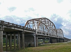
The K-truss is named after the K formed in each panel by the vertical member and two oblique members. Examples include the Südbrücke rail bridge over the River Rhine, Mainz, Germany,[16] the bridge on I-895 (Baltimore Harbor Tunnel Thruway) in Baltimore, Maryland, the Long–Allen Bridge in Morgan City, Louisiana (Morgan City Bridge) with three 600-foot-long spans, and the Wax Lake Outlet bridge in Calumet, Louisiana[17]

Kingpost truss

[edit]
King post truss

One of the simplest truss styles to implement, the king post consists of two angled supports leaning into a common vertical support.

Lattice truss (Town's lattice truss)

[edit]
Lattice, or Warren quadrangular truss illustrated

This type of bridge uses a substantial number of lightweight elements, easing the task of construction. Truss elements are usually of wood, iron, or steel.

Runcorn Railway Bridge, a lattice truss

Lenticular truss

[edit]
Aiken Street Bridge in Lowell, Massachusetts, built in 1883 by Berlin Iron Bridge Co., is the longest lenticular truss bridge in the United States with five spans, and the second-oldest lenticular truss bridge in Massachusetts.[18]

A lenticular truss bridge includes a lens-shape truss, with trusses between an upper chord functioning as an arch that curves up and then down to end points, and a lower chord (functioning as a suspension cable) that curves down and then up to meet at the same end points.[19] Where the arches extend above and below the roadbed, it is called a lenticular pony truss bridge. The Pauli truss bridge is a specific variant of the lenticular truss, but the terms are not interchangeable.[19]

One type of lenticular truss consists of arcuate upper compression chords and lower eyebar chain tension links. Brunel's Royal Albert Bridge over the River Tamar between Devon and Cornwall uses a single tubular upper chord. As the horizontal tension and compression forces are balanced these horizontal forces are not transferred to the supporting pylons (as is the case with most arch types). This in turn enables the truss to be fabricated on the ground and then to be raised by jacking as supporting masonry pylons are constructed. This truss has been used in the construction of a stadium,[20] with the upper chords of parallel trusses supporting a roof that may be rolled back. The Smithfield Street Bridge in Pittsburgh, Pennsylvania, is another example of this type.

An example of a lenticular pony truss bridge that uses regular spans of iron is the Turn-of-River Bridge designed and manufactured by the Berlin Iron Bridge Co.

The Pauli truss is a variant of the lenticular truss, "with the top chord carefully shaped so that it has a constant force along the entire length of the truss."[19] It is named after Friedrich Augustus von Pauli [de], whose 1857 railway bridge (the Großhesseloher Brücke [de]) spanned the Isar near Munich. (See also Grosshesselohe Isartal station.) The term Pauli truss is not interchangeable with the term lenticular truss and, according to Thomas Boothby, the casual use of the term has clouded the literature.[19]

Long truss

[edit]
HAER diagram of a Long truss

The Long truss was designed by Stephen H. Long in 1830. The design resembles a Howe truss, but is entirely made of wood instead of a combination of wood and metal.[21] The longest surviving example is the Eldean Covered Bridge north of Troy, Ohio, spanning 224 feet (68 m).[22] One of the earliest examples is the Old Blenheim Bridge, which with a span of 210 feet (64 m) and a total length of 232 feet (71 m) long was the second-longest covered bridge in the United States, until its destruction from flooding in 2011.

The Busching bridge, often erroneously used as an example of a Long truss, is an example of a Howe truss, as the verticals are metal rods.[23]

Parker (camelback) truss

[edit]
Woolsey Bridge, a Parker camelback truss

A Parker truss bridge is a Pratt truss design with a polygonal upper chord. A "camelback" is a subset of the Parker type, where the upper chord consists of exactly five segments. An example of a Parker truss is the Traffic Bridge in Saskatoon, Canada. An example of a camelback truss is the Woolsey Bridge near Woolsey, Arkansas.

Partridge truss

[edit]
Partridge truss design

Designed and patented in 1872 by Reuben Partridge, after local bridge designs proved ineffective against road traffic and heavy rains.[24] It became the standard for covered bridges built in central Ohio in the late 1800s and early 1900s.

Pegram truss

[edit]
Pegram truss

The Pegram truss is a hybrid between the Warren and Parker trusses where the upper chords are all of equal length and the lower chords are longer than the corresponding upper chord. Because of the difference in upper and lower chord length, each panel is not square. The members which would be vertical in a Parker truss vary from near vertical in the center of the span to diagonal near each end, similar to a Warren truss. George H. Pegram, while the chief engineer of Edge Moor Iron Company in Wilmington, Delaware, patented this truss design in 1885.[25]

The Pegram truss consists of a Parker type design with the vertical posts leaning towards the center at an angle between 60 and 75°. The variable post angle and constant chord length allowed steel in existing bridges to be recycled into a new span using the Pegram truss design. This design also facilitated reassembly and permitted a bridge to be adjusted to fit different span lengths. There are twelve known remaining Pegram span bridges in the United States with seven in Idaho, two in Kansas, and one each in California, Washington, and Utah.[citation needed]

Pennsylvania (Petit) truss

[edit]
The Fair Oaks Bridge is an example of Pennsylvania Petit truss bridge.

The Pennsylvania (Petit) truss is a variation on the Pratt truss.[26] The Pratt truss includes braced diagonal members in all panels; the Pennsylvania truss adds to this design half-length struts or ties in the top, bottom, or both parts of the panels. It is named after the Pennsylvania Railroad, which pioneered this design. It was once used for hundreds of bridges in the United States, but fell out of favor in the 1930s and very few examples of this design remain.[27] Examples of this truss type include the Lower Trenton Bridge in Trenton, New Jersey, the Fort Wayne Street Bridge in Goshen, Indiana, the Schell Bridge in Northfield, Massachusetts, the Inclined Plane Bridge in Johnstown, Pennsylvania, the Easton–Phillipsburg Toll Bridge in Easton, Pennsylvania, the Boston and Maine Connecticut River Rail Bridge in Brattleboro, Vermont, the Metropolis Bridge in Metropolis, Illinois, and the Healdsburg Memorial Bridge in Healdsburg, California.


Post truss

[edit]
A Post truss

A Post truss is a hybrid between a Warren truss and a double-intersection Pratt truss. Invented in 1863 by Simeon S. Post, it is occasionally referred to as a Post patent truss although he never received a patent for it.[28] The Ponakin Bridge and the Bell Ford Bridge are two examples of this truss.


Pratt truss

[edit]
A Pratt truss
Gatton Railway Bridge showing the Pratt truss design

A Pratt truss includes vertical members and diagonals that slope down towards the center, the opposite of the Howe truss.[15] The interior diagonals are under tension under balanced loading and vertical elements under compression. If pure tension elements (such as eyebars) are used in the diagonals, then crossing elements may be needed near the center to accept concentrated live loads as they traverse the span. It can be subdivided, creating Y- and K-shaped patterns. The Pratt truss was invented in 1844 by Thomas and Caleb Pratt.[29][30] This truss is practical for use with spans up to 250 feet (76 m) and was a common configuration for railroad bridges as truss bridges moved from wood to metal. They are statically determinate bridges, which lend themselves well to long spans. They were common in the United States between 1844 and the early 20th century.[30]

Examples of Pratt truss bridges are the Governor's Bridge in Maryland;[30] the Hayden RR Bridge in Springfield, Oregon, built in 1882; the Dearborn River High Bridge near Augusta, Montana, built in 1897; and the Fair Oaks Bridge in Fair Oaks, California, built 1907–09.

The Scenic Bridge near Tarkio, Montana, is an example of a Pratt deck truss bridge, where the roadway is on top of the truss.

Queenpost truss

[edit]
A Queen post truss

The queenpost truss, sometimes called "queen post" or queenspost, is similar to a king post truss in that the outer supports are angled towards the center of the structure. The primary difference is the horizontal extension at the center which relies on beam action to provide mechanical stability. This truss style is only suitable for relatively short spans.[31]


Smith truss

[edit]
Smith truss

The Smith truss, patented by Robert W Smith on July 16, 1867,[32] has mostly diagonal criss-crossed supports. Smith's company used many variations of this pattern in the wooden covered bridges it built.

While most all of the bridges built in the 19th century in the Jackson County, Ohio, area used the Smith truss design, the Johnson Road Covered Bridge is the last known surviving example in the state.[33]


Thacher truss

[edit]
A Thacher truss bridge

The Thacher truss [34] combines some of the characteristics of a Pratt truss with diagonals under tension and of a Howe truss with diagonals under compression, which is rare.


Truss arch

[edit]
Truss arch bridge

A truss arch may contain all horizontal forces within the arch itself, or alternatively may be either a thrust arch consisting of a truss, or of two arcuate sections pinned at the apex. The latter form is common when the bridge is constructed as cantilever segments from each side as in the Navajo Bridge.


Vierendeel truss

[edit]
A Vierendeel bridge

The Vierendeel truss, unlike common pin-jointed trusses, imposes significant bending forces upon its members—but this in turn allows the elimination of many diagonal elements. It is a structure where the members are not triangulated but form rectangular openings, and is a frame with fixed joints that are capable of transferring and resisting bending moments. While rare as a bridge type due to higher costs compared to a triangulated truss, it is commonly employed in modern building construction as it allows the resolution of gross shear forces against the frame elements while retaining rectangular openings between columns. This is advantageous both in allowing flexibility in the use of the building space and freedom in selection of the building's outer curtain wall, which affects both interior and exterior styling aspects.


Waddell truss

[edit]
Waddell "A" truss bridge, assembled in 1898

Patented 1894 (U.S. patent 529,220); its simplicity eases erection at the site. It was intended to be used as a railroad bridge.

One example was the Waddell "A" Truss Bridge in Parkville, Missouri.

Warren truss

[edit]
A Warren truss

The Warren truss was patented in 1848 by James Warren and Willoughby Theobald Monzani, and consists of longitudinal members joined only by angled cross-members, forming alternately inverted equilateral triangle-shaped spaces along its length, ensuring that no individual strut, beam, or tie is subject to bending or torsional straining forces, but only to tension or compression. Loads on the diagonals alternate between compression and tension approaching the center, with no vertical elements, while elements near the center must support both tension and compression in response to live loads. This configuration combines strength with economy of materials and can therefore be relatively light. The girders being of equal length, it is ideal for use in prefabricated modular bridges. It is an improvement over the Neville truss which uses a spacing configuration of isosceles triangles.

Whipple truss

[edit]

A Whipple truss, named after its inventor Squire Whipple, is usually considered a subclass of the Pratt truss because the diagonal members are designed to work in tension. The main characteristic of a Whipple truss is that the tension members are elongated, usually thin, and at a shallow angle, and cross two or more bays (rectangular sections defined by the vertical members). An example of the double-intersection Whipple truss is Bridge L-158 in Golden's Bridge, New York.

Bridge L-158, a double-intersection Whipple rail truss over the Muscoot Reservoir in Golden's Bridge, New York

Wichert truss

[edit]
Homestead Grays Bridge over the Monongahela River in Pittsburgh

The Wichert truss is a modified type of continuous truss which is statically determinate and helps avoid some of the other shortcomings of continuous trusses.[35] It was patented in 1930 by Pittsburgh-based civil engineer Edward Martin Wichert (1883–1955).[36][37]

The defining feature of this truss type is a hinged kite-shaped section above each intermediate support.[citation needed] Only about ten Wichert truss bridges were ever built, mostly in Pennsylvania and Maryland. Of these, one of the best known is the Homestead Grays Bridge in Pittsburgh.[38]

Video

[edit]
Driving across a truss bridge in Lane County, Oregon

Driving across a truss bridge: The video shows the roadway perspective of a through truss bridge over the Willamette River in Harrisburg, Oregon. The bridge features three simply supported Parker Truss spans.

References

[edit]

Footnotes

[edit]
[edit]
Revisions and contributorsEdit on WikipediaRead on Wikipedia
from Grokipedia
A truss bridge is a type of bridge whose load-bearing superstructure consists of a truss, a framework of interconnected structural elements—typically straight members—forming a series of triangular units that primarily experience axial forces of tension or compression to support loads efficiently.[1] These elements are joined at joints using pinned, riveted, or bolted connections, allowing the structure to distribute stresses evenly across the framework without significant bending moments in the members.[2] Truss bridges are categorized by their configuration relative to the deck, including through trusses (where the roadway passes through the structure), pony trusses (a lighter through type with the deck at the bottom chords), and deck trusses (where the roadway is above the truss). The origins of truss bridges trace back to ancient wooden constructions using basic triangular forms like kingpost and queenpost trusses for short spans, but the modern form emerged in the early 19th century in the United States with designs such as Theodore Burr's arch-supplemented truss, introduced in 1806, which enabled longer crossings over rivers and valleys.[3] The advent of iron and steel in the mid-1800s revolutionized truss bridges, particularly for railroads, with key innovations including the Pratt truss (patented 1844 by Thomas and Caleb Pratt, featuring vertical members in compression and diagonals in tension) and the Howe truss (1840 by William Howe, reversing those force directions).[4] By the late 19th century, metal truss bridges became the dominant type for highway and rail infrastructure in North America due to their scalability and the growing demand for efficient transportation networks.[5] Common truss designs also encompass the Warren truss (1848, with equilateral triangles and no verticals for simplicity) and variants like the Parker (curved top chord for longer spans) and Baltimore (a Pratt derivative for heavy loads), each optimized for specific span lengths and load requirements in civil engineering applications.[6] These bridges offer structural advantages, including the use of relatively small members to achieve greater depths and spans—up to several hundred feet—while minimizing material compared to solid beam designs, as the triangular geometry provides inherent rigidity against deformation.[7] In contemporary engineering, truss bridges remain relevant for medium-span crossings where prefabrication and axial load efficiency reduce construction costs, though they are often supplemented with modern materials like high-strength steel for enhanced durability.[1]

Fundamentals

Definition and principles

A truss bridge is a bridge whose load-bearing superstructure consists of a truss, a framework of interconnected elements—typically straight bars or tubes—forming triangular units that efficiently distribute applied loads across the structure. These triangular configurations ensure that forces from the deck, traffic, and environmental loads are transferred through the members to the supports, providing overall stability without relying on continuous solid sections.[8][9] The core engineering principle of a truss bridge lies in its rigidity, achieved through triangulation, where interconnected triangles resist deformation under load by maintaining geometric stability. In an ideal truss, members are connected at joints via pins or hinges, allowing forces to act primarily as axial loads—tension, which elongates the member, or compression, which shortens it—aligned along the member's length. This setup minimizes shear and bending moments, as joints transmit only forces parallel to the connected members; for instance, a compressive force in one member pushes against the joint, balanced by tensile forces in adjacent members, forming a closed vector diagram of equilibrium at each node. Various configurations like Warren or Pratt trusses build on these principles.[9][10][7] Truss bridges provide a high strength-to-weight ratio and material efficiency, as the triangulated framework distributes stresses evenly, enabling slender members to handle substantial loads with less material than solid beams of equivalent capacity. The open web design further enhances this by permitting greater structural depth for the same material volume, optimizing resistance to axial forces. They are well-suited for medium to long spans, typically 50-300 meters, with exceptional designs achieving over 400 meters, where longer distances become feasible without excessive material use.[7][8] Unlike beam bridges, which endure significant bending moments and shear across their depth, truss bridges avoid these in their members by converting loads into pure axial forces through the rigid triangular lattice. Arch bridges manage loads mainly via compression along curved ribs, directing forces outward to abutments, while suspension bridges rely on tensile cables to suspend the deck from towers; truss bridges, by contrast, integrate both tension and compression elements for a balanced, efficient force-handling system.[11][9]

Historical development

The concept of truss bridges evolved from ancient wooden frameworks that provided structural stability through triangulation. In ancient Rome, timber was employed in simple beam and cantilever designs, serving as precursors to more rigid truss systems. Similarly, Chinese engineers developed timber arch bridges from the Song dynasty (11th century) onward, incorporating woven rib and lattice elements to distribute loads effectively. These early adaptations laid foundational principles for load-bearing frameworks using readily available wood.[12] By the 18th century, European innovations advanced truss designs toward greater spans and durability. Swiss builders Hans and Johannes Grubenmann pioneered combinations of wooden trusses and arches in the 1760s, enabling bridges up to 60 meters long, such as the 1766 Wettingen Bridge over the Limmat River. The introduction of iron in late 18th-century Europe marked a shift, with cast iron used for compression members and wrought iron for tension, though full iron trusses emerged in the 19th century. In the United States, Ithiel Town patented the lattice truss in 1820, a lightweight wooden design using crisscrossed diagonal planks pinned together, which allowed rapid construction by unskilled labor and became widely licensed for spans up to 30 meters, influencing early American and European covered bridges.[13][14][15] The 19th century brought transformative advancements through wrought iron and steel, driven by railroad expansion. Squire Whipple, an American engineer, constructed the first iron bowstring truss in 1841 and patented an improved double-intersection version in 1847, along with the first theoretical stress calculation methods in his treatise A Work on Bridge Building, standardizing iron applications for canals and early rail crossings. Thomas and Caleb Pratt patented their truss design in 1844, featuring vertical compression posts and diagonal tension rods, which proved efficient for heavy railroad loads and was adopted extensively in the U.S. for spans of 20 to 50 meters. These innovations facilitated the rapid growth of rail networks, with metal trusses enabling reliable, prefabricated structures over challenging terrains in North America and Europe. In Asia, adaptations of truss principles appeared in Japanese and Chinese timber designs, blending local joinery with imported Western iron techniques for regional infrastructure.[16][17][18][19][20] The 20th century standardized steel in truss construction, peaking during World War II with the portable Bailey truss, developed by British engineer Donald Bailey in 1940–1941 as a prefabricated, modular design assemblable by small crews without heavy equipment; over 4,500 units supported Allied advances in Europe and North Africa by enabling quick river crossings. Post-1950s, new truss highway bridges declined sharply due to advancements in prestressed concrete and cable-stayed designs, which accommodated longer spans (over 100 meters) and multi-lane traffic more economically. Nonetheless, trusses resurged in the late 20th and 21st centuries for pedestrian and rail uses, valued for medium-span efficiency and heritage preservation, with many historic steel examples rehabilitated for non-motorized paths. In the 2020s, sustainability drives hybrid innovations, such as steel-concrete composites and fiber-reinforced polymers (FRP), reducing weight by up to 25% and carbon emissions; the 2024 Paradis Hybrid Truss in Europe exemplifies this, combining carbon fiber chords with steel for durable, low-maintenance rail-pedestrian spans.[21][22][23][24][25][26][27]

Design and engineering

Structural components

A truss bridge's primary structural components include the top chord, bottom chord, web members, and end posts or portals, which collectively form a network of interconnected elements designed for efficient load transfer. The top and bottom chords serve as the principal horizontal members, spanning the length of the bridge and forming the upper and lower edges of the truss framework; they primarily resist bending moments through axial forces, with the top chord under compression and the bottom chord under tension in typical load scenarios.[8][28] Web members, consisting of vertical and diagonal elements, interconnect the chords to create rigid triangular units that distribute shear forces and maintain structural integrity.[1][29] End posts, positioned at the truss extremities, act as vertical or inclined supports that channel loads directly to the bridge's abutments or piers, while portals—often comprising bracing frames at the ends—enhance lateral stability against transverse movements.[30][31] Joints and connections are critical for assembling these components, enabling force transfer without excessive deformation. Traditional truss designs employ pinned joints, which permit rotation at connection points to ensure members experience primarily axial loading rather than bending; in contrast, rigid joints provide moment resistance but are less common in basic truss configurations due to increased complexity.[32][33] For steel trusses, gusset plates—flat, perforated steel sheets—are bolted or riveted to overlap multiple members at nodes, facilitating secure and prefabricated assembly.[34][35] Counterbraces, supplementary diagonal members often installed in the lateral or sway planes, provide additional resistance to wind and seismic forces, preventing buckling or distortion.[36] The evolution of materials has significantly influenced truss bridge durability and span capabilities. Early constructions relied on wood for its availability and ease of shaping into triangular frameworks, but limitations in strength led to the adoption of wrought iron during the mid-19th century for better tensile properties in tension members.[1][3] By the late 19th century, steel supplanted iron due to its superior strength-to-weight ratio and weldability, enabling longer spans and more standardized production.[1][5] In modern applications, high-strength steel alloys, such as weathering steels with enhanced corrosion resistance, are prevalent, often combined with prestressed elements to pre-compress members and counteract tensile stresses for optimized performance.[37] Standard diagrams of a generic truss illustrate these components through labeled conventions: nodes (or joints) mark intersection points where forces concentrate, while members are denoted as line segments—horizontal for chords, vertical for posts, and sloped for diagonals—highlighting the triangular geometry that ensures the structure's stability and load path efficiency.[28][36]

Force analysis and load distribution

Truss bridges experience a variety of loads that must be carefully analyzed for safe design. Dead loads consist of the permanent weight of the structure itself, including the truss members, deck, and railings, while live loads arise from transient traffic such as vehicles and pedestrians. Environmental loads, including wind forces acting transversely and seismic accelerations inducing dynamic responses, also contribute to the overall loading. These loads are applied to the roadbed—whether at the top, bottom, or mid-height of the truss—and transferred to the joints as concentrated forces, with dead and live loads from the deck often modeled as point loads on floor beams framing into the truss.[38][39][40] Engineers analyze force distribution in truss bridges using established statics methods, assuming members carry only axial loads and joints behave as pins. The method of joints examines equilibrium at each connection point, solving for unknown member forces by applying the conditions Fx=0\sum F_x = 0 and Fy=0\sum F_y = 0 (with Fz=0\sum F_z = 0 for three-dimensional trusses), starting from joints with at most two unknowns. This approach is systematic for determining all internal forces but becomes computationally intensive for large trusses. Forces act along the chords, which primarily resist bending through axial tension and compression, and the web members, which handle shear.[41][42] For efficiency in finding forces in select members, the method of sections involves cutting the truss through a plane that intersects the desired members, creating a free-body diagram of the isolated segment, and applying the three equilibrium equations (Fx=0\sum F_x = 0, Fy=0\sum F_y = 0, M=0\sum M = 0) to solve for the axial forces exposed by the cut. This technique isolates segments without needing to analyze every joint, making it suitable for verifying critical member stresses.[43][44] To address moving live loads like vehicular traffic, influence lines are used to identify load positions that maximize forces or moments in specific members. These lines represent the variation in a response quantity (e.g., member force) as a unit load traverses the span, allowing engineers to position multiple loads for the worst-case scenario by scaling and superposing the ordinates under the load configuration.[45][46] Stress analysis in truss members focuses on axial tension, compression, and stability, with compression chords and webs particularly susceptible to buckling under load. The critical buckling load for slender compression members is given by Euler's formula:
Pcr=π2EI(KL)2 P_{cr} = \frac{\pi^2 E I}{(K L)^2}
where EE is the modulus of elasticity, II is the cross-sectional moment of inertia, LL is the unbraced length, and KK is the effective length factor accounting for end conditions. Designs incorporate a factor of safety to prevent failure, traditionally applied as a multiplier (e.g., 1.48 for truss compression members under service loads) or, in modern practice, through load factors and resistance factors in AASHTO LRFD specifications to achieve equivalent reliability.[47][48][49]

Modeling and construction techniques

Truss bridges have historically relied on scale modeling to validate designs and test load-bearing capacities before full-scale construction. In the early 19th century, engineers constructed physical wood models to simulate structural behavior under applied loads, allowing for empirical assessment of stability and failure points in truss configurations.[50] These models, often built at reduced scales such as 1:10 or 1:20, were subjected to incremental loading to observe deflections and identify weak joints, a practice that informed the design of early iron and steel trusses.[51] Modern modeling has shifted toward virtual simulations using finite element analysis (FEA) software, which enables precise prediction of stress distributions and deformations in truss members without physical prototypes. Tools like ANSYS or SAP2000 discretize the truss into finite elements—typically beam or truss elements—to solve equilibrium equations under various load cases, including dead, live, and environmental loads.[52] FEA models verify load distributions from theoretical force analyses, ensuring compliance with standards such as those from the American Association of State Highway and Transportation Officials (AASHTO).[53] This approach reduces costs and time compared to physical testing while accommodating complex geometries in multi-span trusses. Construction techniques for truss bridges emphasize prefabrication to enhance efficiency and precision. Truss panels and members are typically fabricated off-site in controlled environments, where steel components are cut, shaped, and assembled into modular sections before transportation to the site.[54] Erection methods include cantilever launching, where successive truss segments are progressively extended from support piers using temporary stays and counterweights, minimizing the need for extensive scaffolding over waterways or challenging terrains.[55] Derrick systems or cranes hoist prefabricated panels into position, with alignment ensured through temporary bracing. The evolution of joint connections has paralleled advancements in fabrication technology, transitioning from riveting in the late 19th century to bolting and welding in contemporary practice. Riveting, dominant from the 1860s to the mid-20th century, involved heating and hammering iron or steel pins through overlapping plates for a tight fit, providing reliable shear resistance in historic trusses.[56] Bolted connections, introduced widely post-World War II, use high-strength bolts for easier on-site assembly and disassembly, offering flexibility for maintenance.[37] Welding, now preferred for permanent shop-fabricated joints, fuses members directly via electric arcs, reducing weight and labor while achieving higher strength-to-weight ratios, though it requires non-destructive testing to detect flaws.[57] Quality control during construction and maintenance focuses on ensuring member alignment, joint integrity, and overall structural resilience. Inspections involve visual checks, ultrasonic testing for welds, and torque verification for bolts to confirm compliance with tolerances specified in AASHTO guidelines, preventing premature failures from misalignment or corrosion.[58] For existing truss bridges, seismic retrofitting techniques include adding dampers, base isolators, or supplemental bracing to enhance ductility and energy dissipation, particularly at connections vulnerable to earthquake-induced shear.[59] These measures, often informed by FEA simulations of seismic events, extend service life while maintaining load-carrying capacity. Physical and digital models continue to play a key role in design validation, with historical examples from military engineering programs demonstrating their utility in rapid prototyping. For instance, scale models tested by engineering corps validated truss designs under simulated battlefield loads, influencing standardized constructions.[51] In current practice, 3D printing facilitates the creation of detailed prototypes for truss components, allowing engineers to assess fit, strength, and manufacturability at low cost before committing to metal fabrication.[60] These prototypes, often scaled at 1:50 or smaller, undergo load testing to refine joint designs and predict real-world performance.

Configurations

Roadbed positions

Truss bridges are classified by the position of the roadbed relative to the truss framework, which influences structural stability, clearance requirements, and load distribution. The primary configurations include deck, through, pony, and half-through trusses, each suited to specific span lengths, load types, and site constraints. These positions determine how vertical and lateral forces interact with the top and bottom chords, as well as the need for additional bracing.[61] In a deck truss, the roadbed is positioned on top of the truss structure, with the traffic load applied directly to the upper chord. This configuration results in a shallow overall profile for the bridge, maximizing vertical clearance beneath for navigation or other uses, while the truss framework supports the deck from below. Deck trusses efficiently transfer vertical loads through the top chord into compression members, making them suitable for longer spans where headroom below is critical. Visual examples typically show the roadway elevated above an open truss lattice, emphasizing the unobstructed space underneath.[61][62][63] A through truss places the roadbed between the top and bottom chords, with traffic passing through the plane of the trusses on either side. This setup requires lateral bracing at the top chords to resist torsional and wind-induced forces, as the open structure can be susceptible to lateral instability from aerodynamic effects. Through trusses are commonly used for railway applications, accommodating wider decks and heavier rolling loads while providing adequate height for rail clearance. Representative images often depict the roadway enclosed within tall, braced truss panels, highlighting the protective framework around the traffic path.[61][62][11][64] The pony truss configuration positions the roadbed below the truss, with the trusses flanking the sides without connecting lateral bracing above the deck. This design is lightweight and economical for short spans up to about 150 feet, ideal for pedestrian paths or low-volume roads where minimal material is needed. However, the absence of overhead bracing reduces lateral stability, limiting its use to lighter loads and shorter distances to avoid excessive deflection. Illustrations of pony trusses commonly feature a low-profile U-shaped frame supporting the deck from above, showcasing its compact form.[61][11][65][53] Half-through, or semi-through, trusses represent a variant of the through configuration, with the roadbed positioned at a partial height within the truss depth, forming a U-shaped profile that does not extend fully to the top chord. This arrangement is effective for small to medium spans where vertical clearance is constrained, balancing the need for structural depth with traffic headroom. It provides improved stability over pony trusses while avoiding the full height and bracing demands of through designs. Visual depictions usually illustrate the partial enclosure of the roadway, with truss sides rising above but not fully overhead.[66][11][53] Each roadbed position offers distinct advantages and trade-offs in load handling and site adaptability. Deck trusses excel in direct vertical load transfer to the top chord and provide superior under-bridge clearance, though they may require deeper foundations. Through trusses support wider roadways and are prevalent in rail contexts but demand robust top bracing to mitigate wind vulnerability. Pony trusses prioritize lightness and simplicity for short, low-load applications, at the cost of reduced lateral resistance for longer spans. In the 20th century, highway designs increasingly favored deck configurations for their efficiency in accommodating vehicular traffic and maximizing substructure space.[62][11][67]

Multi-span arrangements

Multi-span truss arrangements extend the reach of truss bridges beyond single spans by connecting multiple truss units across supports such as piers, enabling longer overall lengths while managing load transfer and structural continuity. Simple spans consist of independent truss units, each supported at both ends without connection to adjacent spans, which simplifies construction but requires more material for each isolated segment and can lead to abrupt changes in deck alignment at piers. In contrast, multi-span configurations, such as continuous or cantilever systems, interconnect trusses to share loads more efficiently, potentially reducing material use compared to simple spans, though they introduce complexities like accommodating thermal expansion through specialized joints.[32][68] Continuous truss arrangements link multiple spans over intermediate piers using hinge or fixed joints, allowing for smoother load distribution and reduced bending moments in interior spans relative to simple spans. These joints, often placed at or near the piers, permit rotation to handle moment distribution while transferring shear and axial forces across the system, with pier reactions calculated to balance vertical loads and secondary effects from live traffic. This setup is compatible with both deck and through roadbed positions, enhancing overall stiffness. However, continuous systems require careful design for thermal movements, incorporating expansion joints or bearings at piers to accommodate thermal movements, with expansion lengths limited to about 100 meters per joint in practice.[68][52][32] Cantilever truss arrangements feature balanced arms projecting horizontally from pier-supported anchor spans, meeting at a central suspended span to form longer crossings without extensive temporary falsework, ideal for spans exceeding 300 meters where river navigation or terrain limits scaffolding. The design relies on counterbalancing moments at the piers, with anchor spans typically 1.5-2 times the length of the cantilever arms for stability, transferring loads through rigid connections that minimize deflection under asymmetric loading. This method was particularly advantageous for early long-span constructions, as it allowed sequential erection from stable piers outward.[53] The adoption of multi-span arrangements marked a historical shift in the early 20th century, evolving from intuitive wooden and iron designs of the 19th century to mathematically analyzed continuous steel trusses, driven by advances in structural theory and the need for economical longer bridges amid growing rail and road demands. Early continuous trusses faced challenges in indeterminate analysis, but by the 1920s, methods like moment distribution enabled precise pier reaction calculations, reducing reliance on simple spans for multi-pier sites. Design considerations for multi-span trusses emphasize moment redistribution in continuous systems, where interior piers experience higher reactions—up to 1.2 times those in simple spans—necessitating robust foundations to resist uplift or settlement. Thermal expansion joints are critical in continuous arrangements to limit differential movements to 50-100 mm across spans, preventing fatigue in connections. Limitations include practical maximum total lengths of around 500 meters for continuous trusses due to cumulative expansion effects and analysis complexity, while cantilever systems can achieve up to 550 meters but require precise balancing to avoid torsional instability.[52][53][32]

Truss types

Warren truss

The Warren truss is a truss configuration characterized by a repeating pattern of equilateral triangles formed by its diagonal web members connecting parallel upper and lower chords, patented by British engineer James Warren in 1848.[69] This design eliminates vertical members, relying instead on alternating diagonals that experience tension and compression under load, creating a series of inverted equilateral triangles for efficient load transfer.[70] The patent described the structure as using inclined cast iron bands, rods, or plates forming V-shapes to support longitudinal members, emphasizing a lightweight yet rigid framework suitable for bridges.[69] In terms of geometry, the Warren truss optimizes structural efficiency through its equilateral triangular units, where the diagonal members match the length of chord segments between joints, resulting in 60-degree angles that promote balanced force distribution.[71] For medium-span applications, the overall height-to-span ratio typically ranges from 1/7 to 1/10, allowing the diagonals to uniformly resist shear forces across the truss while minimizing bending moments in the chords.[72] This configuration ensures that shear loads are carried primarily by the inclined diagonals, with tension and compression alternating sequentially to maintain equilibrium without additional vertical supports.[70] The Warren truss finds primary applications in medium-span bridges, spanning 50 to 150 meters, where it supports both railway and road traffic due to its ability to handle distributed and concentrated loads effectively.[68] Common variants include the quadrangular Warren, which incorporates subdivided panels for greater stiffness, and configurations with added verticals to accommodate longer spans or heavier loads while retaining the core diagonal pattern.[69] Key advantages of the Warren truss stem from its simplicity, featuring fewer members and joints compared to other designs, which reduces material usage and simplifies fabrication and assembly.[69] This efficiency contributed to its widespread adoption and standardization in the United States after 1900, particularly for economical construction in transportation infrastructure.[69]

Pratt truss

The Pratt truss features diagonal members that slope downward and inward toward the center of the span, positioning them primarily in tension under vertical gravity loads, while the vertical members bear compression forces. This configuration uses parallel top and bottom chords connected by these verticals and diagonals, forming a series of triangular panels that repeat across the structure. The design optimizes load paths by leveraging tension in the slender diagonals, which efficiently resist downward forces without requiring excessive material thickness.[18][73][70] In terms of geometry, the Pratt truss employs a standard half-span repeat unit, where each panel consists of one vertical and one diagonal member, creating a symmetrical pattern that distributes shear and bending moments evenly along the span. This repeating unit allows for scalable construction, with the inclined diagonals converging centrally to minimize buckling risks in compression elements. Force analysis reveals the diagonals' efficiency for typical bridge loads, as tension permits lighter, more economical members compared to compression-only alternatives.[74][75] Invented in the United States by engineer Thomas Willis Pratt and his father Caleb Pratt, the design was patented on April 4, 1844, under U.S. Patent No. 3,523 for a "Truss Frame of Bridges." It gained prominence for applications in American rail bridges from the 1860s onward, supporting spans typically ranging from 25 to 150 feet with iron or steel members. Variants such as the half-hip Pratt truss incorporate inclined end posts that shorten the panel length at the approaches, enhancing adaptability for shorter or transitional sections without full panel extensions. The truss is commonly configured as a through-truss, where the roadway passes beneath the structure for added clearance.[76][3][77] Key advantages of the Pratt truss include material savings in the vertical members, which can be robustly proportioned for compression without the need for tension reinforcements like rods. This setup provides superior stability for vertical loads compared to the diagonal-only Warren truss, as the added verticals prevent excessive lateral sway. Unlike the Howe truss, where diagonals slope upward toward the center and function in compression, the Pratt's inward-sloping diagonals invert this pattern to prioritize tension, better suiting steel construction for longer spans. It is often implemented in deck truss arrangements for roadways.[78][79][18]

Howe truss

The Howe truss is a bridge configuration patented by American civil engineer William Howe in 1840, characterized by diagonal members in compression that slope downward and outward from the center toward the ends, paired with vertical members in tension, often implemented as wrought iron rods.[80][29] This inversion of force roles—contrasting with designs like the Pratt truss, where diagonals handle tension—optimized the structure for materials available at the time, placing the stronger wood elements under compression while using slender iron for tension.[18] The geometry of the Howe truss emphasizes practicality for wooden construction, with top and bottom chords typically of timber, wooden diagonals providing compressive bracing, and vertical iron ties secured by threaded rods and nuts for adjustability and camber.[80] Panel lengths were commonly around 6 meters to align with standard timber dimensions and simplify on-site assembly.[61] Unlike the Fink truss, which subdivides verticals into lighter sub-panels for roof applications, the Howe employs full-height verticals for robust load-bearing in longer spans.[81] In applications, the Howe truss saw extensive use in early United States covered bridges and railroad crossings during the 1840s to 1870s, enabling efficient spans up to 100 feet with combined wood-iron fabrication suited to the era's infrastructure demands.[82] Its popularity waned after the widespread adoption of steel in the late 19th century, as the wooden diagonals proved vulnerable to buckling under prolonged compression loads.[18] Key advantages included the ease of assembling wooden components with basic tools and bolted iron connections, which reduced reliance on skilled carpenters and lowered construction costs compared to fully timbered designs.[3] Howe's original 1840 patent and subsequent 1846 improvements were licensed broadly to bridge builders and railroads, yielding significant royalties and establishing it as one of the most commercially successful truss patents of the wooden bridge era.[3]

Fink truss

The Fink truss was invented by Albert Fink, a civil engineer born in Germany in 1827 who immigrated to the United States and became a prominent figure in railroad engineering. He patented the design on May 9, 1854, under U.S. Patent No. 10,887, initially for iron truss bridges employed by American railroads such as the Baltimore and Ohio.[83][84][85] The configuration emerged in the mid-19th century amid rapid advancements in iron construction for transportation infrastructure.[86] The geometry of the Fink truss features a subdivided panel arrangement with multiple pairs of diagonal members supporting verticals, forming a pattern that enhances stability through shorter, interconnected elements.[86] This design directs force paths to converge toward the supports, minimizing bending moments and stress concentrations in the upper and lower chords.[70] It is particularly optimized for shorter spans, typically under 30 meters, making it suitable for applications where material efficiency is paramount.[87] While originally developed for bridges, the Fink truss found primary application in roof structures due to its lightweight composition and effective load distribution for low-intensity demands such as snow, wind, and dead loads.[70] Adaptations extended its use to short-span pedestrian and rail bridges in 19th-century industrial contexts, where iron versions supported early freight and passenger traffic.[88] Its advantages include reduced overall weight compared to simpler trusses, enabling economical construction with materials like timber or iron while maintaining structural integrity under moderate loads.[89] Variations, such as the double Fink truss, incorporate additional diagonal sets or vertical posts to handle slightly greater spans or loads without significantly increasing material use.[90]

Kingpost and queenpost trusses

The kingpost truss represents the simplest form of triangulated truss structure, consisting of a single central vertical post that connects the top and bottom chords, braced by two diagonal members extending from the ends of the top chord to the center of the bottom chord.[8] This configuration creates two triangular panels that efficiently transfer loads through tension in the diagonals and compression in the post and chords.[30] Originating in ancient wooden constructions, the kingpost design has been used for very short spans, typically under 10 meters, where its minimal members provide adequate stability without excessive material. In bridge applications, it is predominantly constructed from timber, supporting pedestrian or light vehicular traffic over small crossings, and its geometry ensures balanced force distribution with the post height often proportioned relative to the span for optimal stability. The queenpost truss extends the kingpost principle to slightly longer spans by incorporating two vertical posts that divide the overall span into three equal panels, connected by a horizontal straining beam between the posts to resist bending.[8] Diagonal members run from the ends of the bottom chord to the tops of the vertical posts, while additional struts may brace the outer panels, creating a configuration that handles greater loads through distributed tension and compression.[30] Like the kingpost, it traces back to early wooden truss forms and is suited for spans of 10 to 15 meters, making it ideal for modest bridge lengths where wood remains the primary material due to its availability and ease of assembly. These trusses are commonly applied in pedestrian bridges, small rural roadways, or even roof-supported spans in covered structures, prioritizing simplicity and economy for low-traffic environments.[82]

Lattice trusses

Lattice trusses consist of interlaced diagonal members that form repeating X or Z patterns, providing structural support through a woven network of timbers rather than discrete vertical posts.[91] This design was patented in 1820 by American architect Ithiel Town, who introduced it as an efficient wooden truss system for bridge construction.[15] Town's lattice, often constructed from planks or slender timbers, emphasizes simplicity in assembly to reduce the need for skilled labor.[92] In terms of geometry, the diagonals in a Town lattice truss typically cross at angles between 45 and 60 degrees, creating a dense grid that distributes loads effectively.[4] Counter-diagonals are incorporated to ensure bidirectional stability, allowing the structure to resist forces from multiple directions without relying on complex joinery.[4] Connections between members are made using nails or bolts at intersection points, enabling straightforward fabrication with basic tools.[91] Lattice trusses found widespread application in early 19th-century United States covered bridges, particularly from the 1830s to the 1860s, where they served rural communities needing cost-effective crossings over streams and rivers.[67] Their popularity stemmed from economical material use and ease of erection, making them ideal for areas with limited resources and transportation infrastructure.[15] Key advantages of lattice trusses include the absence of intricate joints, which minimizes construction time and errors, while the interlaced pattern optimizes wood efficiency by providing distributed support across the span.[91] Variants such as the double-intersection Howe lattice build on this by integrating additional vertical elements into the weave for enhanced rigidity in longer spans.

Cantilever and arch trusses

Cantilever trusses represent a configuration where structural arms project outward from support piers, extending toward the mid-span to connect and form the primary crossing without requiring temporary scaffolding in the central void. This approach facilitates the erection of longer spans by allowing sequential construction from stable anchors, minimizing the risk of collapse during assembly. The design gained prominence in the early 20th century, particularly influenced by the engineering challenges and reconstructions of the Quebec Bridge, which demonstrated the viability of steel cantilever systems for major river crossings despite initial setbacks in 1907 and 1916.[67][93] The balanced nature of cantilever trusses mitigates excessive sagging in the main span by incorporating back spans that counterbalance the projecting arms, thereby distributing moments more evenly across the structure and enhancing overall stability under load. In typical geometry, the ratio of cantilever arm length to back span length is approximately 1:1.5, ensuring that the counterweight effect from the anchored back span adequately resists the overturning tendencies of the forward arms. This proportion allows for efficient material use while maintaining structural integrity, building on principles from multi-span arrangements by enabling continuous load paths over multiple supports.[49] Truss arches integrate a curved framework of truss elements that follow an arch profile, combining the compressive strength inherent in arch action with the tensile and shear resistance of truss members to support the deck efficiently. Variants such as tied-arch or bowstring designs incorporate a horizontal tie at the base to absorb outward thrust, preventing the spread of supports and allowing the structure to behave as a self-contained unit. This hybrid form leverages the truss's ability to handle varied force directions while the arch shape redirects vertical loads into beneficial compression paths along the curve.[94] In truss arch geometry, the thrust line—the path of resultant compressive forces—is aligned closely with the arch's centroidal axis to minimize eccentricities and bending stresses, optimizing the structure for pure axial loading where possible. This integration ensures that the truss web members reinforce the arch against localized perturbations, such as uneven loading, while the curved top chord distributes horizontal components effectively to the ties or abutments.[95] These configurations excel in applications requiring spans of 200 to 500 meters, particularly for rail crossings where heavy, dynamic loads demand robust, long-reach solutions without intermediate piers that could disrupt navigation or waterways. The early 20th-century shift toward cantilever and arch trusses marked a pivotal advancement in bridge engineering, driven by improvements in steel fabrication and riveting techniques that enabled unprecedented scale and reliability for transportation infrastructure.[96][2]

Other specialized trusses

The Baltimore truss, developed in the 1870s by engineers of the Pennsylvania Railroad, incorporates double-intersecting diagonal members combined with verticals, providing enhanced stiffness for spans up to 200 feet and suitability for heavy railroad loads.[82] This design addressed the limitations of earlier Pratt variants by distributing compressive forces more evenly through the intersecting diagonals.[4] The Bollman truss, patented by Wendell Bollman in 1852, represents an early all-iron bridge system with a suspension-like configuration, using wrought iron rods for tension members and cast iron struts for compression, allowing for prefabrication and spans of 50 to 150 feet.[97] Adopted extensively by the Baltimore and Ohio Railroad from 1850 to about 1875, it was the first metal truss to be mass-produced and consistently used in American rail infrastructure, though only a few examples survive today.[98] The Vierendeel truss, invented by Belgian engineer Arthur Vierendeel in 1896, is a rigid frame structure lacking traditional diagonal bracing, instead relying on moment-resisting joints at rectangular frame corners to transfer shear and bending forces.[99] This design enables open, unobstructed interiors ideal for architectural and pedestrian applications, with typical spans ranging from 30 to 100 feet, and has been applied in modern facades and viaducts for its aesthetic flexibility.[100] Among other variants, the Whipple truss, patented in 1841 by Squire Whipple, modifies the Pratt configuration with double-intersecting diagonals and was among the earliest to employ cast iron for compression members and wrought iron for tension elements, enabling economical spans up to 200 feet in early railroad bridges.[101] The Parker truss, invented by Charles H. Parker in 1870, adapts the Pratt truss with a polygonal upper chord to increase depth at midspan for longer reaches of 150 to 300 feet; its camelback subtype features a curved top chord formed by five slopes, optimizing material use for highway and rail crossings.[61] Similarly, the lenticular truss, patented by William O. Douglas in 1878, uses parabolic upper and lower chords creating a lens-like profile that combines arch compression and suspension tension, suitable for economical spans of 100 to 300 feet in rural road bridges.[102] For temporary and military needs, the Bailey truss, designed by British engineer Donald Bailey in 1940–1941, is a modular prefabricated system of interchangeable steel panels connected by pins, allowing rapid hand-assembly by small crews into spans up to 240 feet without heavy equipment, and was pivotal in World War II logistics.[103] The Pegram truss, a late-19th-century asymmetrical hybrid of Warren and Parker designs, features equal-length upper chords and progressively longer lower chords to achieve greater stiffness in spans of 200 to 400 feet, often used where aesthetic curvature was desired alongside structural efficiency.[104] In movable bridge contexts, the Waddell "A" truss, patented by J.A.L. Waddell in 1893, employs a distinctive triangular "A"-shaped frame for vertical lift spans, facilitating counterweighted elevation for navigation clearances up to 100 feet while supporting rail or highway loads.[105]

Applications and examples

Historical significance

Truss bridges were instrumental in the expansion of the United States railroad network from 1850 to 1900, serving as the most common bridge type during this period of rapid infrastructure growth and enabling the connection of vast regions through thousands of metal truss spans over rivers and ravines. In the Northeast, wooden truss covered bridges emerged as vital local crossings in the 19th century, with thousands built to shelter timber structures from environmental degradation and support rural economies, particularly in states like Vermont where their numbers peaked at over 700.[106][107] Pratt and Howe trusses dominated this rail era due to their efficiency in longer spans.[3] Globally, truss bridges originated from European innovations in iron construction during the late 18th and early 19th centuries, with pioneers in the United Kingdom and France adapting truss principles from timber roofs to iron frameworks for bridges, exemplified by the 1857 Old Wisła Bridge in Tczew, Poland, considered continental Europe's first long-span lattice truss bridge.[108] These designs influenced colonial infrastructure in Asia and Africa, where European powers adapted lightweight truss systems for remote rail and road networks to facilitate resource extraction and administration.[109] During World War I, portable truss bridges like the Inglis design enabled rapid military deployments across battlefields, underscoring their tactical importance in wartime engineering.[110] Preservation efforts highlight the enduring legacy of truss bridges as engineering heritage, with notable survivors including the 1852 Bollman Truss Bridge in Savage, Maryland—the sole remaining example of its innovative iron suspension system—relocated and restored to demonstrate 19th-century railroad innovation.[98] UNESCO recognizes exemplary truss structures, such as Scotland's Forth Bridge, a 1890 cantilever truss spanning 2,500 meters and inscribed in 2015 for its pioneering role in long-span railway engineering and cultural symbolism.[111] These preserved bridges embody cultural significance, reflecting the societal transformation driven by industrial-era transportation advancements and preserved as icons of technological progress.[112] The prominence of truss bridges waned after the 1930s, as plate girders and welded steel designs offered greater efficiency and cost savings, prompting widespread replacements of older trusses in favor of modern alternatives.[96] By 2025, several thousand historic truss bridges persist across the United States, maintained through dedicated management plans to safeguard their role in national infrastructure history.

Modern uses and notable bridges

In contemporary infrastructure, truss bridges are widely employed for pedestrian and bicycle pathways, leveraging lightweight materials such as steel and aluminum to span rivers, highways, and wetlands with minimal environmental disruption. These designs offer spans up to 250 feet, providing durable, low-maintenance solutions for urban and recreational connectivity.[113][114] For rail applications, truss bridges undergo extensive rehabilitations to enhance load capacity and reliability, often incorporating modular components to minimize downtime during upgrades.[115][116] Hybrid truss designs integrating fiber-reinforced polymers (FRP) with traditional steel or concrete promote sustainability by reducing material weight by up to 50% and extending service life beyond 100 years with negligible maintenance.[117][118] Innovations in truss bridge engineering emphasize corrosion-resistant coatings on high-strength steels like S690, which protect against harsh environments and extend durability in coastal or industrial settings.[119][120] Modular assembly techniques, advanced since the early 2000s, enable rapid deployment of prefabricated sections, reducing construction time by 40-60% and facilitating seismic retrofits through flexible connections that absorb earthquake forces.[121][122] In developing regions, truss bridges remain cost-effective for rural connectivity, with projects such as in Nicaragua costing as little as $40,000 per unit and yielding economic returns within 5-6 years through improved access to markets.[123] Notable examples include the Paradis Bridge in Norway, completed in 2024 as Europe's largest composite truss structure at 47 tons, utilizing fiberglass and carbon fiber for a 100-year lifespan and reduced carbon footprint.[27][124] The Merchants Bridge in St. Louis, Missouri, completed a major rehabilitation in 2022 replacing its main truss spans with modern seismic-resistant components, boosting rail capacity while preserving historic elements.[125] In the U.S., the ongoing replacement of the Bismarck Rail Bridge, started in 2023 and expected to be completed in 2026, will introduce a contemporary steel truss over the Missouri River, enhancing freight efficiency with upgraded piers from the original 1905 design.[126] Warren trusses continue to dominate retrofits, as seen in Oregon's US 30 highway bridge upgrades in the early 2020s, where modular panels addressed corrosion and load deficiencies.[127] Despite these advances, modern truss bridges face challenges such as high maintenance costs due to aging inventories and the need for seismic upgrades in vulnerable zones, where retrofitting can exceed 20% of replacement value.[128][129] Future trends point toward 3D-printed connectors for space frame trusses, enabling customized, lightweight joints that improve assembly precision and reduce waste in sustainable designs.[130]

References

User Avatar
No comments yet.