

Community hub
Recent from talks
Contribute something
Nothing was collected or created yet.
Continuous track
View on Wikipedia


Continuous track or tracked treads are a system of vehicle propulsion used in tracked vehicles, running on a continuous band of treads or track plates driven by two or more wheels. The large surface area of the tracks distributes the weight of the vehicle better than steel or rubber tyres on an equivalent vehicle, enabling continuous tracked vehicles to traverse soft ground with less likelihood of becoming stuck due to sinking.
Modern continuous tracks can be made with soft belts of synthetic rubber, reinforced with steel wires, in the case of lighter agricultural machinery. The more common classical type is a solid chain track made of steel plates (with or without rubber pads), also called caterpillar tread or tank tread,[1] which is preferred for robust and heavy construction vehicles and military vehicles.
The prominent treads of the metal plates are both hard-wearing and damage resistant, especially in comparison to rubber tyres. The aggressive treads of the tracks provide good traction in soft surfaces but can damage paved surfaces, so some metal tracks can have rubber pads installed for use on paved surfaces. Other than soft rubber belts, most chain tracks apply a stiff mechanism to distribute the load equally over the entire space between the wheels for minimal deformation, so that even the heaviest vehicles can move easily, just like a train on its straight tracks.
The stiff mechanism was first given a physical form by Hornsby & Sons in 1904 and then made popular by Caterpillar Tractor Company, with tanks emerging during World War I. Today, they are commonly used on a variety of vehicles, including snowmobiles, tractors, bulldozers, excavators and tanks. The idea of continuous tracks can be traced back as far as the 1830s.
History
[edit]The British polymath Sir George Cayley patented a continuous track, which he called a "universal railway" in 1825.[2] Polish mathematician and inventor Józef Maria Hoene-Wroński designed caterpillar vehicles in the 1830s to compete with the railways.[3] In 1837, Russian army captain Dmitry Andreevich Zagryazhsky (1807 – after 1860) designed a "carriage with mobile tracks" which he patented the same year but, due to a lack of funds and interest from manufacturers, he was unable to build a working prototype, and his patent was voided in 1839.
Heathcote's Steam Plough
[edit]
Patented in 1832 by John Heathcoat (also Heathcote), M.P. for Tiverton, the Heathcote steam plough was demonstrated in 1837 and press coverage fortunately provided a woodcut of the unusual tracked vehicle.[4] The continuous tracks were made of 215 cm (7 ft) sections of wood bolted to continuous iron bands which were driven by "drums" at each end. A strong chassis provided the bearings for the drums, and carried the steam engine, fuel and winch. The chassis was supported on "numerous small wheels or rollers" which ran upon the lower iron bands, which "thus form a perfectly portable and smooth road for the platform".
The drums were 275 or 305 cm (9 or 10 ft) in diameter, 790 cm (26 ft) apart. The tracks were each 215 cm (7 ft) wide with a 215 cm (7 ft) gap in-between giving an overall width of 640 cm (21 ft). The twin-cylinder steam engine could be used either to drive the plough winch or to drive the vehicle along, at a speed of up to 150 cm/min (5 ft/min). Although the machine weighed 30 tons complete with 6 tons of fuel, its ground pressure was only 869 kg/m2 (178 lb/sq ft), considerably less than a man.
The successful demonstration was carried out on 20 April 1837, at Red Moss at Bolton-le-Moors. The steam plough was lost when it sank into a swamp by accident and was then abandoned, because the inventor did not have the funds to continue development.[5][6]
Dreadnaught wheel by Boydell (1846)
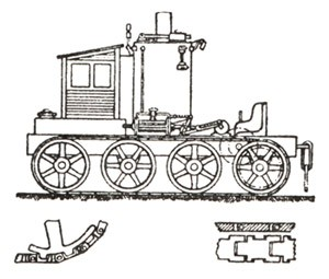
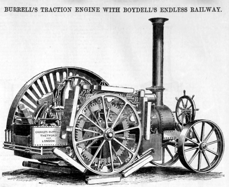
[edit]Although not a continuous track in the form encountered today, a dreadnaught wheel or "endless railway wheel" was patented by the British Engineer James Boydell in 1846. In Boydell's design, a series of flat feet are attached to the periphery of the wheel, spreading the weight.[7] A number of horse-drawn wagons, carts and gun carriages were successfully deployed in the Crimean War, waged between October 1853 and February 1856, the Royal Arsenal at Woolwich manufacturing dreadnaught wheels. A letter of recommendation was signed by Sir William Codrington, the General commanding the troops at Sebastopol.[8][9]
Boydell patented improvements to his wheel in 1854 (No. 431) – the year his dreadnaught wheel was first applied to a steam engine – and 1858 (No. 356), the latter an impracticable palliative measure involving the lifting one or other of the driving wheels to facilitate turning.
A number of manufacturers including Richard Bach, Richard Garrett & Sons, Charles Burrell & Sons and Clayton & Shuttleworth applied the Boydell patent under licence. The British military were interested in Boydell's invention from an early date. One of the objectives was to transport Mallet's Mortar, a giant 36 inch weapon which was under development, but, by the end of the Crimean War, the mortar was not ready for service. A detailed report of the tests on steam traction, carried out by a select Committee of the Board of Ordnance, was published in June 1856,[10] by which date the Crimean War was over, consequently the mortar and its transportation became irrelevant. In those tests, a Garrett engine was put through its paces on Plumstead Common. The Garrett engine featured in the Lord Mayor's show in London, and in the following month that engine was shipped to Australia. A steam tractor employing dreadnaught wheels was built at Bach's Birmingham works, and was used between 1856 and 1858 for ploughing in Thetford; and the first generation of Burrell/Boydell engines was built at the St. Nicholas works in 1856, again, after the close of the Crimean War.[11]
Between late 1856 and 1862 Burrell manufactured not less than a score of engines fitted with dreadnaught wheels. In April 1858, the journal The Engineer gave a brief description of a Clayton & Shuttleworth engine fitted with dreadnaught wheels, which was supplied not to the Western Allies, but to the Russian government for heavy artillery haulage in Crimea in the post-war period.[12][13][14] Steam tractors fitted with dreadnaught wheels had a number of shortcomings and, notwithstanding the creations of the late 1850s, were never used extensively.[9][15]
Endless Railway by John Fowler (1858)
[edit]In August 1858, more than two years after the end of the Crimean War, John Fowler filed British Patent No. 1948 on another form of "Endless Railway". In his illustration of the invention, Fowler used a pair of wheels of equal diameter on each side of his vehicle, around which pair of toothed wheels ran a 'track' of eight jointed segments, with a smaller jockey/drive wheel between each pair of wheels, to support the 'track'. Comprising only eight sections, the 'track' sections are essentially 'longitudinal', as in Boydell's initial design.[16] Fowler's arrangement is a precursor to the multi-section caterpillar track in which a relatively large number of short 'transverse' treads are used, as proposed by Sir George Caley in 1825,[17] rather than a small number of relatively long 'longitudinal' treads.
Further to Fowler's patent of 1858, in 1877, a Russian, Fyodor Blinov, created a tracked vehicle called "wagon moved on endless rails".[18] It lacked self-propulsion and was pulled by horses. Blinov received a patent for his "wagon" in 1878. From 1881 to 1888 he developed a steam-powered caterpillar-tractor. This self-propelled crawler was successfully tested and featured at a farmers' exhibition in 1896.[18]
20th century efforts
[edit]Steam traction engines were used at the end of the 19th century in the Boer Wars. But neither dreadnaught wheels nor continuous tracks were used, rather "roll-out" wooden plank roads were thrown under the wheels as required.[19] In short, whilst the development of the continuous track engaged the attention of a number of inventors in the 18th and 19th centuries, the general use and exploitation of the continuous track belonged to the 20th century, mainly in the United States and England.
A little-known American inventor, Henry Thomas Stith (1839–1916), had developed a continuous track prototype which was, in multiple forms, patented in 1873, 1880, and 1900.[20][21] The last was for the application of the track to a prototype off-road bicycle built for his son.[1] The 1900 prototype is retained by his surviving family.
Frank Beamond (1870–1941), a less-commonly known but significant British inventor, designed and built caterpillar tracks, and was granted patents for them in a number of countries, in 1900 and 1907.[22]

First commercial success (1901)
[edit]An effective continuous track was invented and implemented by Alvin Orlando Lombard for the Lombard Steam Log Hauler.[citation needed] He was granted a patent in 1901 and built the first steam-powered log hauler at the Waterville Iron Works in Waterville, Maine, the same year. In all, 83 Lombard steam log haulers are known to have been built up to 1917, when production switched entirely to internal combustion engine powered machines, ending with a Fairbanks diesel-powered unit in 1934. Alvin Lombard may also have been the first commercial manufacturer of the tractor crawler.[citation needed]
At least one of Lombard's steam-powered machines apparently remains in working order.[23] A gasoline-powered Lombard hauler is on display at the Maine State Museum in Augusta. In addition, there may have been up to twice as many Phoenix Centipede versions of the steam log hauler built under license from Lombard, with vertical instead of horizontal cylinders. In 1903, the founder of Holt Manufacturing, Benjamin Holt, paid Lombard $60,000 for the right to produce vehicles under his patent.[24]

The stiff chain by Hornsby & Sons (1904)
[edit]At about the same time a British agricultural company, Hornsby in Grantham, developed a continuous track which was patented in 1905.[25] The design differed from modern tracks in that it flexed in only one direction, with the effect that the links locked together to form a solid rail on which the road wheels ran. Hornsby's tracked vehicles were given trials as artillery tractors by the British Army on several occasions between 1905 and 1910, but not adopted.
The Hornsby tractors pioneered a track-steer clutch arrangement, which is the basis of the modern crawler operation.[citation needed] The patent was purchased by Holt.[citation needed]
-

-
 Hornsby Chain Tracked Tractor
(1907 enhanced Version)


Holt and the Caterpillar
[edit]The name Caterpillar came from a soldier during the tests on the Hornsby crawler, "trials began at Aldershot in July 1907. The soldiers immediately christened the 70bhp No.2 machine the 'caterpillar'."[26] Holt adopted that name for his "crawler" tractors. Holt began moving from steam to gasoline-powered designs, and in 1908 brought out the 40-horsepower (30 kW) "Holt Model 40 Caterpillar". Holt incorporated the Holt Caterpillar Company, in early 1910, later that year trademarked the name "Caterpillar" for his continuous tracks.[27]
Caterpillar Tractor Company began in 1925 from a merger of the Holt Manufacturing Company and the C. L. Best Tractor Company, an early successful manufacturer of crawler tractors.
With the Caterpillar D10 in 1977, Caterpillar resurrected a design by Holt and Best, the high-sprocket-drive, since known as the "High Drive",[28] which had the advantage of keeping the main drive shaft away from ground shocks and dirt,[29] and is still used in their larger dozers.
-
 Two Holt 45 gasoline crawler tractors teamed up to pull a long wagon train in the Mojave Desert during construction of the Los Angeles Aqueduct in 1909.
 -
![Caterpillar D9 High Drive. The elevated drive sprocket offers advantages to large earth-moving machines.[30]](//upload.wikimedia.org/wikipedia/commons/thumb/e/e1/Rear-D9-0002.jpg/330px-Rear-D9-0002.jpg) Caterpillar D9 High Drive. The elevated drive sprocket offers advantages to large earth-moving machines.[30]
Caterpillar D9 High Drive. The elevated drive sprocket offers advantages to large earth-moving machines.[30]

![Caterpillar D9 High Drive. The elevated drive sprocket offers advantages to large earth-moving machines.[30]](https://en.wikipedia.org/wiki/File:Rear-D9-0002.jpg)
Snow vehicles
[edit]In a memorandum of 1908, Antarctic explorer Robert Falcon Scott presented his view that man-hauling to the South Pole was impossible and that motor traction was needed.[31] Snow vehicles did not yet exist however, and so his engineer Reginald Skelton developed the idea of a caterpillar track for snow surfaces.[32] These tracked motors were built by the Wolseley Tool and Motor Car Company in Birmingham, tested in Switzerland and Norway, and can be seen in action in Herbert Ponting's 1911 documentary film of Scott's Antarctic Terra Nova Expedition.[33] Scott died during the expedition in 1912, but expedition member and biographer Apsley Cherry-Garrard credited Scott's "motors" with the inspiration for the British World War I tanks, writing: "Scott never knew their true possibilities; for they were the direct ancestors of the 'tanks' in France."[34]
-
 Snow wing skid steer with tracked treads

In time, however, a wide array of vehicles were developed for snow and ice, including ski slope grooming machines, snowmobiles, and countless commercial and military vehicles.
Military application
[edit]Continuous track was first applied to a military vehicle on the British prototype tank Little Willie. British Army officers, Colonel Ernest Swinton and Colonel Maurice Hankey, became convinced that it was possible to develop a fighting vehicle that could provide protection from machine gun fire.[35]
During World War I, Holt tractors were used by the British and Austro-Hungarian armies to tow heavy artillery and stimulated the development of tanks in several countries. The first tanks to go into action, the Mark I, built by Great Britain, were designed from scratch and were inspired by, but not directly based on, the Holt. The slightly later French and German tanks were built on modified Holt running gear.
Patent history
[edit]A long line of patents disputes who was the "originator" of continuous tracks. There were a number of designs that attempted to achieve a track laying mechanism, although these designs do not generally resemble modern tracked vehicles.[36][37][38]
In 1877 Russian inventor Fyodor Abramovich Blinov created a horse-drawn tracked vehicle called "wagon moved on endless rails",[18] which received a patent the next year. In 1881–1888 he created a steam-powered caterpillar-tractor. This self-propelled crawler was successfully tested and showed at a farmers' exhibition in 1896.[18]
According to Scientific American, Charles Dinsmoor of Warren, Pennsylvania invented a "vehicle" on endless tracks, patented as No. 351,749 on November 2, 1886.[39][40] The article gives a detailed description of the endless tracks.[41]
Alvin O. Lombard of Waterville, Maine was issued a patent in 1901 for the Lombard Steam Log Hauler that resembles a regular railroad steam locomotive with sled steerage on front and crawlers in rear for hauling logs in the Northeastern United States and Canada.[citation needed] The haulers allowed pulp to be taken to rivers in the winter. Prior to then, horses could be used only until snow depths made hauling impossible. Lombard began commercial production which lasted until around 1917 when focus switched entirely to gasoline powered machines. A gasoline-powered hauler is on display at the Maine State Museum in Augusta, Maine. After Lombard began operations, Hornsby in England manufactured at least two full length "track steer" machines, and their patent was later purchased by Holt in 1913, allowing Holt to claim to be the "inventor" of the crawler tractor.[42] Since the "tank" was a British concept it is more likely that the Hornsby, which had been built and unsuccessfully pitched to their military, was the inspiration.
In a patent dispute involving rival crawler builder Best, testimony was brought in from people including Lombard, that Holt had inspected a Lombard log hauler shipped out to a western state by people who would later build the Phoenix log hauler in Eau Claire, Wisconsin, under license from Lombard.[citation needed] The Phoenix Centipeed typically had a fancier wood cab, steering wheel tipped forward at a 45 degree angle and vertical instead of horizontal cylinders.
-
-
 A working model of the original Hornsby & Sons tracked tractor


Linn
[edit]In the meantime, a gasoline-powered motor home was built by Lombard for Holman Harry (Flannery) Linn of Old Town, Maine to pull the equipment wagon of his dog & pony show, resembling a trolley car only with wheels in front and Lombard crawlers in rear. Linn had experimented with gasoline and steam-powered vehicles and six-wheel drive before this, and at some point entered Lombard's employment as a demonstrator, mechanic and sales agent. This resulted in a question of proprietorship of patent rights after a single rear-tracked gasoline-powered road engine of tricycle arrangement was built to replace the larger motor home in 1909 on account of problems with the old picturesque wooden bridges. This dispute resulted in Linn departing Maine and relocating to Morris, New York, to build an improved, contour following flexible lag tread or crawler with independent suspension of halftrack type, gasoline and later diesel powered. Although several were delivered for military use between 1917 and 1946, Linn never received any large military orders. Most of the production between 1917 and 1952, approximately 2500 units, was sold directly to highway departments and contractors. Steel tracks and payload capacity allowed these machines to work in terrain that would typically cause the poorer quality rubber tyres that existed before the mid-1930s to spin uselessly, or shred completely.[citation needed]
Linn was a pioneer in snow removal before the practice was embraced in rural areas, with a nine-foot steel v-plow and sixteen foot adjustable leveling wings on either side. Once the highway system became paved, snowplowing could be done by four wheel drive trucks equipped by improving tyre designs, and the Linn became an off highway vehicle, for logging, mining, dam construction, arctic exploration, etc.[citation needed]
Engineering
[edit]-
 Diagram of tracked suspension: (1=rear drive wheel (rear wheel drive), 2=track, 3=return rollers, 4=front drive wheel (front wheel drive), 5=road wheels, 6=idler)
 -

.png)

Construction and operation
[edit]Modern tracks are built from modular chain links which together compose a closed chain. The links are jointed by a hinge, which allows the track to be flexible and wrap around a set of wheels to make an endless loop. The chain links are often broad, and can be made of manganese alloy steel for high strength, hardness, and abrasion resistance.[43]
Track construction and assembly is dictated by the application. Military vehicles use a track shoe that is integral to the structure of the chain in order to reduce track weight. Reduced weight allows the vehicle to move faster and decreases overall vehicle weight to ease transportation. Since track weight is completely unsprung, reducing it improves suspension performance at speeds where the track's momentum is significant. In contrast, agricultural and construction vehicles opt for a track with shoes that attach to the chain with bolts and do not form part of the chain's structure. This allows track shoes to break without compromising the ability of the vehicle to move and decrease productivity but increases the overall weight of the track and vehicle.
The vehicle's weight is transferred to the bottom length of track by a number of road wheels, or sets of wheels called bogies. While tracked construction equipment typically lacks suspension due to the vehicle only moving at low speeds, in military vehicles road wheels are typically mounted on some form of suspension to cushion the ride over rough ground. Suspension design in military vehicles is a major area of development; the very early designs were often completely unsprung. Later-developed road wheel suspension offered only a few inches of travel using springs, whereas modern hydro-pneumatic systems allow several feet of travel and include shock absorbers. Torsion-bar suspension has become the most common type of military vehicle suspension. Construction vehicles have smaller road wheels that are designed primarily to prevent track derailment and they are normally contained in a single bogie that includes the idler-wheel and sometimes the sprocket.
-
 Overlapped and interleaved road wheels of a German Tiger I heavy tank
 -
 An Sd.Kfz. 11's half-track units, showing the rims of its six Schachtellaufwerk overlapped/interleaved roadwheel sets for each track unit per side

.jpg)
Overlapping road wheels
[edit]Many World War II German military vehicles, initially (starting in the late 1930s) including all vehicles originally designed to be half-tracks and all later tank designs (after the Panzer IV), had slack-track systems, usually driven by a front-located drive sprocket, the track returning along the tops of a design of overlapping and sometimes interleaved large diameter road wheels, as on the suspension systems of the Tiger I and Panther tanks, generically known by the term Schachtellaufwerk (interleaved or overlapping running gear) in German, for both half-track and fully tracked vehicles. There were suspensions with single or sometimes doubled wheels per axle, alternately supporting the inner and outer side of the track, and interleaved suspensions with two or three road wheels per axle, distributing the load over the track.[44]
The choice of overlapping/interleaved road wheels allowed the use of slightly more transverse-orientation torsion bar suspension members, allowing any German tracked military vehicle with such a setup to have a noticeably smoother ride over challenging terrain, leading to reduced wear, ensuring greater traction and more accurate fire. However, on the Russian front, mud and snow would become lodged between the overlapping wheels, freeze, and immobilize the vehicle. As a tracked vehicle moves, the load of each wheel moves over the track, pushing down and forward that part of the earth or snow underneath it, similarly to a wheeled vehicle but to a lesser extent because the tread helps distribute the load. On some surfaces, this can consume enough energy to slow the vehicle down significantly. Overlapped and interleaved wheels improve performance (including fuel consumption) by loading the track more evenly. It also must have extended the life of the tracks and possibly of the wheels.[citation needed] The wheels also better protect the vehicle from enemy fire, and mobility is improved when some wheels are missing.
This relatively complicated approach has not been used since World War II ended. This may be related more to maintenance than to original cost. The torsion bars and bearings may stay dry and clean, but the wheels and tread work in mud, sand, rocks, snow, and other surfaces. In addition, the outer wheels (up to nine of them, some double) had to be removed to access the inner ones. In WWII, vehicles typically had to be maintained for a few months before being destroyed or captured[citation needed], but in peacetime, vehicles must train several crews over a period of decades.
Drive train
[edit]Transfer of power to the track is accomplished by a drive wheel, or drive sprocket, driven by the motor and engaging with holes in the track links or with pegs on them to drive the track. In military vehicles, the drive wheel is typically mounted well above the contact area on the ground, allowing it to be fixed in position. In agricultural crawlers it is normally incorporated as part of the bogie. Placing suspension on the sprocket is possible, but is mechanically more complicated. A non-powered wheel, an idler, is placed at the opposite end of the track, primarily to tension the track, since loose track could be easily thrown (slipped) off the wheels. To prevent throwing, the inner surface of the track links usually have vertical guide horns engaging grooves, or gaps between the doubled road and idler/sprocket wheels. In military vehicles with a rear sprocket, the idler wheel is placed higher than the road wheels to allow it to climb over obstacles. Some track arrangements use return rollers to keep the top of the track running straight between the drive sprocket and idler. Others, called slack track, allow the track to droop and run along the tops of large road wheels. This was a feature of the Christie suspension, leading to occasional misidentification of other slack track-equipped vehicles.
Steering
[edit]Continuous track vehicles steer by applying more or less drive torque to one side of the vehicle than the other, and this can be implemented in a variety of ways.
"Live" and "dead" track
[edit]Tracks may be broadly categorized as live or dead track. Dead track is a simple design in which each track plate is connected to the rest with hinge-type pins. These dead tracks will lie flat if placed on the ground; the drive sprocket pulls the track around the wheels with no assistance from the track itself. Live track is slightly more complex, with each link connected to the next by a bushing which causes the track to bend slightly inward. A length of live track left on the ground will curl upward slightly at each end. Although the drive sprocket must still pull the track around the wheels, the track itself tends to bend inward, slightly assisting the sprocket and somewhat conforming to the wheels.
Rubber track pads
[edit]Tracks are often equipped with rubber pads to improve travel on paved surfaces more quickly, smoothly and quietly. While these pads slightly reduce a vehicle's cross-country traction, they prevent damage to any pavement. Some pad systems are designed to remove easily for cross-country military combat.
-
 Small tracks on a roadworks machine. Note the rubber pads to reduce wear on the carriageway.
 -
 Worn and new track pads on an M1 Abrams main battle tank
 -
 Rubber tracks (Case IH 8240)
 -
 Tracked vehicles long-distance hauling on equipment trailers


Rubber tracks
[edit]Starting from late 1980s, many manufacturers provide rubber tracks instead of steel, especially for agricultural applications. Rather than a track made of linked steel plates, a reinforced rubber belt with chevron treads is used.
In comparison to steel tracks, rubber tracks are lighter, waste less power on internal friction, make less noise and do not damage paved roads. However, they impose more ground pressure below the wheels, as they are not able to equalize pressure as well as the stiff mechanism of track plates, especially the spring loaded live tracks. Another disadvantage is that they are not disassemblable into tracks and therefore cannot be repaired, having to be discarded as whole if once damaged.
Previous belt-like systems, such as those used for half-tracks in World War II, were not as strong, and during military actions were easily damaged. The first rubber track was invented and constructed by Adolphe Kégresse and patented in 1913; in historic context rubber tracks are often called Kégresse tracks. First rubber-tracked agricultural tractor was the Oliver Farm Equipment HGR from 1945-1948, which was ahead of its time and only saw small-scale production.
Advantages
[edit]- Tracked vehicles are much less likely than wheeled vehicles to get stuck in soft ground, mud or snow, since the tracks distribute the weight of the vehicle over a larger contact area, decreasing its ground pressure. The seventy-ton M1 Abrams tank has an average ground pressure of just over 15 psi (100 kPa). Since tyre air pressure is approximately equal to average ground pressure, a typical car will have an average ground pressure of 28 psi (190 kPa) to 33 psi (230 kPa).
- Tracked vehicles have better mobility over rough terrain than those with wheels: they smooth out the bumps, glide over small obstacles and are capable of crossing trenches or breaks in the terrain. Riding in a fast tracked-vehicle feels just like riding in a boat over heavy swells.
- The larger contact area, coupled with the cleats, or grousers, on the track shoes, allows vastly superior traction that results in a much better ability to push or pull large loads where wheeled vehicles would dig in. Bulldozers, which are most often tracked, use this attribute to rescue other vehicles (such as wheel loaders) which have become stuck in, or sunk into, the ground.
- Tracks cannot be punctured or torn and are more resilient in military combat. Should a track be broken, it often can be repaired immediately using special tools and spare parts, without the need for special facilities; this may be crucial in combat situations.
Disadvantages
[edit]
The disadvantages of tracks are lower top speed, much greater mechanical complexity, shorter life and the damage that their all-steel versions cause to the surface on which they pass: They often cause damage to less firm terrain such as lawns, gravel roads, and farm fields, as the sharp edges of the track easily rout the turf. Accordingly, vehicle laws and local ordinances often require rubberised tracks or track pads. A compromise between all-steel and all-rubber tracks exists: attaching rubber pads to individual track links ensures that continuous track vehicles can travel more smoothly, quickly, and quietly on paved surfaces. While these pads slightly reduce a vehicle's cross-country traction, in theory they prevent damage to any pavement.
Additionally, the loss of a single segment in a track immobilizes the entire vehicle, which can be a disadvantage in situations where high reliability is important. Tracks can also ride off their guide wheels, idlers or sprockets, which can cause them to jam or to come completely off the guide system (this is called a "thrown" track). Jammed tracks may become so tight that the track may need to be broken before a repair is possible, which requires either explosives or special tools. Multi-wheeled vehicles, for example, 8 X 8 military vehicles, may often continue driving even after the loss of one or more non-sequential wheels, depending on the base wheel pattern and drive train.
Prolonged use places enormous strain on the drive transmission and the mechanics of the tracks, which must be overhauled or replaced regularly. It is common to see tracked vehicles such as bulldozers or tanks transported long distances by a wheeled carrier such as a tank transporter or train, though technological advances have made this practice less common among tracked military vehicles than it once was[citation needed].
Gallery
[edit]-
 Komatsu CD-110R
 -
 German World War II-era SdKfz 251 military halftrack, with overlapped interleaved wheels and "slack track"
 -
 Experimental four-track tank (Obyekt 279)
 -
 Soviet T-55 tank with "slack track" and rear drive sprocket
 -

-
 Track of a Leclerc tank
 -
 Experimental tracked landing gear on a B-36 Peacemaker


Current manufacturers
[edit]The pioneer manufacturers have been replaced mostly by large tractor companies such as AGCO, Liebherr Group,[45] John Deere, Yanmar, New Holland, Kubota,[46] Case, Caterpillar Inc., CLAAS.[47] Also, there are some crawler tractor companies specialising in niche markets. Examples are Otter Mfg. Co. and Struck Corporation.,[48] with many wheeled vehicle conversion kits available from the American Mattracks firm of Minnesota since the mid-1990s.
Russian off-road vehicles are built by companies such as ZZGT[49] and Vityaz.[50]
In nature
[edit]- Navicula diatoms are known for their ability to creep about on each other and on hard surfaces such as microscope slides. It is thought that around the outside of the navicula's shell is a girdle of protoplasm that can flow and thus act as a continuous track.
See also
[edit]References
[edit]- ^ a b "The Tank Tread Was His Baby". Popular Science (June): 63. 1944. Archived from the original on 2017-03-13. Retrieved 2011-08-24.
- ^ "Sir George Cayley's patent universal railway". Mechanics Magazine. 5 (127): 225–227. 1826-01-28. Archived from the original on 2017-03-13.
- ^ "Josef-Maria Hoëné de Wronski". Archived from the original on 2009-08-11. Retrieved 2009-05-30.
- ^ "Heathcote's Steam Plough". Chelmsford Chronicle. US. 29 December 1837. p. 4.
- ^ Classic Caterpillar Crawlers. MotorBooks International. 2001. ISBN 9781610605793.
- ^ Brown, Jonathan (2008). Steam on the Farm: A History of Agricultural Steam Engines 1800 to 1950. Crowood Press. ISBN 9781847970527.
- ^ "Burrell's traction engine with Boydell's endless railway". Grace's Guide. 1857. Archived from the original on 2013-10-02. Retrieved 2013-09-30.
- ^ Lane, Michael R. (1994). The story of the St. Nicholas Works: A History of Charles Burrell and Sons. London: Unicorn Press. ISBN 978-0906290071.
- ^ a b "Boydell Artillery Wheel" (PDF). Archived (PDF) from the original on 2013-10-02. Retrieved 2013-09-30.
- ^ "Governments Experiments with Boydell's Traction-Engine". The Farmer's Magazine. 45 (1). London. 1856-06-30. Archived from the original on 2016-03-04.
- ^ "Tuxford's Boydell Traction Engine" (PDF). Science& Society: Picture Library. UK. 1857. Archived (PDF) from the original on 2016-03-04. Retrieved 2014-02-04.
- ^ (Staff) (23 April 1858). "The iron, coal, and general trades of Birmingham, Wolverhampton, and other towns". The Engineer. 5: 327–328. See p. 328, left-hand column.
- ^ Lane (1994).
- ^ Clark, Ronald H. (1974). The Development of the English Traction Engine. Cambridge UK: Goose and Son. ISBN 0900404027.
- ^ "Charles Burrell & Sons Limited" (PDF). University of Reading. UK. Archived (PDF) from the original on 2014-02-21. Retrieved 2013-09-30.
- ^ "Burrell-Boydell Tractor" (PDF). Archived (PDF) from the original on 2013-10-02. Retrieved 2013-09-30.
- ^ Caley, Georg (1825). "Patent No. 5260 A New Locomotive Apparatus" (PDF). Archived (PDF) from the original on 2017-11-21. Retrieved 2013-09-30.
- ^ a b c d Lozovoi, D.; Lozova, A. "Изобретатель трактора (Ф. Блинов)" [The inventor of the tractor (F.Blinov)]. Russia in Colours (in Russian). Archived from the original on 2011-07-27. Retrieved 2011-08-24.
- ^ The Implement and Machinery Review, 1901-01-02
- ^ Henry T. Stith's patents for tracked wheels:
- Stith, Henry T. "Improvement in traction-wheels" U.S. Patent no. 138,707 (filed: 2 May 1873; issued: 6 May 1873).
- Stith, Henry T. "Traction-wheel" Archived 2021-08-12 at the Wayback Machine U.S. Patent no. 224,741 (filed: 5 August 1879; issued: 17 February 1880).
- Stith, Henry T. "Traction wheel" Archived 2021-08-12 at the Wayback Machine U.S. Patent no. 654,291 (filed: 26 December 1899; issued: 24 July 1900).
- ^ Biographical information about the American inventor Henry Thomas Stith (1839-1916) is available from the Kansas Historical Society.
- ^ "Invention of the Caterpillar Track: Frank Beamond and his Patents" (PDF). Archived (PDF) from the original on 2015-07-21. Retrieved 2014-12-10.
- ^ "Lombard Log Hauler and Model T Snowmobile Show Route 175 Thornton, NH". Archived from the original on 2011-08-14. Retrieved 2011-08-24.
- ^ Backus, Richard (August–September 2004). "100 Years on Track 2004 Tulare Antique Farm Equipment Show". Farm Collector. Gas Engine Magazine. Archived from the original on 2009-08-22. Retrieved 2010-02-04.
- ^ GB 190416345, David Roberts, "Improvements in or connected with Road Locomotives and Vehicles.", published 1 Jun 1905 Archived 23 November 2021 at the Wayback Machine
- ^ The Devil's Chariots, John Glanfield
- ^ "About Caterpillar". Antique Caterpillar Machinery Owners Club. Archived from the original on 2016-03-22. Retrieved 2016-11-07.
- ^ Haddock, Keith. Giant Earthmovers: An Illustrated History. MotorBooks International. pp. 17, 20, 21. ISBN 9781610605861. Archived from the original on 2015-10-07. Retrieved 2015-08-16.
- ^ The Earthmover Encyclopedia, Page 28, Keith Haddock
- ^ "Cat's elevated sprocket that changed the dozer market". Equipment Journal. 2017-09-17. Archived from the original on 2021-05-18. Retrieved 2019-04-16.
- ^ R. F. Scott (1908). The Sledging Problem in the Antarctic, Men versus Motors
- ^ Roland Huntford (2003) Scott and Amundsen. Their Race to the South Pole. The Last Place on Earth. Abacus, London, p.224
- ^ riverbanksy (2011-08-21). 90 Degrees South. Archived from the original on 2016-10-03. Retrieved 2016-10-23 – via YouTube.
- ^ Cherry-Garrard, Apsley (1922). The Worst Journey in the World. Vol. 2. London, England: Constable & Co. Ltd. p. 322. Archived from the original on 2021-08-12. Retrieved 2021-08-12.
- ^ Simkin, John. "Little Willie Tank". UK: Spartacus Educational. Archived from the original on 2016-11-09. Retrieved 2016-11-08.
- ^ US patent 69987, James K Glen, "Improvement in Motive Power", issued 1867-10-22
- ^ US patent 373887, William Fender, "Wheel With Endless Rail", issued 1887-11-29
- ^ US patent 433488, Goldsbury Harden Pond, "Traction Engine", issued 1890-08-05
- ^ Kane, Joseph Nathan, Famous First Facts, H. W. Wilson Company (1950), p. 47
- ^ US patent 351749, Charles Dinsmoor, "Vehicle", issued 1886-11-02 A design for a tracked vehicle.
- ^ Scientific American, December 18, 1886, Vol. LV, No. 25
- ^ "Caterpillar Tractor Co. List of Deals". Lehman Brothers Collection. President and Fellows of Harvard College. 2010. Archived from the original on 2010-06-29. Retrieved 2010-11-06.
In 1925 Holt and C.W. Best's company merged to form the Caterpillar Tractor Company.
- ^ "Austenitic Manganese Steels". Archived from the original on 2012-03-08. Retrieved 2011-08-24.
- ^ Peter Chamberlain and Hilary Doyle, Encyclopedia of German Tanks of World War II, 1999
- ^ "Official website". Liebherr. Archived from the original on 2006-10-14. Retrieved 2013-05-03.
- ^ "Kubota crawler tractor". Kubota.com. 2008-07-14. Archived from the original on 2012-03-14. Retrieved 2013-05-03.
- ^ "Search results for Used Tracked tractors". Mascus.co.uk. Archived from the original on 2013-06-02. Retrieved 2013-05-03.
- ^ Burner, Ken (1997). "The Small Tractor FAQ – Tractor Resources". Carnegie Mellon University. Archived from the original on 2012-06-22.
- ^ "The Zavolzhsky Crawler Vehicle Plant". Russia: Zavolzhsky Crawler Vehicle Plant. Archived from the original on 2013-11-27. Retrieved 2016-11-07.
- ^ "Main". Russia: Vityaz machine-building company. Archived from the original on 2016-10-22. Retrieved 2016-11-07.
External links
[edit]- Scale model of Hornsby Chain Tractor at 2005 Harrogate Model Engineering Show
- Dedication to the only commercially-sold Hornsby caterpillar crawler
- Hornsby Steam Chain Tractor website
Video clips
[edit]- Hornsby Chain Tractor Promotion-Video (6:17, 1908) (British Film Institute)
- Scale Model Hornsby Traktor (Stapleford Steam, Leicestershire, 2008)
- 1/3 Scale Hornsby Traktor
