

Community hub
Recent from talks
Contribute something
Nothing was collected or created yet.
Railway coupling
View on Wikipedia| Part of a series on |
| Rail transport |
|---|
|
|
| Infrastructure |
|
|
| Rolling stock |
|
|
| Urban rail transit |
|
|
| Other topics |
|
|

A coupling or coupler is a mechanism, typically located at each end of a rail vehicle, that connects them together to form a train. The equipment that connects the couplers to the vehicles is the draft gear or draw gear, which must absorb the stresses of the coupling and the acceleration of the train.
Throughout the history of rail vehicles, a variety of coupler designs and types have been developed worldwide. Key design considerations include strength, reliability, easy and efficient handling, and operator safety. Automatic couplers engage automatically when the cars are pushed together. Modern versions not only provide a mechanical connection, but can also couple brake lines and data lines.
Different countries use different types of couplers. While North American railroads and China use Janney couplers, railroads in the former Soviet Union use SA3 couplers and the European countries use Scharfenberg and screw couplers. Challenges and complications arise when coupling vehicles with different couplers. Barrier cars, also called match cars, cars with dual couplers, or adapters are used to accomplish this task.
Nomenclature
[edit]Compatible and similar couplings or couplers are frequently referred to using widely differing make, brand, or regional names, or nicknames, which can make describing standard or typical designs confusing. Dimensions and ratings noted in these articles are usually of nominal or typical components and systems, though standards and practices also vary widely with railway, region, and era.
Buff: when the consist (one or more cars coupled together) of cars is in compression; opposite of tension.[1]
Buffers and chain
[edit]The basic type of coupling on railways following the British tradition is the buffer and chain coupling. A large chain of three links connects hooks on the adjoining wagons. These couplings followed earlier tramway practice but were made more regular. Buffers on the frame of the wagon absorbed impact loads, as the train overran a slowing locomotive.
The simple chain could not be tensioned, and this loose coupling allowed a great deal of back and forth movement and bumping between cars, as well as jarring when trains started. While acceptable for mineral cars, this coupling made for an uncomfortable ride in passenger coaches, so the chain was improved by replacing the center link with a screw with a left-hand thread on one side and a right-hand thread on the other. In the center of the screw is the handle housing with a hinged ball handle attached. This turnbuckle style arrangement allows the vehicles to be pulled together by tightening the screw with the attached handle. Typically, the screw is tightened until there are two threads left next to the handle housing. A support is attached to the trunnion nut on the coupling link side to rest the handle of the screw to prevent loosening of the screw while the coupling is in use. The official name of this type of coupling is screw coupling or UIC coupling according to the European standard EN 15566 Draw gear and screw coupling.
A simplified version of this, quicker to attach and detach, still used three links but with the centre link given a T-shaped slot. This could be turned lengthwise to lengthen it, allowing coupling, then turned vertically to the shorter slot position, holding the wagons more tightly together.
Higher speeds associated with fully fitted freight[a] made the screw-tensioned form a necessity.
The earliest 'dumb buffers' were fixed extensions of the wooden wagon frames, but later spring buffers were introduced. The first of these were stiff cushions of leather-covered horsehair, later steel springs and then hydraulic damping.
This coupling is still widespread in Western and Central Europe and in parts of Northern Africa, the Middle East and South Asia.[2]
-
 Three-link coupling on an antique tank wagon
 -
 UIC standard screw coupling, shown attached and tightened


Link and pin
[edit]

.jpg)
The link-and-pin coupling was the original style of coupling used on North American railways. After most railroads converted to semi-automatic Janney couplers, the link-and-pin survived on forest railways. While simple in principle, the system suffered from a lack of standardisation regarding size and height of the links, and the size and height of the pockets.
The link-and-pin coupler consisted of a tube-like body that received an oblong link. During coupling, a rail worker had to stand between the cars as they came together and guide the link into the coupler pocket. Once the cars were joined, the employee inserted a pin into a hole a few inches from the end of the tube to hold the link in place. This procedure was exceptionally dangerous and many brakemen lost fingers or entire hands when they did not get them out of the way of the coupler pockets in time. Many more were killed as a result of being crushed between cars or dragged under cars that were coupled too quickly. Brakemen were issued with heavy clubs that could be used to hold the link in position, but many brakemen would not use the club, and risked injury.
The link-and-pin coupler proved unsatisfactory because:
- It made a loose connection between the cars, with too much slack action.
- There was no standard design, and train crews often spent hours trying to match pins and links while coupling cars.
- Crew members had to go between moving cars during coupling, and were frequently injured and sometimes killed.
- The links and pins were often pilfered due to their value as scrap metal, resulting in substantial replacement costs.
- When a car happened to be turned 180 degrees one would have to look for a link.
- Railroads progressively began to operate trains that were heavier than the link-and-pin system could cope with.
In Britain link-and-pin couplers were common on narrow gauge industrial and military railways, and eventually evolved into a form that could be reliably coupled when the train was stationary.
The Panama Canal mules, the locomotives used to guide the ships through the locks of the Panama Canal, have link and pin couplers and side buffers. This design was chosen so that these normally solo operating locomotives could be coupled to another locomotive in the event of a breakdown. On straight track, the link and pin coupler is used. Since the vertical curve between the straight track sections and the ramp between the lock chambers has a very small radius, the difference in height would be too great for a link and pin coupler, so the locomotives must be pushed through these sections uncoupled by using the side buffers. They have an extra high buffer plate to prevent the buffers from buffer-locking in tight vertical curves.
Balance lever coupling
[edit]
The balance lever coupling, also central buffer coupling with two screw coupling, is a coupler commonly used on narrow gauge railroads with tight curves. By swapping the pulling and pushing devices, the standard screw coupling used on standard gauge railroads became a center buffer coupling with one screw coupling on each side of the buffer. The screw couplers are connected to a compensating lever that pivots on a vertical trunnion on the center buffer rod, allowing an even distribution of tractive forces between the two screw couplers.[3]
Albert coupler
[edit]
To avoid safety issues, Karl Albert, then director at the Krefeld Tramway, developed the Albert coupler during 1921. The Albert coupler was created as a key and slot coupler with two pins. Vehicles to be coupled were pushed together, both couplings moving to the same side. One pin was inserted, then the vehicles were pulled to straighten the coupling and the other pin inserted. This operation required less exact shunting. Due to the single-piece design, only minimal slack was possible. The system became quite popular with tram systems and narrow gauge lines.
During the 1960s most cities replaced them with automatic couplers. But even in modern vehicles, Albert couplers get installed as emergency couplers for towing a faulty vehicle.
Miller hook and platform
[edit]The link and pin was replaced in North American passenger car usage during the latter part of the 19th century by the assemblage known as the Miller platform, which included a new coupler called the Miller hook.[4] The Miller platform (and hook coupler) was used for several decades before being replaced by the Janney coupler.
Norwegian
[edit]
The Norwegian coupler consists of a central buffer with a movable hook that drops into a slot in the central buffer.[5] There may also be a U-shaped safety catch on the opposite buffer that is flipped over the top of the hook to secure it. The safety device may also be a chain with a ball-shaped weight at the end that is thrown over the hook to hold it in place.[5] On railways where the rolling stock always face the same direction, the mechanical hook can be on one end of the wagon only. Not all Norwegian couplers are compatible with one another as they vary in height and width, and may or may not be limited to one hook at a time. The traction force limit is typically 350 kN.[6] Sometimes the Norwegian coupler is supplemented with auxiliary chains.
The Norwegian coupler is also known as the Lloyd coupler named after its British manufacturer F.H. Lloyd & Co. Ltd near Wednesbury or as the meat chopper coupler named after the shape of the movable hook. The Norwegian coupler allows sharper curves than the buffer and chain coupler, which is an advantage on narrow gauge railways where low speeds and reduced train loads allow a simpler system. The Norwegian coupler is found only on narrow gauge railways of 1,067 mm (3 ft 6 in), 1,000 mm (3 ft 3+3⁄8 in) or less in Great Britain and its former colonies. For example, it is used on the Isle of Man Railway, the Western Australian Government Railways, in Tanzania, on the Ffestiniog Railway, on the Lynton and Barnstaple Railway, and on the Welsh Highland Railway,
Radial couplers
[edit]Two versions of radial coupler were used in South Africa. One, the Johnston coupler, commonly known as a bell link-and-pin coupler, was introduced in 1873 and is similar in operation to and compatible with link-and-pin couplers, but bell-shaped with a circular coupler face. The other, the bell-and-hook coupler, was introduced in 1902 and is similar to the Norwegian coupler, but also with a circular coupler face and with a coupler pocket which is open at the top of the coupler face to accommodate the drawhook.[7]
Johnston coupler
[edit]
The Johnston coupler, commonly known as a bell link-and-pin coupler from its bell shape, was first introduced in the Cape of Good Hope in 1873, following the establishment of the Cape Government Railways (CGR) in 1872 and the decision by the Cape government to expand the railways into the interior and to convert the existing tracks from 4 ft 8+1⁄2 in (1,435 mm) standard gauge to 3 ft 6 in (1,067 mm) Cape gauge. All new Cape gauge locomotives and rolling stock acquired from 1873 were equipped with these or similar couplers, beginning with the CGR 0-4-0ST of 1873, a construction locomotive named Little Bess.[8][9][10]
The Natal Government Railways (NGR), established in the Colony of Natal in 1875, followed suit and all locomotives and rolling stock acquired by that railway were equipped with Johnston couplers, beginning with the NGR Class K 2-6-0T in 1877.[11][12]
Likewise, in 1889, when the first locomotives were obtained by the newly established Netherlands-South African Railway Company in the Zuid-Afrikaansche Republiek, they were fitted with Johnston couplers.[9][13]
Unlike the 2 ft (610 mm) narrow gauge railways of the CGR, those of the NGR also made use of Johnston couplers. The first of these narrow gauge lines came into operation in 1906, when the first NGR Class N 4-6-2T locomotives entered service on the Weenen branch out of Estcourt.[10][14]
Coupling and uncoupling were done manually, which posed a high risk of serious injury or death to crew members, who had to go between moving vehicles to guide the link into the coupler pocket during coupling. Johnston couplers gradually began to be replaced on the South African Railways from 1927, but not on narrow gauge rolling stock. All new Cape gauge locomotives and rolling stock acquired from that year were equipped with AAR knuckle couplers. Conversion of all older rolling stock was to take several years and both coupler types could still be seen on some vehicles into the late 1950s. During the transition period, knuckle couplers on many locomotives had a horizontal gap and a vertical hole in the knuckle itself to accommodate, respectively, a link and a pin, to enable it to couple to vehicles which were still equipped with the older Johnston couplers.[9][15]
Bell-and-hook coupler
[edit]The bell-and-hook coupling system was first introduced in the Cape of Good Hope in 1902, when two CGR Type A 2-6-4T locomotives were acquired as construction engines on the new 2 ft (610 mm) narrow gauge Avontuur Railway which was being constructed out of Port Elizabeth through the Langkloof. In South Africa, these couplers were used on only the narrow gauge lines in the Cape of Good Hope.[7][10][16][17]
The coupler is similar to the Norwegian coupler. It is a radial coupler with a coupler pocket which is open at the top of the coupling face. Instead of a link and pins, it makes use of a drawhook which, upon coupling, slides over the drawhook pin in the coupler of the next vehicle in the train. To prevent the drawhook of the mating coupler from accidental uncoupling, the coupler bell is equipped with a drawhook guard, commonly known as a bridle, above the coupler pocket.[7]
Usual practice was to have a drawhook fitted to only one of the mating couplers and train crews therefore carried spare drawhooks and drawhook pins on the locomotive. While automatic coupling is possible, this rarely happens and manual assistance is required during coupling. Uncoupling is done manually by lifting the drawhook by hand to release it. The coupler could be adapted to be compatible with the Johnston coupler by replacing the drawhook with a U-shaped adapter link, which was attached using the same drawhook pin.[7]
Bell-and-hook couplers began to be replaced on the Avontuur Railway upon the introduction of Class 91-000 diesel-electric locomotives on the narrow gauge system in 1973. All new narrow gauge rolling stock acquired for that line from that year were equipped with Willison couplers. Older rolling stock were not converted and an adapter was used to enable coupling between the two types. The drawhook on the bell-and-hook coupler would be replaced with the adapter, which was attached using the same drawhook pin.[7]
-
 Bell-and-hook coupler
 -
 Bell-and-hook coupler with Willison adapter
 -
 Willison coupler adapter for bell-and-hook couplers
 -
 Bell-and-hook coupler with Johnston coupler adapter link instead of a hook


Automatic couplers
[edit]There are a number of automatic train couplings, most of which are mutually incompatible. The level of automation varies and can be divided into categories:
- mechanical coupling of vehicles only, requires manual connection of pneumatic and electrical lines;
- mechanical coupling of vehicles with automatic connection of pneumatic lines, requires manual connection of electrical lines;
- mechanical coupling of vehicles with automatic connection of pneumatic and electrical lines (but not data transmission lines);
- mechanical coupling of vehicles with automatic connection of pneumatic and electrical lines (including data transmission lines);
- mechanical coupling of vehicles with automatic connection of pneumatic and electrical lines (including data transmission lines) and automatic uncoupling capability.[18]
Buckeye/Janney/MCB/ARA/AAR/APTA couplers
[edit]


Lower electric connector is not typical in North America.
The Janney coupler, later the Master Car Builders Association (MCB) coupler,[19] now the Association of American Railroads (AAR) coupler, is also commonly known as a buckeye, knuckle, or Alliance coupler. The AAR/APTA TypeE, TypeF, and TypeH couplers are all compatible Janney couplers, but used for different rail cars (general freight, tank cars, rotary hoppers, passenger, etc.).
The knuckle coupler or Janney coupler was invented by Eli H. Janney, who received a patent in 1873 (U.S. patent 138,405).[20] It is also known as a buckeye coupler, notably in the United Kingdom, where some rolling stock (mostly for passenger trains) is fitted with it. Janney was a dry goods clerk and former Confederate Army officer from Alexandria, Virginia, who used his lunch hours to whittle from wood an alternative to the link and pin coupler. The term buckeye comes from the nickname of the US state of Ohio, the "Buckeye State" and the Ohio Brass Company which originally marketed the coupling.[21][22]
In 1893, satisfied that an automatic coupler could meet the demands of commercial railroad operations and, at the same time, be manipulated safely, the United States Congress passed the Safety Appliance Act. Its success in promoting switchyard safety was stunning. Between 1877 and 1887, approximately 38% of all railworker accidents involved coupling. That percentage fell as the railroads began to replace link and pin couplers with automatic couplers. By 1902, only two years after the SAA's effective date, coupling accidents constituted only 4% of all employee accidents. Coupler-related accidents dropped from nearly 11,000 in 1892 to just over 2,000 in 1902, even though the number of railroad employees steadily increased during that decade.
When the Janney coupler was chosen to be the North American standard, there were 8,000 patented alternatives to choose from. Many AAR coupler designs exist to accommodate requirements of various car designs, but all are required to have certain dimensions in common which allow for one design to couple to any other.[23]
The Janney coupler is used in the United States, Canada, Mexico, Japan, India, Taiwan, Australia, New Zealand, South Africa, Saudi Arabia, Cuba, Chile, Brazil, Portugal, China and many countries in Africa both standard gauge and narrow gauges.
The Janney coupler generally provides only mechanical coupling, only Type H adds automatic connections of pneumatic and electrical lines.[24]
Changes since 1873
[edit]Bazeley coupler
[edit]Henricot coupler
[edit]The Henricot coupler is a variation on the Janney coupler, introduced by Belgian engineer and entrepreneur Émile Henricot of Court-Saint-Étienne. It is used on certain EMUs of the National Railway Company of Belgium, including the Class 75).
- Henricot couplers
-

-
 Henricot coupler on a Belgian EMU
 -
 Closeup of Henricot coupler


Willison/SA3 coupler
[edit]
An animation of the SA-3 coupler

The Willison coupler was developed in the US in 1916 to address issues present in the Janney coupling.[25]
The Russian SA3 coupler works according to the same principles as the AAR coupler, but the two types are incompatible.[26] It was introduced in the Soviet Union in 1932 based on a British patent and has since been used on the whole 1,520 mm (4 ft 11+27⁄32 in) network, including Mongolia. Finnish locomotives have Unilink couplers that can couple to UIC couplers used in Finnish stock and SA3 couplers used in Russian stock.
It is also used on the 1,435 mm (4 ft 8+1⁄2 in) standard gauge networks of Iran and on Malmbanan in Sweden for ore trains. Some 2 ft (610 mm) gauge cane tramway vehicles in Queensland have been fitted with miniature Willison couplers.[27] It was introduced on the 2 ft (610 mm) narrow-gauge Avontuur Railway of the South African Railways in 1973.[7]
- Russian trains are rarely longer than about 750 m (2,461 ft)[citation needed] and rarely exceed a maximum tonnage of about 6,000 t (5,900 long tons; 6,600 short tons)[citation needed]. The heaviest trains using these couplers are on Malmbanan where they are up to 9,000 t (8,900 long tons; 9,900 short tons).[28]
- Maximum force the SA3 coupler can carry, both tensile and compressive, is about 2.5 MN (280 STf; 250 LTf).[29]
- The maximum allowed tractive effort for the SA-3 is 135 tf (1,320 kN; 133 LTf; 149 STf) (1.32 MN or 300,000 lbf) by Russian white papers.[citation needed]
- The proposed European automatic coupler is compatible with the Russian coupler but with automatic air, control and power connections.[30] Implementation is permanently delayed except for a few users. See § Unicoupler/Intermat.
- The SA3 resembles a left-handed fist.
The SA3 coupler is one of the strongest couplers in the world – maximum tonnage of a train that uses this type of coupler is about 8000 t[31] – but provides only mechanical coupling.[24] Adding automatic electrical and pneumatic connectivity is a complex challenge.[32]
There are many variations and brand names for these couplers.
As of 2020[update] Construcciones y Auxiliar de Ferrocarriles is working on an automatic coupler based on SA3, a possible replacement of the buffers and chain coupling on European railways.[33]
Unicoupler/Intermat
[edit]
Also known as AK69e. Unicoupler was developed by Knorr from West Germany in the 1970s, in parallel with a compatible counterpart, the Intermat coupler, by VEB Waggonbau Bautzen from East Germany.[34][35] The Unicoupler/Intermat coupler can automatically couple two pneumatic lines and up to six electrical connections.[25]
This coupler is mechanically compatible with SA-3 and Willison couplers (but pneumatic and electrical connections must be done manually).
Maximum tonnage of a train that uses this type of coupler is about 6000 t.[31] AK69e and Intermat adoption failure has been attributed to economic performance.[36]
As of 2020[update] it has found limited use: it has been adopted by the Iranian Railways[37] and is also used in Germany on trains transporting iron ore between Hamburg and Salzgitter.[38]
C-AKv
[edit]The C-AKv coupler (also called Transpact) is a newer compact Willison coupler developed by Faiveley Transport.[39] It is mechanically compatible with the SA3 coupler (but pneumatic and electrical connections must be done manually), fully compatible with the Unicoupler and, if additional buffers are mounted, it can be coupled with the conventional European screw coupling as well.[40] The C-AKv coupler can automatically couple two pneumatic lines.[36] As of 2020[update] its use is limited to trains transporting ore between Rotterdam and Dillingen steelworks and lignite between Wählitz and Buna in Germany.[38]
Z-AK
[edit]The Z-AK coupler is yet another Willison coupler developed by Knorr Bremse. It was designed in response to the obvious failure of the Unicoupler/Intermat. It is compatible with the buffers and screw coupling. It is one of only few automatic couplers that cannot carry tensile forces, railway vehicles using this type of coupler must be equipped with buffers as well.[41]
Unilink coupler
[edit]The Unilink coupler is a coupler which is used in CSI border countries such as Finland or Ukraine.[42] The coupler is compatible with both SA3 and screw coupling.[43] It is an SA3 coupler with an additional horn for attaching the shackle of the screw coupler and with a screw coupler that is connected to the hook of wagons equipped with screw couplers. When the screw coupler is not in use, the coupler shackle rests in a holder on the left side of the coupler. Rolling stock equipped with Unilink couplers is also equipped with side buffers, which are required when using the screw coupler.[44]
Finland uses passenger coaches equipped with screw couplers because they have the advantage over the SA3 coupler of providing a slack-free ride, as the screw couplers are always under tension and the side buffers do not separate in normal operation. Most Finish freight cars are also equipped with screw couplers. Only some heavy freight cars and Russian equipment are fitted with SA3 couplers.
Automatic Buffing Contact Coupler (ABC Coupler)
[edit]The Automatic Buffing Contact Coupler, better known as the ABC coupler, was invented by J.T. Jepson, patented in Great Britain in 1906[45] and manufactured by the A.B.C. Coupler and Engineering Company Limited in a factory in Wolverhampton.
The coupling consists of a shackle that protrudes from a central buffer and falls into a hook in the opposite buffer when coupling contact is made. The non-engaged shackle of the opposite coupler rests on the engaged shackle, securing it against disengagement by its weight. To uncouple the ABC coupling, the upper shackle that is not engaged is lifted. This causes the tail lever attached to the shackle to lift the engaged shackle clear of the hook and release the coupling.
In 1912, an improved version of the coupling with a better locking mechanism was introduced, in which a spring-loaded locking bar blocked a disk serving as the hook. This disc hook was rotated into the locked position by the approaching shackle of the opposite coupling. To release the coupling, it was sufficient to release the locking bar by pulling on a chain or a handle, which released the rotation of the disk hook.
The coupler was mainly used on narrow gauge railways of the British colonies, like e.g. the Bauchi Light Railway in Nigeria, Ceylon, Honduras or the Kalka-Shimla Railway in India.[46][47] The Royal State Railway of Siam (RSR, later State Railway of Thailand (SRT)) used the ABC coupler on its rolling stock before replacement with the Janney coupler from late 1950.[48]
Stearns and Ward coupler
[edit]
The Stearns and Ward coupler, known as the Ward coupler in the United Kingdom, is named after its two American inventors, Robert B. Stearns and Frank D. Ward, who were jointly granted the patent US 737673 "Car-coupling." in 1903. The coupler was specifically designed for use on elevated railways[49] as they were introduced in Chicago at the turn of the century. It was first used on the electric trains of the Northwestern Elevated Railroad in 1902. Three years later in 1905 it was introduced by Wards in the electrification of the Circle Line of the District Railway, which became the London Underground. The Ward coupler was the standard coupler on London Underground trains until 1936, when it was replaced by the Wedglock coupler, a multi-function coupler that also provided pneumatic and electrical connections.[50]
The cars must be pushed together to couple. The tongue of each coupler head enters the throat of the opposite coupler head, where the hook on the tongue turns a vertically mounted, spring-loaded coupling pin against the force of the spring. Once the hook passes the coupling pin, the spring force returns the coupling pin to its original position, holding the hook head in the coupling. When coupled, the coupler heads are free to move vertically, which should prevent a derailed car from dragging other cars with it in the event of a derailment on the elevated railway. Uncoupling is done by turning the coupling pin against the spring force with an actuating arm operated by a shunting pole or by a fixed rod with handles that can be reached from a position next to the train away from the third rail.[49]
Multi-function couplers
[edit]Multi-function couplers (MFCs), or fully automatic couplers, make all connections between the rail vehicles (mechanical, air brake, and electrical) without human intervention, in contrast to autocouplers, or semi-automatic couplers, which just handle the mechanical aspects. The majority of trains fitted with these types of couplers are multiple units, especially those used in mass transit operations.
There are a few designs of fully automatic couplers in use worldwide, including the Scharfenberg coupler, various knuckle hybrids such as the Tightlock (used in the UK), the Wedglock coupling, BSI coupling (Bergische Stahl Industrie, now Faiveley Transport) and the Schaku-Tomlinson Tightlock coupling.
There are a number of other automatic train couplings similar to the Scharfenberg coupler, but not necessarily compatible with it. Older US transit operators continue to use these non-Janney electro-pneumatic coupler designs and have used them for decades.
Westinghouse H2C
[edit]The Westinghouse H2C coupler, whose predecessor the H2A was first used on the BMT Standards and later the R1 through R9 classes, is currently used on the R32, R42, R62, R62A, R68, and R68A class subway cars of the New York City Subway. The A ends of the cars typically have the Westinghouse coupler and the B ends use either a semi-permanent drawbar, or a Westinghouse coupler.
WABCO N-Type
[edit]
The WABCO N-Type coupler was first developed for the prototype Pittsburgh Skybus system with the initial model N-1 as applied only to the three Skybus cars. The updated model N-2 with a larger 4-inch (101.6 mm) gathering range was first applied to the new "Airporter" rapid transit cars on the Cleveland Rapid Transit line. The model N-2 used lightweight draft gear slung below the center sill, to allow for the wide swings required to go around sharp curves. This made the N-2 unsuitable for main line railroad use so an updated version N-2-A was developed for that market. The first of these were fitted in 1968 to the UAC TurboTrain with 228 electrical contacts and the Budd Metropolitan EMU with 138 contacts. Starting in the 1970s the N-2-A was fitted to the entire SEPTA Silverliner family of MU's, the NJT Arrow series of MU's and the Metro-North Railroad/Long Island Rail Road M series of MU railcars. The N-2 was also used by the PATCO Speedline, but was replaced due to issues with the electrical contacts. Later WABCO would create a new model N-3 for the BART system with a 6-by-4-inch (152.4 mm × 101.6 mm) gathering range which required a rectangular funnel.
The WABCO N-type is sometimes referred to as the pin and cup coupler or spear coupler.
Tomlinson
[edit]

The Tomlinson coupler was developed by the Ohio Brass Company[21][22] for mass transit applications, but eventually found use in some mainline railroad vehicles as well. It consists of two squared metal hooks that engage with each other in a larger rectangular frame with air line connections above and below. Since the coupler's development the manufacturing arm of Ohio Brass was purchased by WABCO which now manufacturers the line along with the N-type. The Tomlinson coupler is the most widely used fully automatic heavy rail coupling in North America having been adopted by the Washington Metro, Massachusetts Bay Transportation Authority, PATCO Speedline, SEPTA Broad Street Subway, Los Angeles Metro Rail, Baltimore Metro, Miami Metro, MARTA Rail and the New York City Subway for its R44/R46 fleet and all modern classes starting with the R142. For applications outside of rapid transit the coupler had to be significantly enlarged to meet the increased strength requirements first appearing in this capacity on the Budd Metroliner and later on the Illinois Central Highliner fleet. Its relative lack of strength is one reason the N-Type has been more successful in the mainline railroad arena.
Outside the United States, the Tomlinson coupler is used on Tokyo Metro's Ginza and Marunouchi Lines[51] and on the heavy capacity Taipei Metro lines.[52]
Scharfenberg coupler
[edit]

made by Dellner
The Scharfenberg coupler[53] (German: Scharfenbergkupplung or Schaku) is probably the most commonly used type of fully automatic coupling. Designed in 1903 by Karl Scharfenberg in Königsberg, Germany (today Kaliningrad, Russia), it has gradually spread from transit trains to regular passenger service trains, although outside Europe its use is generally restricted to mass transit systems. The Schaku coupler is superior in many ways to many other automatic couplers because it makes the pneumatic and electrical connections automatically and is capable of automatic uncoupling.[54] However, there is no standard for the placement of these electro-pneumatic connections. Some rail companies have them placed on the sides while others have them placed above the mechanical portion of the Schaku coupler.
Small air cylinders, acting on the rotating heads of the coupler, ensure the Schaku coupler engagement, making it unnecessary to use shock to get a good coupling. Joining portions of a passenger train can be done at very low speed (less than 2 mph or 3.2 km/h in the final approach), so that the passengers are not jostled. Rail equipment manufacturers such as Bombardier offer the Schaku coupler as an option on their mass transit systems and their passenger cars and locomotives. In North America all the trains of the Montreal Metro are equipped with it, as are new light rail systems in Denver, in Baltimore and in New Jersey. It is also used on light rail vehicles in Portland, in Minneapolis, the Vancouver Skytrain, and Line 3 Scarborough in Toronto. In New Zealand, it is found on the electric AM class of Auckland's suburban rail network, and on the Matangi trains of Wellington's. It also equips all the dedicated rolling stock used for the shuttle services in the Channel Tunnel.
The maximum tonnage is under 1,000 t (1,100 short tons; 980 long tons).
The Scharfenberg coupler head type 10 design is the prototype for the digital automatic coupling (DAC) used for European freight trains. The project is part of the EU's Shift2Rail initiative and aims to replace screw couplings in European freight transport. As part of the program, the manufacturers Dellner and Voith are, as of 2025[update], testing new coupling systems for freight trains. In addition to the DAC, the manufacturers are also developing a hybrid DAC for locomotives which can couple with either screw or DAC couplers.[55]
Dellner coupler
[edit]
Swedish coupling manufacturer Dellner has developed its own modular concept of coupler design. It incorporates all common types of coupling heads for passenger trains.
Dellner also launched a proprietary coupler system: the automatic coupler with head type 12. It is based on the Scharfenberg/latch-type design. The modular coupling consists of a type 12 coupling head based on a single-position latch mechanism. The coupling head is in the same state in both coupled and uncoupled positions. The mechanism rotates only during the transition between the coupling or uncoupling process.[56]
Wedglock coupler
[edit]
The Wedglock coupler is named for the pneumatic wedges that lock the moving parts of the coupler head in the engaged position. It is the standard automatic coupler used on London Underground trains. The coupler was introduced in 1936[57] and is manufactured by William Cook Rail[58] and Voith.[59] The face of the coupler has a protruding, movable tongue which is inserted into the throat of the opposite coupler during coupling. Once these mechanical elements are fully engaged, their position is locked by wedges driven by a pneumatic cylinder. The pneumatic ports are located below the mechanical connection. They are simply pressed together and sealed by rubber elements. On either side of the mechanical connection are electrical contact blocks consisting of a series of butt contacts. When disconnected, the contacts are protected by the so called "Dutch oven" covers. The covers are mechanically actuated and swing open when the other coupling approaches.[57] The coupling can be engaged and disengaged from the cab using the three-position coupling switch in the cab.[60]
GF Coupler
[edit].jpg)
.jpg)
The GF coupler, sometimes also written as +GF+ coupler, is a coupler manufacturend by Georg Fischer in Schaffhausen, Switzerland and was widely used on Swiss railways and on vehicles produced by the Swiss railway industry. It was first shown at the Swiss National Exhibition in Bern in 1914. There were three variants available, the GFN type for interurban railways, the GFT type for trams and the GFV type for mass transit.[61]
GFN and GFT
[edit]The GFN and GFT types are very similar. The only difference is that the GFT is designed for lower forces as expected in tram service. Both couplings consist of a rectangular buffer that doubles as a throat. A horizontal tongue with a hole protrudes from the inside of the throat into which the vertically arranged locking pin hooks. To uncouple, the locking pin can be lifted with handles located behind the coupler. Optionally, the air and electrical lines can also be connected. Air connections are typically located above and/or below the mechanical coupling. The electrical contacts are located above the coupler and are protected from contamination by a hinged cover when uncoupled.
The first railways introducing the GFN type coupler where the Bern-Zollikofen-Bahn, now part of the Regionalverkehr Bern-Solothurn, the Aarau–Schöftland-Bahn, now part of the Wynental and Suhrental Railway, and the Biel–Täuffelen–Ins railway. An other important railway using the GFN type coupler is the Brünig railway. The lighter GFT type coupler was first used by the Strassenbahn Zürich–Oerlikon–Seebach[61] and was later introduced to almost all tram services in Switzerland.
GFV
[edit]The GFV differs significantly from the GFN and GFT. It is typically designed as a fully automatic multi-function coupler that can be disengaged at the push of a button in the cab. The design is more similar to a Scharfenberg coupler. The mechanical connection is made by a hemispherical element protruding from the coupling head, which is inserted and locked into a half-shell-shaped pocket on the opposite coupling head. The two air connections are located one above the other below the mechanical coupling next to the guide horn, and the electrical connections are located above the coupling as with the GFN and GFV types. The type was first introduced 1965 with the so called Gold Coast Express used as the first mass transit trains in the Greater Zurich area. It is still widely used on Zürich S-Bahn equipment and in Belgium by the SNCB.[61]
Schwab coupler
[edit]
The Schwab coupler is an automatic coupler manufactured by Schwab Verkehrstechnik AG, Schaffhausen, the legal successor to the Railway Coupler Division of Georg Fischer. The coupler automatically makes the mechanical, pneumatic and electrical connections. The mechanical locks are located on either side of the pneumatic ports. The electrical connections are located below the pneumatic ports and are protected by a cover when disconnected. Several versions are available for different applications, which can only be coupled to each other and not to other couplings, except the FK-15-10 version which can be coupled to the Scharfenberg coupling type 10. A special feature of the Schwab coupler is the inclined coupler face, which causes the coupler heads to slide past each other during coupling, so that snow and ice are scraped off the coupler faces in winter.[62]
As of 2020[update] Schwab couplers are used primarily in Switzerland in regional rail passenger transport.[63] Almost all vehicles fitted with Schwab couplers are manufactured by Stadler Rail. The best known exception are the ICN tilt trains operated by Swiss Federal Railways (SBB).
The following versions exist:
- standard gauge mainline railroads:
- FK-15-12, which are used on Stadler KISS, Stadler GTW and Stadler FLIRT
- FK-15-10, which is compatible with the Scharfenberg type 10 coupler
- metros and suburban railways: FK-9-6
- streetcars and narrow gauge railcars: FK-5.5-4 and FK-3-2.5
As of 2020[update] Wabtec is working on a digital automatic coupling (DAC) based the Schwab coupler, a possible replacement of the screw couplers in the European rail freight service.[33] The coupler is able to handle tensile forces up to 1500 kN and compressive forces up to 2000 kN and is therefore one of the strongest couplers ever designed for European railways.[62]
Shibata coupler
[edit]The Shibata coupler is a variation of the Scharfenberg coupler which was developed by Japanese Government Railways (JGR) engineer Mamoru Shibata in the 1930s for electric trains.[b] It is the standard coupler type for all passenger trains in Japan as well as on commuter and subway trains in South Korea.
Shinkansen (bullet train) rolling stock utilize a variation of the Shibata coupler developed by Sumitomo Metal Industries in the 1960s which uses rotary tight-lock pins, and which coincidentally bears a closer resemblance to the Scharfenberg coupler rather than the Shibata coupler.[64]
- Shibata couplers
-
 Shibata close contact ("Mitchaku") coupler
 -
 Shibata rotary coupler on E4 Series Shinkansen


Dual couplings and match wagons
[edit]
Sometimes a wagon with one coupling system needs to be coupled to wagons with another coupling type This may be needed when taking metro rolling stock from its manufacturer to the city where it is to be used. There are two solutions:
- use a barrier vehicle(s) which has different couplings at either end.
- use a coupling adaptor.
- use a match wagon which has the same dual coupling at both ends.
Only some kinds of couplings coexist on the end of a wagon at the same time, because amongst other reasons they need to be at the same height. For example, in the Australian state of Victoria, engines had the AAR coupler, with buffers, and the chain mounted on a lug cast into the AAR coupler.
A barrier vehicle / wagon in Britain and "transition car" in North America) has different kinds of couplings at each end. If a pair of barrier vehicles is used, a rake of wagons using coupling A can be inserted into a train otherwise using coupling B.
A coupling adaptor or compromise coupler might couple to an AAR coupling on a wagon, and present, for example, a meatchopper coupler or rapid transit coupler to the next wagon. Such an adaptor might weigh 100 kg (220 lb). An adapter piece allows a Janney coupler mate with an SA3 coupler.[65]
Dual coupling
[edit]Sets of carriages
[edit]Automatic couplers like the Janney are safer in a collision because they help prevent the carriages telescoping. British Rail therefore decided to adopt a Janney variant for its passenger carriages, with the coupler able to swing out of the way for coupling to engines with the traditional buffer and chain system.
In New South Wales, sets of carriages were permanently coupled with a fixed bar, since the carriages were disconnected only at the workshops. Freight cars are sometimes coupled in pairs or triplets, using bar couplings in between.
Articulated sets of carriages or wagons share the intermediate bogies, and have no need for couplings in the intermediate positions.
Brake couplings
[edit]Couplings are needed for any continuous braking systems.
Electronically controlled brakes
[edit]Electronically controlled pneumatic brakes (ECP) need a method of connecting electrically adjacent wagons, both for power and for command signals, and this can be done by plugs and sockets, or by very short range radio signals.
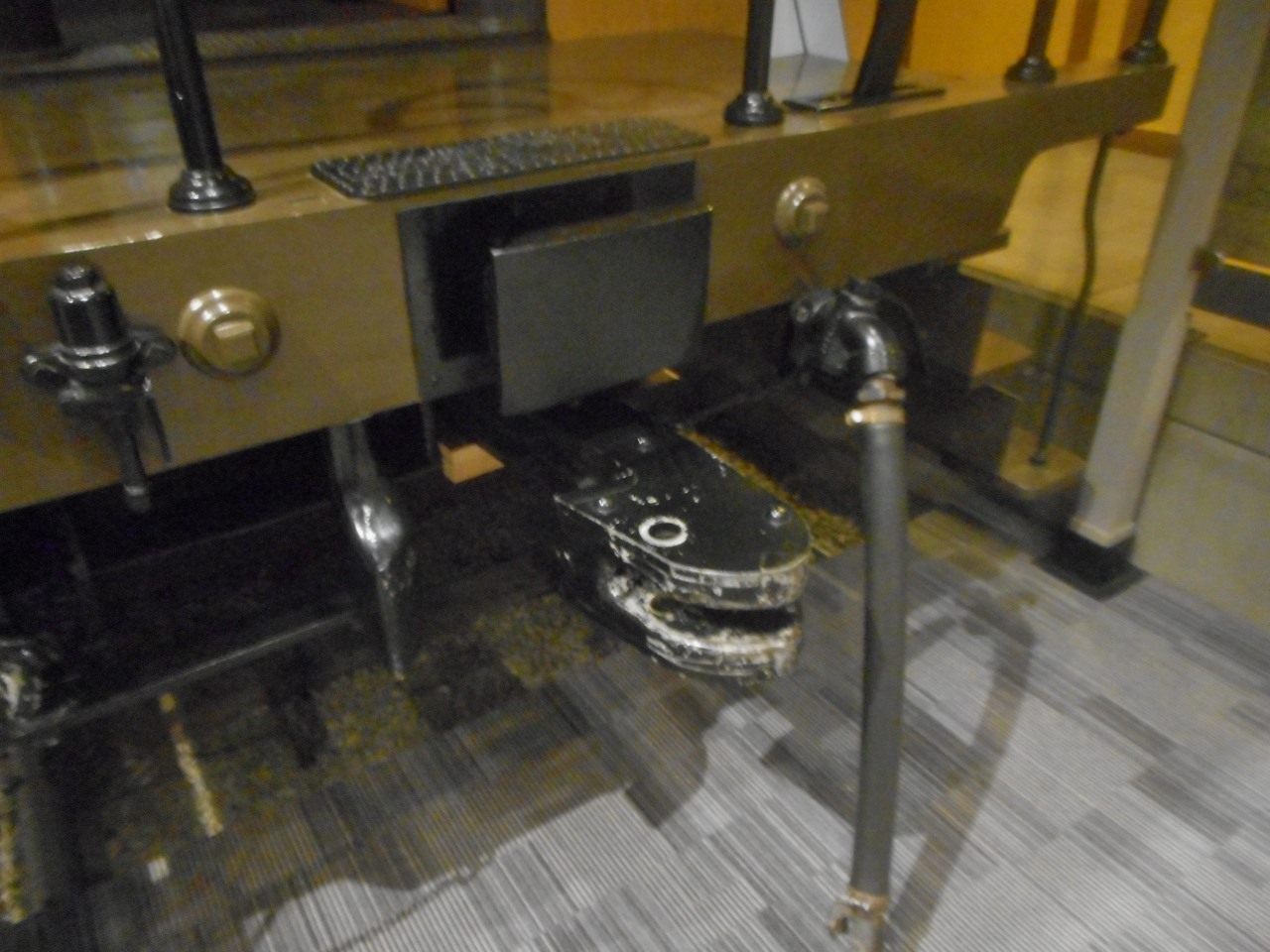
Draw gear
[edit]A draw gear (also known as a draft gear) is the assembly behind the coupling at each end of the wagon to take care of the compression and tension forces between the wagons of trains. Early draw gears were made of wood, which was gradually replaced by steel.
Janney couplers have the draft gear in a centersill to absorb the pushing and pulling forces (slack action).[66]
There is also a draw gear behind tightlock couplers, SA3 couplers, C-AKv couplers, Scharfenberg couplers, and other multi-function couplers.
In the case of buffers and chain couplers, the draw gear behind the hooks, if any, will absorb the tension, while the side buffers will absorb the compression.
Some couplers may not have a draw gear.
Model railway couplers
[edit]On model railroads couplers vary according to scale, and have evolved over many years. Early model trains were coupled using various hook-and-loop arrangements, which were frequently asymmetrical, requiring all cars to be pointing in the same direction. In the larger scales, working scale or near-scale models of Janney couplers were quite common, but proved impractical in HO and smaller scales.
For many years, the "X2F" or "Horn-Hook" coupler was quite common in HO scale, as it could be produced as a single piece of moulded plastic. Similarly, for many years, a "lift-hook" coupler known as the Rapido and developed by Arnold, a German manufacturer of N-scale model trains, was commonly used in that scale.
The chief competitor of both these couplers, more popular among serious modellers, was the Magne-Matic, a magnetically released knuckle coupler developed by Keith and Dale Edwards, and manufactured by Kadee, a company they started. While they closely resemble miniature Janney couplers, they are somewhat different mechanically, with the knuckle pivoting from the center of the coupler head, rather than from the side. A steel pin, designed to resemble an air brake hose, allows the couplers to be released magnetically; the design of the coupler head prevents this from happening unless the train is stopped or reversed with a mated pair of couplers directly over an uncoupling magnet. An earlier, mechanically tripped version of the design had a straight pin extending down from the knuckle itself, which engaged a diamond-shaped mechanical "ramp" between the rails, which had to be raised above rail height when uncoupling was desired.
Once the Kadee patents ran out, a number of other manufacturers began to manufacture similar (and compatible) magnetic knuckle couplers.
An exact-scale HO model of the AAR coupler has been designed and manufactured by Frank Sergent.[67] This design uses a tiny stainless steel ball to lock the knuckle closed. Uncoupling is achieved by holding a magnetic wand over the coupler pair to draw the balls out of the locking pockets.
In O scale, an exact-scale working miniature version of the "Alliance" coupler was manufactured from the 1980s by GAGO models in Australia. Since 2002 it has been marketed by the Waratah Model Railway Company.[68] European modellers tend to use scale hook and chain couplings.
In British 00 scale (similar to H0 scale) models the 'tension lock' coupler developed by Tri-ang is standard. This is similar in operation to the meatchopper type of coupling. Remote uncoupling is possible by using a sprung ramp between the rails. The design of the hooks is such that the couplings will not uncouple when under tension (instead depressing the ramp). When the train is pushed over the ramp, it will lift the coupling hooks as the train passes over. By halting the train over the ramp, it is split at this point. While it works well, it is often seen as ugly and obtrusive[citation needed] (although smaller designs are available, these are not always fully compatible with other models) and many[citation needed] British modellers prefer to retrofit either Kadee types or working hook and chain couplings.
A recent development is an interchangeable coupling which plugs into a standardised socket, known as NEM 362 and which can be easily unplugged as required. This allows the modeller to easily standardise on whatever coupling is desired, without individual manufacturers needing to change their coupling type.
In 7 mm scale, scale working Norwegian couplings are now being manufactured by Zamzoodled[69] in the UK.
A comparison of coupler types was published in "An introduction to Couplers".[70]
Wooden and plastic trains
[edit]Toy trains have a wide variety of incompatible couplers. for example, most wooden train companies like Brio, Thomas Wooden Railway, and Whittle Shortline use standard magnets for connecting different trains and freight cars to each other. Other forms of connection feature white plastic hook and loop couplers, mainly used by the Japanese Toy Train Company, Plarail.
Accidents
[edit]Different kinds of coupling have different accident rates.
- The Murulla rail accident of 1926 involved the breakage of a "drawhook" leading to a downhill runaway and then a collision. Drawhooks imply "buffers and chain couplers".[71]
- Round Oak rail accident – 1858 – coupling broke and the rear of train rolled back.
See also
[edit]- Buckeye Steel Castings
- Drawbar
- Gangway connection
- Gender of connectors and fasteners
- Jane's World Railways, lists the couplers used on every railway system
- Railway coupling by country
- Railway coupling conversion
- Slack action
- Three-point hitch
Notes
[edit]References
[edit]- ^ Train Couplers 101 - How do train cars stay together?, 9 April 2023, retrieved 2023-04-17
- ^ DAC Report 2020, p. 7.
- ^ Bruno Lämmli: Zug- / Stossvorrichtung. Auf: Lokifahrer, 2021.
- ^ Miller Hook
- ^ a b "Setesdals Railway". Members.ozemail.com.au. Archived from the original on 2016-03-04. Retrieved 2016-04-08.
- ^ "Lloyd MCA-PH". LAF.
- ^ a b c d e f Suid-Afrikaanse Vervoerdienste (South African Transport Services) (1983). Passassierswa- en Trokhandboek (Passenger Carriage and Truck Manual), Vol 1, Hoofstukke 1-15 (Chapters 1-15). South African Transport Services, 1983. Chapter 13.
- ^ George Hart, ed. (1978). The South African Railways - Historical Survey. Bill Hart, Sponsored by Dorbyl Ltd. pp. 9, 11–13.
- ^ a b c Holland, D. F. (1972). Steam Locomotives of the South African Railways. Vol. 2: 1910-1955 (1st ed.). Newton Abbott, England: David & Charles. pp. 51–52, 117–118. ISBN 978-0-7153-5427-8.
- ^ a b c Paxton, Leith; Bourne, David (1985). Locomotives of the South African Railways (1st ed.). Cape Town: Struik. pp. 6, 110–112, 156–157. ISBN 0869772112.
- ^ Holland, D.F. (1971). Steam Locomotives of the South African Railways. Vol. 1: 1859–1910 (1st ed.). Newton Abbott, England: David & Charles. pp. 84–87, 109–112. ISBN 978-0-7153-5382-0.
- ^ Espitalier, T.J.; Day, W.A.J. (1944). The Locomotive in South Africa - A Brief History of Railway Development. Chapter III - Natal Government Railways. South African Railways and Harbours Magazine, May 1944. pp. 337-340.
- ^ Espitalier, T.J.; Day, W.A.J. (1944). The Locomotive in South Africa - A Brief History of Railway Development. Chapter IV - The N.Z.A.S.M.. South African Railways and Harbours Magazine, October 1944. pp. 762, 764.
- ^ Espitalier, T.J.; Day, W.A.J. (1944). The Locomotive in South Africa - A Brief History of Railway Development. Chapter III - Natal Government Railways (Continued). South African Railways and Harbours Magazine, September 1944. p. 669.
- ^ South African Railways & Harbours/Suid Afrikaanse Spoorweë en Hawens (15 Aug 1941). Locomotive Diagram Book/Lokomotiefdiagramboek, 2′0″ & 3′6″ Gauge/Spoorwydte, Steam Locomotives/Stoomlokomotiewe. SAR/SAS Mechanical Department/Werktuigkundige Dept. Drawing Office/Tekenkantoor, Pretoria. pp. 6a-7a, 25.
- ^ Espitalier, T.J.; Day, W.A.J. (1944). The Locomotive in South Africa - A Brief History of Railway Development. Chapter II - The Cape Government Railways (Continued). South African Railways and Harbours Magazine, April 1944. pp. 253-257.
- ^ Dulez, Jean A. (2012). Railways of Southern Africa 150 Years (Commemorating One Hundred and Fifty Years of Railways on the Sub-Continent – Complete Motive Power Classifications and Famous Trains – 1860–2011) (1st ed.). Garden View, Johannesburg, South Africa: Vidrail Productions. p. 232. ISBN 9 780620 512282.
- ^ DAC Report 2020, p. 13.
- ^ "Internet Archive Search: creator:"Master Car-Builders' Association"". Archive.org. Retrieved 2016-04-08.
- ^ "Eli Janney - The Janney Coupler". Inventors.about.com. Archived from the original on 2008-11-06. Retrieved 2016-04-08.
- ^ a b "Ohio Brass Co. Company Profile on". Aecinfo.com. Retrieved 2016-04-08.
- ^ a b "Ohio Brass Started As Small Jobbing Foundry In 1888" (PDF). Rootsweb.ancestry.com. Retrieved 2016-04-08.
- ^ AAR Manual of Standards and Recommended Practices, Section S, Part III:Coupler and Yoke Details, Issue 06/2007
- ^ a b DAC Report 2020, p. 30–31.
- ^ a b DAC Report 2020, p. 19.
- ^ "ДЖД - Толковый словарь". Railways.id.ru. 2005-05-16. Archived from the original on 2014-04-26. Retrieved 2016-04-08.
- ^ Light Railways, October 2013, p. 23
- ^ "Sweden introduces 32.5-tonne axleloads on Iron Ore Line". Archived from the original on 2017-10-29. Retrieved 2017-10-29.
- ^ DAC Report 2020, p. 22.
- ^ "The SAB WABCO C-AK for goods wagons". Archived from the original on May 19, 2009. Retrieved October 15, 2009.
- ^ a b State of the Art on Automatic Couplers 2017, p. 18.
- ^ DAC Report 2020, p. 20.
- ^ a b DAC Report 2020, p. 5.
- ^ "The Automatic Center Coupler for European Railways". Archived from the original on July 18, 2011. Retrieved November 16, 2010.
- ^ "History of the European Automatic Centre Coupler for Goods Wagons". Archived from the original on October 30, 2007. Retrieved August 3, 2008.
- ^ a b State of the Art on Automatic Couplers 2017, p. 19.
- ^ DAC Report 2020, p. 9.
- ^ a b DAC Report 2020, p. 11.
- ^ "Faiveley Transport Group - Systems and services for the railway industry". Faiveleytransport.com. Retrieved 2016-04-08.
- ^ State of the Art on Automatic Couplers 2017, p. 26.
- ^ State of the Art on Automatic Couplers 2017, pp. 19–20.
- ^ Analysis of the basic parameters for maintaining the technical and operational compatibility of the 1520 mm and 1435 mm gauge rail systems at the Commonwealth of Independent States (CIS)/European Union (EU) border. Rolling stock. Passenger carrriages (PDF). OSJD-ERA Contact Group. 2013. Retrieved 2023-12-16.
- ^ "All purpose couplers: "Willison" type couplers". LAF. Archived from the original on 2021-05-07. Retrieved 2021-02-17.
- ^ DAC Report 2020, p. 10.
- ^ GB patent 190525511A, J.T. Jepson, "Improvements in connection with Automatic Couplings for Railway Vehicles and the like", published 1906-08-16
- ^ "ABC Couplers". Archived from the original on May 21, 2009. Retrieved October 4, 2008.[dead link]
- ^ ABC
- ^ Ramaer 2009, p. 156.
- ^ a b US patent 737673, Robert B. Stearns & Frank D. Ward, "Car-coupling", published 1903-09-01
- ^ "Coupling, Handing and UNDMs". Trainweb.org. 2002-08-24. Retrieved 2016-04-08.
- ^ "Prototype Couplers". Sumida Crossing.
- ^ OTIS Wang. "臺北捷運C381型高運量電聯車". 雪花台灣.[permanent dead link]
- ^ "Voith". Voithturbo.de. Retrieved 2016-04-08.
- ^ DAC Report 2020, pp. 26, 30–31.
- ^ "BMDV - DAC Demonstrator Pilot Project for the Demonstration, Testing and Approval of the Digital Automatic Coupling (DAC) for Rail Freight Transport (Englisch)" (PDF). bmdv.bund.de. Retrieved 2025-05-06.
- ^ "Dellner couplers modular concept - Part 1: Coupler heads". Global Railway Review. Retrieved 2025-05-06.
- ^ a b "Coupling, Handing and UNDMs". Tubeprune.
- ^ "Coupler systems for trains and metros". William Cook.
- ^ "Voith at Railtex 2013 More Sustainable Vehicle Components for Rail Transport". Voith.
- ^ "Coupling & uncoupling".
- ^ a b c Madörin, Dominik. "+GF+-Kupplung". tram-bus-basel.ch. Retrieved 2023-12-21.
- ^ a b DAC Report 2020, p. 29.
- ^ DAC Report 2020, p. 26.
- ^ "Prototype Couplers". Sumida Crossing. Retrieved 2016-04-08.
- ^ Adapter piece
- ^ How Does a Draft Gear Absorb Railcar Energy?. YouTube. 8 March 2012. Retrieved 2016-04-08.[dead YouTube link]
- ^ "Sergent Engineering Home Page". Sergentengineering.com. Archived from the original on September 30, 2002. Retrieved 2016-04-08.
- ^ "ModelOKits – Product Information and Online Store". Waratahmrc.com.au. Archived from the original on 2014-05-17. Retrieved 2016-04-08.
- ^ "Zamzoodled home page". Zamzoodled.co.uk. Archived from the original on 2016-03-28. Retrieved 2016-04-08.
- ^ Model Railways in Australia, issue 3, 2009.
- ^ "MURULLA ACCIDENT". The Sydney Morning Herald. National Library of Australia. 23 October 1926. p. 16. Retrieved 17 December 2011.
Sources
[edit]- Tymczasowe wytyczne obsługi sprzęgu samoczynnego typu UIC/OSŻD, radzieckiego – typu SA3 oraz sprzęgu mieszanego [Interim guidelines for operation of automatic coupler type UIC/OSJD, Soviet—SA3 and adapter] (in Polish). Warsaw: Ministerstwo Komunikacji. 1979.
- Development of Functional Requirements for Sustainable and Attractive European Rail Freight: D5.1 – State of the Art on Automatic Couplers (PDF) (Technical report). Shift2Rail. 3 March 2017.
- Prof. Dr. Markus Hecht, Markus; Mirko Leiste, M.Sc.; Saskia Discher, B.Sc., eds. (29 June 2020). Development of a concept for the EU-wide migration to a digital automatic coupling system (DAC) for rail freight transportation (PDF) (Technical report). Berlin: Technische Universität Berlin for the Federal Ministry of Transport and Digital Infrastructure (BMVI).
- Norfolk & Western Railway Co. v. Hiles (95-6), 516 U.S. 400 (1996) (U.S. Supreme Court decision by Justice Clarence Thomas)
- Eli Janney — The Janney Coupler Archived 2008-11-06 at the Library of Congress Web Archives (based on above case)
- Dellner Couplers AB — Automatic and Semi-Permanent Couplers
- Vancouver SkyTrain Light Rail Network, Canada (these two for Dellner data)
- JANE'S WORLD RAILWAYS
- How couplings work
- White, John H. (1985) [1978]. The American Railroad Passenger Car. Baltimore, Maryland: Johns Hopkins University Press. ISBN 978-0-8018-2743-3.
- Ramaer, Roel (2009). The Railways of Thailand (2 ed.). Bangkok, Thailand: White Lotus. ISBN 978-974-480-151-7.
Further reading
[edit]Tomlinson, G. W. (1991). "Electrical Systems via Couplers". Proceedings of the Institution of Mechanical Engineers, Part F: Journal of Rail and Rapid Transit. 205 (1): 65–78. doi:10.1243/PIME_PROC_1991_205_217_02. S2CID 111315979.
External links
[edit]- US patent 4102459, Axel Schelle & Kuno Nell, "Adaptor device for coupling railway vehicles having different types of couplers", published 1978-07-25, Adapter between Janney coupler and SA3 coupler
| International | |
|---|---|
| National | |
| Other | |
Railway coupling
View on GrokipediaTerminology and Fundamentals
Nomenclature
A coupler is a mechanism located at the ends of rail vehicles designed to connect them together, transmitting tensile and compressive forces between cars or locomotives and adjacent rolling stock. The drawbar forms the rigid extension of the coupler between its head and the vehicle body, serving to transfer pulling forces from one unit to another. Buffers act as shock-absorbing elements at the vehicle's end to mitigate impacts during compression, distinct from draft systems that handle tension. The shank refers to the section of the coupler extending from the head to its fixed attachment point on the vehicle underframe. Draft gear constitutes a suspension assembly that cushions longitudinal buff (compressive) and draft (tensile) forces acting on the coupler. Railway couplers are classified by operation into manual types, which require physical intervention for coupling and uncoupling, and automatic types, which engage without direct manual alignment but may need tools for release. Buffer configurations vary by position: top-mounted for electrical connections above the mechanical coupler, bottom-mounted for pneumatic lines below, and center-mounted for primary mechanical alignment. Compatibility is governed by standards such as those from the Association of American Railroads (AAR), which specify interchangeable designs for North American freight operations, and the International Union of Railways (UIC), which outline requirements for European interoperability.[8] Terminology for railway couplings evolved significantly from the 19th century, when British systems used "chain" or "hook and chain" to describe a flexible chain-and-hook arrangement for connecting vehicles, often paired with separate buffers. By the 1870s, American innovations shifted toward "knuckle" couplers, patented by Eli Janney in 1873 as a semi-automatic device with a pivoting jaw-like element for secure engagement.[9] This transition culminated in standardized AAR designations by the early 20th century, such as the Type E coupler adopted in 1930, which refined the knuckle design for broader use and marked the decline of link-and-pin nomenclature.[9] Key components of modern couplers include the knuckle, a pivoting element that interlocks with the adjacent coupler to form the connection; the tailpiece, an extension of the knuckle that aids in locking and anti-creep mechanisms; the pin, which secures the knuckle's pivot and yoke assembly; and buffing gear, which absorbs compressive forces at the vehicle's end to protect the underframe.[10]Draw Gear and Buffing
The draw gear in railway vehicles serves to absorb and transmit both tensile (draft) and compressive (buff) forces generated during train acceleration, deceleration, starting, and stopping, thereby protecting the underframe and coupling components from excessive stress.[11] It typically incorporates spring systems, such as friction drafts or elastomeric elements, which allow controlled movement—often up to 50-80 mm of travel—to dissipate energy and reduce oscillations between vehicles.[12] These systems function by converting kinetic energy into heat or deformation, with friction drafts using wedge-shaped blocks pressed against plates to provide damping, while elastomeric drafts rely on rubber or polymer compression for progressive resistance.[13] Buffing gear, closely integrated with the draw gear in many designs, specifically handles compressive impacts, such as those from shunting operations or minor collisions, using buffers fitted with rubber or steel spring elements to cushion forces and prevent structural damage.[13] In European systems, these buffers are standardized under EN 15551 for strokes of 105-150 mm and energy capacities of at least 30 kJ, ensuring compatibility across vehicles with screw couplings.[13] The gear mitigates peak compressive forces, which can reach up to 1,000 kN during impacts, by dissipating energy through progressive stiffness curves that increase with displacement, thus limiting acceleration to safe levels for passengers and cargo.[12] Alignment mechanisms within the draw and buffing gear, including centering devices and guide elements, ensure proper engagement of coupling components by automatically returning the drawbar shank to a central position after lateral shifts caused by track curvature or misalignment.[11] These devices, often comprising springs or pins that act against the yoke or carrier, limit excessive lateral swing to ensure proper alignment and force transmission, reducing derailment risks.[14] Overall, the combined draw and buffing systems maintain train integrity by balancing preload (typically 10-50 kN) with dynamic absorption, adhering to standards like EN 15566 for draw gear performance under varying temperatures and loads.[13]Pre-Automatic Coupling Systems
Buffers and Chain
The buffer-and-chain coupling system originated in Britain during the 1830s on early railways such as the Liverpool and Manchester Railway, where it evolved from simpler tramway practices to accommodate the growing demands of steam-powered operations.[15] This design typically incorporates two buffers positioned at each end of the rail vehicle—one on each side of the coupler centerline—to handle compressive forces during impacts, paired with short chain links that connect adjacent vehicles via hooks mounted on the underframe.[15] The buffers, often spring-loaded with rubber or friction elements, compress to absorb shocks, while the chains provide the tensile connection, allowing for some slack in the coupling.[16] In operation, the system requires manual attachment and detachment, with shunters positioning themselves between vehicles to hook the chain links and adjust tension, often using a turnbuckle screw in later variants to pre-compress the buffers slightly and reduce slack.[15] The chains transmit pulling forces during acceleration or braking, while the buffers manage compression forces through elastic deformation, integrating with draw gear components at the vehicle's rear to further dissipate longitudinal shocks.[17] This manual process, though straightforward, demands precise alignment of vehicles, typically achieved by shunting maneuvers that bring the buffers into contact before securing the chain.[18] The system's primary advantages lie in its simplicity and low cost, making it suitable for the lighter freight and passenger trains of the 19th and early 20th centuries, with minimal components required for manufacturing and maintenance.[15] However, its limitations include high labor intensity for coupling operations and inherent safety risks during shunting, where workers face hazards such as being crushed between compressing buffers or caught in moving chains, leading to frequent injuries like pinched limbs.[18] It became the dominant standard across the United Kingdom, France, and much of continental Europe, influencing designs until the International Union of Railways (UIC) formalized compatible standards in the 1960s, after which many networks began transitioning away from loose-chain variants toward more standardized screw couplings or, later, automatic systems to address inefficiencies.[15][17]Link and Pin
The link-and-pin coupler, an early coupling system prevalent in American railroading, featured a wrought-iron link shaped as an elongated loop that was inserted into eyes or sockets on the drawbars of adjacent cars and secured by a vertical iron pin dropped through aligned holes.[16][19] This design originated in the United States during the 1830s, shortly after the advent of railroads, and became the standard for connecting freight and passenger cars due to its simplicity and low manufacturing cost using readily available iron.[19][16] Operation of the link-and-pin coupler was entirely manual and hazardous, requiring a brakeman or switchman to position themselves between the slowly approaching cars to guide the link into the receiving eye and insert the pin, often while the train was in motion or under minimal control.[19][16] Uncoupling followed a similar process in reverse, with the worker removing the pin by hand. This proximity to moving cars resulted in severe injury risks, including crushed limbs and fatalities from the jerky motion and slack in the connection; by 1888, coupling operations alone caused approximately 6,700 injuries and 300 deaths annually across U.S. railroads, contributing to broader rail worker casualty rates exceeding 8,000 incidents per year in the late 19th century.[19][20] Key limitations of the link-and-pin system included significant operational slack that produced jarring shocks during starts and stops, as well as challenges with misalignment, particularly on curved tracks where drawbars could swing outward, complicating manual alignment and increasing failure risks.[16] Variable link lengths across different manufacturers further exacerbated these issues, leading to inconsistent compatibility between cars from various railroads and frequent uncoupling or derailments.[19] These drawbacks made the coupler inefficient for longer trains and higher speeds, prompting gradual experimentation with alternatives by the 1870s.[21] Historically, the link-and-pin coupler dominated U.S. rail lines from the 1830s through the late 19th century, equipping the majority of freight cars during the expansion of networks like the Transcontinental Railroad in the 1860s.[16][19] Its phase-out accelerated in the 1880s as railroads adopted semi-automatic designs, culminating in the federal Railway Safety Appliance Act of 1893, which mandated the replacement of manual couplers like the link-and-pin with automatic systems on all interstate lines by January 1, 1900, to curb worker injuries and improve safety.[21][19]Balance Lever Coupling
Lever-assisted link-and-pin couplers emerged as enhancements to the basic link-and-pin system in the United States, incorporating a dedicated lever to facilitate the raising and lowering of the coupling link from the side of the track, thereby minimizing the need for workers to position themselves between rail cars during engagement. This design addressed key safety hazards of the era by reducing exposure to the dangerous space between approaching vehicles. Examples were patented in the United States during the 1860s and 1870s, building on the basic link-and-pin mechanics while introducing mechanical assistance for link manipulation.[22] In operation, the lever, often connected via a rod or pivot system, engages the link to pivot it upward into alignment for insertion into the opposing drawbar, with the pin then dropped to secure the connection. This side-accessible mechanism permitted the link to be held in an elevated position during coupling, easing alignment on slightly uneven tracks and allowing engagement without direct intervention between cars. The process remained manual but shifted much of the physical risk away from the coupling zone.[22] Adoption was confined primarily to select railroads in the United States and Canada in the mid-19th century, where it served as a transitional safety measure on freight and mixed trains. However, its relative complexity and higher manufacturing cost limited broader implementation, as most lines retained the simpler, inexpensive link-and-pin coupler until regulatory pressures and technological advances favored fully automatic alternatives.[16] Key drawbacks included its continued reliance on manual intervention, which could still expose workers to injury if the lever failed to hold the link securely, and vulnerability to mechanical issues in harsh operating conditions, such as derailments or heavy jolts that could dislodge components. These limitations, combined with inconsistent performance on longer or faster trains, prevented lever-assisted designs from achieving widespread or long-term use.[16]Albert Coupler
The Albert coupler is a semi-automatic railway coupling system developed in Germany during the 1920s by Karl Albert, director of the Krefeld Tramway. The design featured a key-and-slot mechanism with two pins that engaged upon impact, allowing hookup between vehicles while requiring manual intervention for release. This approach aimed to improve safety over manual chain couplings in urban rail operations, particularly for trams, by reducing the need for workers to go between vehicles. Tested on German tramways, the coupler addressed hazards in close-quarters shunting but faced operational challenges, including jamming on tight curves due to the slot alignment and higher manufacturing costs compared to traditional methods. These limitations restricted its adoption to niche urban and light rail applications, with little influence on mainline railways. Despite limited use, the Albert coupler represents an early 20th-century European effort toward safer, semi-automatic coupling technologies in the pre-full-automatic era.[16]Miller Hook and Platform
The Miller Hook and Platform was a semi-automatic coupling system developed in the United States during the 1860s as an improvement over the hazardous link-and-pin method, which required workers to position themselves between cars. Invented by Ezra Miller, a civil engineer and politician, the system received its initial patent (U.S. Patent No. 38,057) on March 31, 1863, for the basic coupler and draft gear design featuring double-beveled hooks with long shanks that projected beyond the car platforms. Subsequent patents, including U.S. Patent No. 56,594 in 1866, refined the trussed platform and compression bumper elements, incorporating an elevated buffer-beam supported by longitudinal beams, cross-timbers, and truss rods to align with the car bed and absorb shocks. The hook itself consisted of a cast-iron body with wrought-metal plates and chilled surfaces for durability, paired with a link that allowed interlocking without manual insertion between cars. In operation, the Miller Hook engaged automatically as cars approached, with the hooks' oblique surfaces guiding them into position while lateral springs pressed the hooks together, and buffers compressed about one inch to eliminate slack and maintain constant tension. Uncoupling occurred from the side via a lever and chain connected to the brakeman's platform, which raised the hook for release, eliminating the need to access the space between cars—a key safety feature especially on elevated urban lines where platforms provided stable footing. This design was particularly suited for passenger cars, as the spring-loaded buffers reduced jerks and enhanced ride comfort during starts and stops. Adoption was limited primarily to urban passenger railroads in the U.S., becoming a standard by 1875 on lines like those in Chicago, where the system's compatibility with close-clearance elevated tracks proved advantageous. However, its high manufacturing cost restricted use to passenger service, while freight trains retained cheaper link-and-pin couplers, and overall incompatibility with emerging knuckle designs like the Janney coupler (patented 1873) confined it to niche applications for several decades. The system faced durability challenges, including rapid wear on the hooks due to constant friction and lateral spring pressure, as well as fragility in the trussed platforms from repeated compression and track irregularities, which contributed to its eventual replacement by more robust automatic couplers.Radial and Link-Based Couplers
Johnston Coupler
The Johnston coupler is an automatic knuckle-type freight car coupler developed in the late 19th century by the Johnston Car Coupler Company of Philadelphia, conforming to Master Car Builders (M.C.B.) standards and the U.S. Safety Appliance Act of 1893 (effective January 1, 1898).[23] It features a design similar to the Janney coupler, with a locking knuckle mechanism for engagement upon impact, parts moving in a horizontal plane within a vertical-plane coupler body.[24] Operation of the Johnston coupler is automatic, coupling by impact without workers needing to go between cars, and uncoupling is performed using side levers and rods for safety. Developed to meet Master Car Builders standards and the Safety Appliance Act of 1893, it ensured compatibility across U.S. railroads, with standardized heights (34.5 inches for freight cars).[24] Its primary advantages include automatic coupling for improved safety and efficiency in freight operations, reducing manual intervention risks. It was used on various railroads, including locomotives and tenders from Baldwin Locomotive Works, but largely superseded by standardized Association of American Railroads (AAR) couplers in the 20th century.[23]Bell-and-Hook Coupler
The Bell-and-Hook Coupler features a bell-shaped housing integrated with a pivoting hook mechanism, designed for manual engagement in radial configurations. This system originated in 19th-century Britain through innovations by Robert Hudson and Co., a Leeds-based firm founded in 1865 specializing in mining and industrial railway equipment, including colliery tubs and couplings tailored for heavy-duty, low-speed operations.[25][26] In operation, the pivoting hook on one vehicle engages the bell-shaped mouth of the opposing coupler radially, allowing alignment within a limited swing angle to accommodate track curves; manual pinning secures the connection, often guided by a bell-mouthed buffer slot that facilitates entry of links or hooks even if slightly misaligned. The design supports a breaking force of 70 tons, suitable for pairings with 25-ton locomotives common in colliery settings.[26] Prevalent on UK industrial railways, particularly collieries, the coupler remained in use through the 20th century and into the late industrial era, though now largely confined to heritage and preservation lines due to the decline of coal mining infrastructure.[26] Compared to traditional chain systems, the Bell-and-Hook Coupler enhances safety during shunting by enabling hands-free engagement in some variants, permitting operators to stand clear and reducing exposure to pinch points and moving parts. However, it requires manual intervention for uncoupling, which can pose risks if not performed correctly.[26]Norwegian Coupler
The Norwegian coupler, also known as the chopper or meat chopper coupler, is a manual radial link system developed in Norway during the 1860s for narrow gauge railways. It was first introduced on the third Norwegian narrow gauge line around 1866, following the initial use of link-and-pin couplings on the first two lines.[27] The design integrates a central buffer with side chains for securing the connection and a blade-like arm that drops into a slot on the opposing buffer's headstock, providing both buffing and drawing functions in a compact form suitable for 1067 mm (3 ft 6 in) gauge tracks.[28] This radial configuration allows lateral movement to accommodate track curves on mixed-traffic lines, enhancing operational flexibility without requiring uncoupling for tight turns. Operation of the Norwegian coupler is entirely manual, with railway crew positioning the blade and fastening the chains to engage and disengage vehicles, a process that demanded careful alignment but minimized slack compared to earlier link systems. Its buffer integration made it compatible with prevailing European standards for compression forces, facilitating interoperability with imported rolling stock on Norway's developing network. The coupler's simple, robust construction proved effective for freight and passenger services on uneven terrain, though it lacked automatic engagement features common in later designs. The Norwegian coupler saw widespread adoption as the standard on the Norwegian State Railways (NSB) narrow gauge network, which expanded to a peak of 1055 km by 1896 and included key lines like the Røros and Setesdal branches.[29] It remained in service across these lines until systematic conversions to standard gauge (1435 mm) began in the early 20th century, with major regaugings such as the Bergen–Voss line in 1904 and the Røros line during World War II; by 1949, all NSB-owned narrow gauge lines had been converted or closed, except the Setesdal line, which operated until 1962.[29] Although influenced by earlier European link-based systems like the bell-and-hook coupler, the Norwegian variant emphasized radial freedom and buffer compatibility for local conditions. Post-conversion, surviving examples persisted on preserved tourist segments, such as an 8 km stretch of the Setesdal line.[29]Automatic Couplers
Janney Coupler and Variants
The Janney coupler, also known as the knuckle coupler, represents a pivotal advancement in railway coupling technology, introducing semi-automatic engagement to enhance safety and efficiency on North American rail networks. Invented by Eli H. Janney, a Confederate Army veteran, the original design was patented in 1873 as U.S. Patent No. 138,405, featuring a knuckle mechanism that automatically interlocks upon impact between rail cars, thereby eliminating the hazardous manual insertion required by its predecessor, the link-and-pin system. Subsequent refinements were patented in 1879 (U.S. Patent No. 216,470) and 1882 (U.S. Patent No. 249,946), incorporating a drawhead and revolving hook to improve durability and alignment.[19] This knuckle-style coupler mimics a human hand, with pivoting jaws that close securely, allowing cars to couple without workers positioning themselves between them—a practice that had caused numerous injuries and fatalities prior to its adoption.[19] In operation, the Janney coupler engages automatically when two open knuckles collide during shunting or train assembly; the impact causes the knuckles to pivot and enclose the opposing coupler, after which a gravity-actuated locking pin drops into place to secure the connection against tensile and compressive forces.[30] Uncoupling is performed semi-manually from the side of the car using an operating lever that lifts the lock pin and rotates the knuckle open, enabling separation without direct intervention between cars.[30] This design inherently provides some lateral play to accommodate track curves and vertical variations in car heights, while the uncoupled knuckles remain in an open position ready for the next engagement. Early implementations focused on freight cars, where the coupler's robustness allowed for reliable performance under heavy loads, significantly reducing the labor-intensive and dangerous aspects of train formation.[19] Standardization efforts began in the late 19th century to ensure interoperability across railroads. In 1887, the Master Car Builders Association (MCB) selected the Janney design as the basis for a uniform coupler after evaluating over 40 competing inventions, designating it the MCB coupler with the No. 10 contour for consistent knuckle profiles.[21] By the 1910s, the American Railway Association (ARA), the MCB's successor, refined this into the Type D coupler in 1916, emphasizing interchangeable parts and improved gathering range for easier alignment.[31] The American Railway Association (ARA) adopted the Type E coupler in 1930, which the Association of American Railroads (AAR; formed in 1934) further advanced; the Type E increased knuckle depth from 9 to 11 inches for enhanced strength and a rated buffing capacity exceeding 3,559 kN (800,000 lbf) to handle heavier freight trains.[32][33] These standards mandated compatibility, facilitating seamless car interchange and contributing to the coupler's widespread adoption. Key variants emerged through ongoing modifications to address specific operational needs. In the 1920s, inventor A.J. Bazeley introduced a rotary lock mechanism via U.S. Patent No. 1,518,299 (1925), which allowed the lock to rotate upward for uncoupling, reducing wear and improving reliability on high-impact freight lines.[34] Post-1873 improvements included tighter knuckle contours, such as the AAR No. 5 profile developed in the mid-20th century, enabling reliable coupling on sharper curves up to a 1:18 radius ratio while maintaining a gathering range of approximately 18 inches laterally.[31] For European adaptation, the Henricot coupler, patented in the early 20th century (e.g., related designs in U.S. Patent No. 1,282,177, 1918), modified the Janney knuckle for buffer-equipped continental rolling stock, incorporating adjustable heights and electrical connections for compatibility with mixed traffic. The Janney coupler and its variants dominate freight and passenger operations in the United States, Canada, and Mexico, where AAR standards ensure over 1.5 million freight cars can interchange freely across borders.[31] Recent updates by the American Public Transportation Association (APTA) have focused on high-speed applications, with standards like PR-CS-RP-019-12 (2012) recommending pushback features in Type H tightlock variants to mitigate crash forces in commuter and intercity services exceeding 125 mph.[35] These enhancements, including reinforced knuckles for dynamic loads, support safer operations on modern networks while preserving the core automatic engagement principle established over 150 years ago.[36]Willison SA3 Coupler and Derivatives
The Willison SA3 coupler is an automatic railway coupling system characterized by a bottom-mounted rotary hook mechanism that enables secure connections between freight and passenger vehicles. Originally developed as the Willison coupler in the early 20th century and patented in the United States in 1916, it addressed limitations in earlier link-and-pin systems by providing semi-automatic engagement. The design was refined and adopted in the Soviet Union during the 1930s as a semi-automatic variant, evolving into the fully automatic SA3 standard by 1957 for widespread use on standard-gauge lines. This coupler features a robust head with a pivoting hook that rotates to lock upon impact, supported by a center section incorporating deformation tubes for energy absorption during shunting and operation.[15][17] In operation, the SA3 coupler achieves automatic engagement when two vehicles are pushed together at speeds up to 10 km/h, with the rotary hook on one coupler intermeshing and locking with the receiving shank on the opposing unit without manual intervention from beneath the train. Uncoupling is typically performed using a ground-level screw mechanism to rotate the hook open, though advanced variants incorporate pneumatic cylinders for remote activation from the locomotive cab, enhancing safety and efficiency. The system is engineered to withstand tensile forces up to 1,000 kN and compressive forces similarly, making it suitable for heavy freight trains with total masses exceeding 6,000 tonnes, while vertical and horizontal misalignment tolerances of approximately 140 mm and 175 mm, respectively, accommodate track irregularities. Its modular construction allows integration with draft gears and optional electrical or pneumatic connections for brake and control lines. As of 2025, SA3-based systems are being integrated with Digital Automatic Coupling (DAC) technology to enable automatic brake and electrical connections, supporting EU-Ukraine interoperability under TSI standards.[37][38][39][40] Derivatives of the SA3 coupler include several inter-compatible adaptations designed for hybrid operations across differing regional standards. The Unicoupler and Intermat (also known as AK69) systems incorporate adapters that enable SA3 heads to mate with Janney/AAR couplers, facilitating cross-border freight without full vehicle modifications; these were developed in the 1960s and 1970s primarily in France for European compatibility. The C-AKv, a Polish variant produced by Faiveley Transport (now Wabtec), extends the SA3 outline with hybrid buffers for coupling to traditional European screw-link systems while maintaining direct SA3 interoperability and a 1,000 kN tractive capacity. Similarly, the Z-AK coupler, developed in Czechoslovakia (now Czech Republic), refines the rotary hook for enhanced durability in industrial shunting. The Unilink coupler, offered by manufacturers like LAF, provides a modular framework compatible with SA3 profiles and UIC screw couplers, featuring optional fusible links for overload protection and pneumatic uncoupling.[38][41][42] The SA3 coupler remains the standard for freight operations in countries of the former Soviet bloc, including Russia, Ukraine, and the Baltic states, where it supports efficient train formation on extensive networks. Its adoption extends to parts of Asia, with ongoing use in 2025 for heavy-haul freight in regions influenced by Soviet-era infrastructure, such as connections to China and Iran via Central Asian corridors, ensuring compatibility in international block trains. Modern upgrades, including digital automatic coupling (DAC) variants, continue to build on the SA3 base to meet evolving EU and Eurasian standards for interoperability and safety.[40][15]Stearns and Ward Coupler
The Stearns and Ward coupler is an early automatic railway coupling system patented on September 1, 1903, by inventors Robert B. Stearns and Frank D. Ward of Chicago, Illinois. Developed specifically for elevated railway applications in the United States, it addressed the need for a secure, semi-automatic connection between passenger cars while improving operator safety over traditional link-and-pin systems. The design centers on a draw-head with an open throatway extending vertically from top to bottom, flanked by buffer faces to absorb impacts, and a semicylindrical pocket containing a rotative coupling-pin. This pin, spring-loaded for self-restoration, engages with a hook-bar featuring a hook-head on an H-shaped draw-bar, allowing cars to couple without manual insertion of pins or links.[43] In operation, the hook-heads of adjacent couplers align and enter the throatway during shunting, with the hook-head's notch rotating the coupling-pin to permit entry before the spring returns the pin to lock the connection securely. The mechanism prevents accidental uncoupling under normal running conditions but allows vertical separation of cars in the event of derailment, reducing the risk of telescoping or horizontal binding. Uncoupling is performed manually from the side of the car using an operating arm or rod connected to the pin, avoiding the need for workers to position themselves between cars—a common hazard with earlier designs. Paired with electric couplers for trainline control in electrified systems, the Stearns and Ward coupler facilitated reliable mechanical and electrical connections on urban passenger routes.[43][44] The coupler saw limited use on the Northwestern Elevated Railroad in Chicago, notably on the 4000-series steel cars built starting in 1914, where it served as a transitional knuckle-style design compatible with both matching knuckle couplers on new equipment and older link-and-pin types on wooden cars. This dual-compatibility was intended for mixed operations during fleet modernization but proved unsatisfactory due to mechanical complexities and reduced efficiency compared to standardized systems. By the 1940s, it was largely superseded by more advanced couplers like the Ohio Brass Form 5 on PCC cars (5000- and 6000-series), which offered better integration with pneumatic and electrical systems for automatic operations. Adapter devices were eventually developed to bridge the Stearns and Ward with newer types for emergency movements, underscoring its short-lived role in Chicago's rapid transit evolution.[44]Automatic Buffing Contact Coupler
The Automatic Buffing Contact Coupler, commonly abbreviated as the ABC coupler, represents an early 20th-century innovation in railway coupling technology, emphasizing automatic alignment and direct contact for compressive (buffing) forces between vehicles. Developed by British inventor J. T. Jepson and patented under British Patent No. 25,511 in December 1905 (accepted August 1906), it was commercialized by the Automatic Buffing Contact Coupler and Engineering Company Ltd., established on March 3, 1904, in Wolverhampton, England. The system was particularly suited for light railways, where its design facilitated quick, hands-free connection without the need for complex drawbars, though vehicles required separate buffers to manage tensile (draft) loads.[45] The core design featured a pair of overlapping shackles that interlocked via a hook upon impact, enabling automatic coupling even on curved tracks or with vertical misalignment. Standard models accommodated height differences of up to 4 inches on standard-gauge lines and 2.5–3 inches on narrow-gauge systems, with a rated breaking strain of 50 tons for smaller variants and 65–70 tons for standard ones. An enhanced iteration introduced in 1912 incorporated rotating disc hooks paired with spring-loaded locking bars, reducing wear and improving durability while maintaining a minimal number of moving parts. Uncoupling was performed manually by lifting the shackles or actuating a chain or handle, ensuring operational simplicity. This configuration prioritized buffing contact, transmitting compressive forces directly through the aligned shackles, while draft forces were handled indirectly via adjacent vehicles or supplementary buffering, limiting its application to shorter train consists typically under light loads.[45] In practice, the ABC coupler excelled in environments demanding frequent shunting and rapid assembly, such as narrow-gauge light railways in the United Kingdom and British colonial networks. Notable deployments included the Bauchi Light Railway in Nigeria starting in 1911, the Kalka–Shimla Railway in India, and systems in Ceylon (now Sri Lanka), Honduras, Australia, Kenya, and Uganda, where its automatic alignment contributed to smoother riding by minimizing jerking during starts and stops. The design's robustness and low maintenance needs made it advantageous for resource-constrained operations, though its reliance on compressive contact alone proved inadequate for longer, heavier trains prone to high draft stresses, restricting scalability. Non-automatic variants were later offered from 1919 to address specific user preferences.[45] Although the original ABC system became obsolete with the company's cessation of trading in 1961 and liquidation on June 7, 1962—amid financial challenges from patent sales and post-war market shifts—its core principles of automatic buffing alignment persist in contemporary urban metro and light rail couplers. The intellectual property was acquired by F. H. Lloyd Holdings in 1962, later passing to Triplex, and sold to Les Appareils Ferroviaires (LAF) in January 1997; LAF continues to produce compatible coupler variants for modern applications, including high-speed links like the Channel Tunnel.[46]Multi-Function and Combined Couplers
Westinghouse H2C
The Westinghouse H2C coupler is a tight-lock variant of the Janney knuckle design, developed by the Westinghouse Air Brake Company in the United States during the 1920s for integrating mechanical coupling with pneumatic air brake connections on passenger cars.[19] Its predecessor, the H2A model, was first deployed on Brooklyn-Manhattan Transit (BMT) Standard subway cars built between 1915 and 1921, marking an early adoption in urban rail systems.[47] The H2C itself became a standard feature on subsequent New York City Subway cars, such as the R1 through R9 classes, and remains in use on models like the R32, R42, R62, R62A, R68, and R68A.[48] In design, the H2C builds on the interlocking knuckle mechanism of the Janney coupler to form a secure, low-slack connection, with built-in provisions for aligning and automatically connecting air brake hoses upon engagement.[19] These hose connections, typically using gladhand fittings, link the pneumatic brake lines between cars, enabling continuous air pressure distribution for the Westinghouse automatic air brake system without separate manual attachments.[49] Primarily applied to passenger and subway cars, the coupler's compact form facilitates tight formations in high-density operations, such as those in the New York City Subway.[48] Operation involves the cars being pushed together, where the knuckle locks automatically, and the protruding hose ends mate to seal the air brake circuit, supporting rapid train assembly and brake functionality.[19] This integration aligns with the AAR's standardization of the Type H tight-lock coupler in the 1930s, which emphasized reduced slack and enhanced safety for passenger service by minimizing derailment risks from loose connections.[19] Key advantages include the elimination of manual brake hose handling, which streamlines coupling processes and reduces crew exposure to hazards during train makeup.[48] The design also promotes efficient air flow through the connected lines, improving brake response times compared to traditional link-and-pin or separate hose systems.[49] However, limitations arise from hose wear, particularly abrasion and kinking due to repeated engagements and environmental exposure, necessitating regular inspections and replacements per AAR guidelines to maintain system integrity.[49]WABCO N-Type
The WABCO N-Type coupler is a semi-automatic multi-function coupling system designed for passenger and transit rail applications, integrating mechanical, pneumatic, and electrical connections to facilitate efficient train formation. Its design features a closed-head typology with engaging teeth for rigid coupling that minimizes play between vehicles, along with a simple latching mechanism using two pins to reduce the number of moving parts and enhance reliability. Developed by the Ohio Brass Company in the mid-20th century and later incorporated into the WABCO (now Wabtec) portfolio, the coupler builds on pneumatic principles similar to the Westinghouse H2C while adding provisions for electrical signals via external holders and integrated pneumatic lines for brake control within the head frame.[17] In operation, the N-Type coupler enables automatic mechanical engagement through shunting impact, with uncoupling achieved by simultaneous release of the latches, supporting seamless connections for multiple units in electric rail systems. While primarily deployed in North American passenger and mass transit networks, such as subway and commuter EMUs, it has seen limited adoption in European contexts for transitional applications, including adapters for compatibility with UIC-standard draw hooks. The coupler's multi-function capabilities include plugs for power and signal transfer, though limited to lower voltages compared to high-speed systems, and pneumatic interfaces for brake hoses without requiring manual intervention.[17][50] Variants of the N-Type include the N-2 for standard transit use with lightweight radial draft gear for close coupling, and the N-3 tightlock version optimized for higher-speed operations with enhanced stability, primarily used in US systems like San Francisco's BART.Tomlinson Coupler
The Tomlinson coupler is a multi-function variant of the Association of American Railroads (AAR) Type H tightlock knuckle coupler, designed primarily for North American passenger rail applications with compatibility for transitional freight services. It integrates mechanical coupling with provisions for electrical and pneumatic connections, including side-mounted plugs for trainline functions such as lighting, braking, and control signals. Developed by the Tomlinson Coupler Company in the early 20th century and refined through AAR standardization in 1947, this design builds on the Janney knuckle principle by incorporating interlocking wings and machined mating surfaces to minimize slack, typically limited to 1/2 inch (1.27 cm) in free operation.[51][52][53] In operation, the Tomlinson coupler engages automatically via its knuckle mechanism when cars are pushed together within a gathering range of approximately 1 inch laterally and vertically, with the lockset confirmed by a tell-tale slot indicator. Uncoupling is achieved manually by raising the operating handle to open the knuckle or via remote mechanisms on some installations, while electrical and pneumatic interfaces connect via gladhands and jumper cables on the sides, allowing mixed consists of passenger cars and compatible freight equipment without full recoupling of utilities. This setup supports seamless integration in intercity trains, where the close coupling reduces buff and draft forces for smoother performance over curves and grades.[52][19] Key advantages include enhanced passenger safety through anti-telescoping features that prevent car override in derailments, as well as simplified operations for trailer-on-flatcar (TOFC) services by enabling quick attachment of flatcars or autoracks to passenger consists via transitional adapters. The reduced slack—compared to standard AAR Type E freight couplers—improves ride quality and minimizes wear on draft gear, contributing to longer equipment life in high-speed intercity runs.[53][19] The Tomlinson coupler served as the standard for U.S. intercity passenger equipment from the mid-20th century through the 2000s, including widespread adoption by Amtrak for its fleet of Superliner and Amfleet cars starting in the 1970s to ensure compatibility across inherited rolling stock. Recent upgrades have incorporated LED-compatible electrical interfaces to support energy-efficient lighting systems in modernized consists, extending its relevance in contemporary operations.[52]Scharfenberg Coupler
The Scharfenberg coupler, commonly abbreviated as Schaku, is a lightweight automatic coupling system primarily designed for light rail and metro vehicles. Invented in Germany by Karl Scharfenberg and patented in 1903 as a central buffer coupler with a hoop and rotatable draw hook, it was developed between 1904 and 1907 and first introduced in 1925 on the Berlin and Hamburg suburban railways.[54][38] The design adheres to the rotary interlocking principle, featuring a cone-and-cup profile where a rotating metal disc with a hoop engages a notch for secure locking, while integrated electrical contacts enable simultaneous connection of power, control, and data lines, often compliant with UIC 552 standards for train line power supply.[55][56] This multi-function capability automates mechanical, pneumatic, and electrical couplings in a compact form suitable for urban transit. Gangway covers are incorporated to protect connections and facilitate passenger passage between coupled vehicles.[55] Operation involves low-impact engagement, where vehicles approach at speeds of 0.5 to 1.2 km/h, allowing the cone to center in the opposing cup and the hoop to rotate into the notch for interlocking with minimal slack (maximum 0.8 mm per EN 16019:2014).[55] Uncoupling is achieved manually via a lever or Bowden cable mechanism on one coupler head, which disengages the rotary lock without requiring tension relief, though it cannot be performed under load. The system's large gathering range—up to ±140 mm vertically and ±275 mm horizontally—ensures reliable alignment even in curved tracks or uneven conditions typical of metro operations.[55] This design emphasizes safety and efficiency, reducing manual intervention and exposure to moving parts. Adoption of the Scharfenberg coupler is widespread in European urban rail networks, including S-Bahn systems in Germany and Switzerland, where over 3,000 Type 10 variants operate on regional and long-distance routes as of 2019.[37] In Asia, it has been implemented in metro systems such as Manila's MRT Line 3 since 1999, supporting efficient trainset formation in high-density urban environments. Its key advantages include a compact, lightweight construction ideal for low-floor vehicles, enabling tighter train configurations, improved aerodynamics, and enhanced automation potential without compromising strength (up to 1,500 kN compression and 1,000 kN tension).[37][55] Recent variants, particularly under the European Digital Automatic Coupling (DAC) program, incorporate advanced features like USB data interfaces for real-time monitoring; as of late 2025, DAC pilots are operational in Europe, with the first commercial DAC-equipped train entering service in Germany and further testing planned for 2026.[55][7][57]Dellner Coupler
The Dellner Coupler family represents a modular series of automatic couplers designed for passenger rail applications, particularly in metros, light rail, and high-speed trains, emphasizing safety and efficiency in challenging operational environments. Developed by the Swedish firm Dellner Couplers AB, these couplers integrate mechanical, pneumatic, and electrical functions to enable seamless vehicle connections while incorporating advanced energy management systems.[58][59] The design of Dellner Couplers originated in Sweden during the 1980s, with the company pioneering the integration of gas-hydraulic dampers into automatic couplers in 1984 to enhance energy absorption capabilities. These hydraulic components, typically located in the center section, provide buff and draft strengths up to 1500 kN and 1000 kN, respectively, allowing the system to mitigate impacts during coupling and collisions. The modular architecture supports various head types, including rotary designs influenced by Scharfenberg principles, and includes features like pivot anchors that shear off in crashes to prevent derailment. Anti-climb mechanisms are embedded within the overall crash energy management (CEM) structure, promoting vehicle stability during accidents.[59][60][61] In operation, Dellner Couplers facilitate remote-controlled uncoupling, ideal for metro shunting and automated train assembly, using pneumatic or electrical mechanisms to release connections without manual intervention. They integrate power and signal transmission through bottom- or top-mounted electrical couplers, such as the D-REX Ethernet system supporting 100 Mbit speeds, alongside pneumatic lines for brake and main air supply, ensuring comprehensive train control across coupled units. Energy absorption via the gas-hydraulic dampers handles up to 1.6 MJ of kinetic energy, safeguarding passengers and infrastructure in daily operations.[61][62][60] Key variants include Type 10 for regional and intercity trains, Type 12 for high-speed and metro applications, and Type 330 optimized for light rail and trams. The Type 330, for instance, has been deployed on Stockholm Metro's C30 trains since 2015, providing reliable connections for urban service. In the UK, the Type 12 LRV variant equips light rail vehicles, such as those in Siemens Mobility fleets, supporting efficient operations under rigorous conditions. These adaptations highlight the couplers' versatility in integrating with diverse rail systems while maintaining high safety standards.[63][62][64]Wedglock Coupler
The Wedgelock coupler is an automatic railway coupling system designed for multi-function connections, including mechanical, electrical, and pneumatic linkages, primarily utilized in urban metro applications. Developed in the United Kingdom during the 1930s, it was first introduced on the London Underground's 1936 Tube Stock to facilitate efficient coupling of multiple units in confined tunnel environments with tight curves.[65] The design emphasizes reliability and simplicity, making it suitable for high-frequency operations where manual intervention is minimized.[37] In terms of design, the Wedgelock features a cast steel head that is wider than it is high, optimized for low-floor underground vehicles to maintain clearance in curved tracks. The latching mechanism employs pneumatically operated wedges that secure interlocking tongues and throats between opposing couplers, with separate buffers mounted above the head to transmit compressive forces. It incorporates electrical contacts—capable of handling up to 64 circuits—for control systems and lighting, along with pneumatic connections for brake hoses and other air lines, protected by "Dutch ovens" when uncoupled to shield against environmental damage. This wedge-based locking provides a robust yet compact structure, drawing conceptual similarities to other rotary-inspired systems like the Willison coupler in its emphasis on rotational engagement for alignment.[65][17] Operationally, the Wedgelock enables automatic coupling once vehicles are manually aligned due to its limited gathering range of approximately 15 degrees of misalignment tolerance, ensuring secure engagement without excessive shunting force. Activation occurs via a cab-mounted push button that drives the pneumatic pistons to engage or release the wedges, allowing for full mechanical, electrical, and pneumatic connectivity in a single motion; notably, it maintains coupling integrity even during air pressure failures through fail-safe mechanisms. Uncoupling follows a similar pneumatic sequence, with a rotating drum to disconnect electrical circuits safely. This process supports rapid assembly of train consists, essential for metro services.[37][65] Adoption of the Wedgelock has been concentrated in the UK, serving as the standard coupler for the London Underground since its debut, equipping over 1,100 cars across stocks such as the 1938, 1959, 1967, and later 1990s series on both tube and surface lines. British Rail integrated it into underground operations during the mid-20th century, with ongoing refurbishment by specialists like William Cook Rail for legacy fleets. While trials explored broader applications, its use remains largely limited to this niche, with no significant exports documented beyond the UK. Key advantages include high tensile strength suitable for metro loads—exceeding 1,000 kN in compressive and tensile forces—and exceptional durability in corrosive tunnel conditions, contributing to minimal maintenance over decades of service.[65][66][17]GF Coupler Family
The GF Coupler Family encompasses a series of automatic couplers developed by Georg Fischer AG in Switzerland, primarily for use in rail vehicles such as suburban trains. The design emphasizes modularity, with a center section that incorporates a gas-hydraulic damper to manage impact forces and a pivot anchor for absorbing deformation during coupling and uncoupling operations. This structure ensures a strong and safe connection while allowing for integration into broader coupling systems.[67] Operation of the GF coupler relies on a mechanism that facilitates uncoupling with minimal energy input, even when significant tractive forces are present, making it suitable for efficient shunting and train formation. It includes pneumatic connections for main air and brake air lines, supporting reliable pneumatic functions across coupled vehicles. The coupler's adaptability stems from its compatibility with Dellner's modular systems, which allow for customization in crash energy management.[67] Key features include remote uncoupling capabilities and deep integration into metro-specific applications, prioritizing maximum performance and safety in urban rail environments. The GFV variant, in particular, is noted for half-automatic operation in suburban train contexts. While primarily associated with European manufacturers like Schwab Verkehrstechnik, the family advances multi-function coupling by enabling mechanical, pneumatic, and potential electrical connections in a compact form.[67][68]Schwab Coupler
The Schwab coupler is a multi-function automatic coupling system developed by the Swiss company Schwab Verkehrstechnik AG for European mixed-traffic railways, integrating mechanical, pneumatic, and electrical connections in a design compliant with UIC standards.[17] Originating in Switzerland during the 1980s, it features an inclined coupling surface with latches that engage a protruded horn, supported by an intermediate lever for disengagement and a floating bracket to ensure precise alignment of electrical heads alongside mechanical and pneumatic components.[17] The closed or open-head geometry, depending on the variant, protects against environmental factors like snow and ice while minimizing longitudinal play to under 2 mm.[69] Operationally, the Schwab coupler is semi-automatic, requiring minimal lateral offset for coupling at low speeds, with pneumatic actuation facilitating engagement and optional remote uncoupling for enhanced safety and efficiency.[17] It supports tractive forces of 600–1,000 kN and compressive forces of 900–1,500 kN, with reversible energy absorption capabilities, making it suitable for regional passenger services such as RegioExpress trains on networks requiring quick formations and reliable multi-unit operations.[17] Variants like the FK-15 series are commonly fitted to Stadler Rail multiple units, enabling seamless integration of mechanical shunting, brake hose connections, and control wiring.[17] Key advantages include reduced wear on components, improved dynamic performance during travel, and enhanced operator safety through automated functions that limit manual intervention.[17] Its UIC-compliant profile promotes interoperability across European borders, facilitating cross-network operations without extensive adaptations.[17] Primarily deployed on Swiss Federal Railways (SBB) networks for regional and freight applications, usage remains limited elsewhere, though recent Wabtec developments draw on the Schwab profile for broader digital automatic coupling initiatives.[38][69]Shibata Coupler
The Shibata coupler is a type of automatic tight-lock coupler designed specifically for high-speed rail applications in Japan, serving as the primary coupling mechanism for Shinkansen trains. Developed by Sumitomo Metal Industries in the 1960s, it features a rotary tight-lock pin system that enables secure mechanical connection between cars while simultaneously linking electrical and pneumatic lines for brake and control functions.[70] This design draws briefly from the lightweight principles of the Scharfenberg coupler but is scaled up for the demands of bullet train operations.[71] Introduced in 1964 alongside the opening of the Tokaido Shinkansen line, the coupler facilitated the formation of trainsets capable of operating at speeds up to 210 km/h initially, with subsequent enhancements supporting higher velocities.[72] In operation, the Shibata coupler engages automatically when cars are pushed together, using a square-profile head and circular pins to lock in place, which minimizes slack and ensures smooth passage through curves and gradients. The system incorporates draft gears for shock absorption, distributing tensile and compressive forces across the train to maintain stability during acceleration, deceleration, and high-speed travel exceeding 270 km/h on upgraded lines.[73] Its multi-function capability integrates with the Shinkansen's automatic train control (ATC) signaling, allowing for reliable detection of coupling status and preventing movement until full engagement is confirmed.[72] The coupler's cast steel construction provides durability under repeated high-impact cycles, with built-in emergency draft gears to mitigate buff and draft forces.[74] Over time, the Shibata coupler has undergone refinements to meet evolving Shinkansen requirements, including the adoption of low-initial-pressure draft gears like the RD210 type in 1987 for improved energy absorption in high-speed sets.[73] Further advancements in the 1990s introduced impact absorption-type variants utilizing metal plasticity for enhanced performance and reduced weight, contributing to safer operations on series like the N700, which entered service in the 2000s and received iterative updates into the 2020s for greater reliability at operational speeds approaching 300 km/h.[73] These evolutions emphasize maintainability and compatibility across JR networks while preserving the core automatic functionality essential to Shinkansen efficiency.[72]Dual and Transitional Systems
Dual Coupling Arrangements
Dual coupling arrangements in railways refer to systems that enable interoperability between vehicles equipped with incompatible coupler types, typically through the installation of dual couplers on individual vehicles or the use of specialized adapters. These setups allow a single locomotive or wagon to connect with rolling stock from different regional standards, such as the Janney coupler prevalent in North America and the SA3 (Willison) coupler used in Russia and former Soviet states. For instance, an adapter device can feature a body with one side configured to mimic a locked Janney knuckle and the other to interface with an SA3 coupler, incorporating mouths, projections, and locking mechanisms to ensure secure engagement while accommodating vertical displacements for varying vehicle heights.[75] Operationally, dual arrangements often involve manual switching between coupler modes or the deployment of semi-automatic adapters to facilitate connections at border crossings. The INTERMAT coupler, a semi-automatic rigid system based on the Willison principle, exemplifies this by automatically engaging mechanically upon contact at operational speeds while requiring manual uncoupling and air hose connections. It is compatible with SA3 and AK69e couplers, making it suitable for linking wagons across UIC (Western Europe) and OSJD (Eastern Europe and Asia) networks, as demonstrated in tests within 1520 mm gauge operations in East Europe. In practice, such systems are employed at international borders, such as those between Poland and Belarus or Finland and Russia, where freight trains transition from European buffer-and-chain or Scharfenberg setups to SA3-equipped wagons for continued travel into Asia. For US-Mexico freight operations, while both nations primarily use Janney couplers, transitional dual setups or adapters address occasional compatibility issues with legacy equipment or mixed consists in cross-border services.[17] These arrangements present challenges, including increased weight from additional hardware, which can impact fuel efficiency and payload capacity, and alignment difficulties that risk derailments if couplers slewing occurs during coupling. Non-alignment control in dual systems exacerbates buff forces, potentially leading to wheel climb or rail rollover in heavy-haul scenarios. Emerging solutions in 2025 include digital adapters integrated into Digital Automatic Coupling (DAC) technologies, such as those developed by Dellner and Voith, which incorporate sensors for real-time monitoring and automated electrical connections to enhance interoperability without manual intervention. Germany's commercial rollout of DAC-equipped freight trains began in July 2025 with the first operations by Westfälische Landes-Eisenbahn (WLE), including pilot trains equipped by Voith, with plans for up to 100 pioneer trains starting from 2026 to support longer, more flexible consists across Europe-Asia corridors.[76][77][57][78]Match Wagons and Sets of Carriages
Match wagons, also known as barrier vehicles or translator coaches, are specialized short railway wagons designed with incompatible coupling systems at each end to facilitate the connection of rolling stock featuring differing coupler types. Typically, one end is equipped with a traditional buffer and chain coupling, while the other features an automatic coupler such as a Buckeye or Scharfenberg type, allowing seamless integration between legacy and modern vehicle formations without requiring on-vehicle modifications. These wagons are often constructed on converted underframes, such as those from former General Utility Vans (GUVs), and fitted with appropriate bogies like B4 types for stability.[79][80] In the United Kingdom, the use of match wagons emerged as a practical solution in the 1950s alongside the introduction of automatic couplers on British Rail's Mark 1 coaching stock, which incorporated Buckeye end connectors to enable rigid train formations while retaining compatibility with traditional screw-link systems. This transitional approach addressed the challenges of modernizing mixed fleets during the dieselization era, where locomotives and early multiple units required adapters for hauling pre-nationalization wagons or carriages. By the 1960s, conversions of existing wagons, such as Palbricks into adaptor types fitted with Freightliner couplers, further exemplified their role in shunting and hauling containerized freight with specialized automatic connections.[81][82] Operationally, match wagons serve as buffers in permanent consists or ad-hoc formations, positioned to link sections of a train with mismatched couplings while maintaining structural integrity and electrical/pneumatic continuity where applicable. A notable example is their deployment with Eurostar services through the Channel Tunnel, where converted GUV-based barrier wagons with Scharfenberg couplers at one end are held in standby to enable locomotive assistance, such as Class 37/6 hauling, during maintenance or emergencies; the coupler is deployed horizontally only when needed and otherwise stored for protection. These vehicles ensure operational flexibility in international shuttles without disrupting high-speed train integrity.[79] Their usage persists on heritage lines, where short match wagons of origins like London and South Western Railway stock bridge vintage buffer-and-chain carriages with modern locomotives or multiple units, preserving operational authenticity on preserved routes. They also support limited international and freight shuttles requiring cross-border compatibility. However, with increasing standardization toward universal automatic systems like Dellner or Scharfenberg couplers across European networks, reliance on match wagons has declined, as fleets homogenize to reduce transitional needs.[83] Alternatives to dedicated match wagons include coupling adapters or virtual matching via height-adjustable universal systems on refurbished vehicles, which allow reconfiguration for multiple coupler types and minimize the requirement for specialized transitional stock in mixed operations.[80]Brake and Control Couplings
Traditional Brake Couplings
Traditional brake couplings, integral to early railway air brake systems, emerged in the 19th century alongside the development of continuous braking mechanisms, such as George Westinghouse's patented straight air brake in 1869, which required flexible hoses to propagate air pressure along the train consist.[16] These couplings typically feature gladhand connectors in North American systems or UIC-compliant hoses in European ones, both designed as interlocking or semi-rigid end fittings attached to rubber-reinforced pneumatic hoses that integrate with the car's mechanical coupler to facilitate connection during shunting.[84][85] The gladhand design, named for its hand-shaking interlocking mechanism, consists of a circular metal face with radial lugs that engage to seal the air path, while UIC hoses, such as those meeting UIC 830-I-85 specifications, use standardized threaded or clamp fittings for similar pneumatic transfer in brake pipes.[84][85] In operation, these couplings enable automatic alignment of the brake pipe when compatible couplers join, transmitting compressed air at 5-7 bar to charge reservoirs and activate brake cylinders across the train, ensuring synchronized deceleration.[86] For systems with automatic couplers like the AAR-standard Janney type, the hoses align and seal without manual intervention, maintaining continuous pressure; however, in non-multiple or manual coupling arrangements, such as European screw-link systems, operators must physically connect the hose ends to establish the air circuit.[84] Standards govern these components rigorously: in the United States, the Association of American Railroads (AAR) mandates M-601 and M-618 hose specifications under M-1003 certification for durability and interchangeability, while in Europe, the International Union of Railways (UIC) enforces standards such as UIC 830-1 for hose construction and UIC 541-2 for connections to ensure compatibility across networks.[87][85] Failure risks arise particularly during uncoupling, where abrupt separation can expel compressed air violently—up to 90 psi—potentially causing hose whip, injury to personnel, or unintended brake application if seals fail to reseat properly.[88] Maintenance of traditional brake couplings emphasizes leak prevention to uphold system integrity, with annual visual and pressure inspections required to detect cracks, abrasions, or gasket degradation in hoses and fittings.[89] Regulatory protocols, such as those from the Federal Railroad Administration (FRA), stipulate that brake pipe leakage must not exceed 5 psi per minute during testing, prompting replacement of any hose showing excessive air loss or physical wear.[89] These inspections, often conducted at terminals or during overhauls, involve isolating sections of the train line and monitoring pressure decay, ensuring that couplings remain reliable for safe train handling. In some advanced traditional setups, multi-function hoses briefly referenced here combine brake air with auxiliary lines, but primary focus remains on single-purpose pneumatic integrity.[89]Electronically Controlled Pneumatic Brakes
Electronically controlled pneumatic (ECP) brake systems integrate electrical signaling into railway couplers to enhance braking performance beyond traditional pneumatic methods. The design features wire harnesses embedded in the couplers, forming a two-conductor trainline cable that transmits power (typically 230 Vdc) and electronic brake commands between cars and locomotives. This setup includes components such as car control devices (CCDs) on each vehicle, a head-end unit (HEU) on the lead locomotive, and end-of-train (EOT) devices, all connected via inter-car connectors and junction boxes compliant with Association of American Railroads (AAR) standards. Development of these standards began in the early 1990s, with AAR investigations starting in 1990 and initial specifications like S-4200 finalized by 1999 to ensure interoperability for freight equipment.[90][91][92] Beyond the U.S., ECP systems are operational on Australia's Rio Tinto Pilbara network for heavy-haul iron ore since 2014, demonstrating global applicability for unit trains.[93] In operation, ECP systems send electronic signals at near the speed of light for instantaneous brake commands to all cars, enabling uniform application and release while the pneumatic brake pipe maintains constant reservoir charging independent of signaling. This contrasts with conventional pneumatic brakes, where air pressure propagates at about two-thirds the speed of sound, resulting in delays of 2-3 seconds or more for pressure buildup and full propagation across long trains. ECP brakes achieve brake cylinder pressure buildup in fractions of a second across the entire consist, reducing overall stopping distances by 40-60%—for example, from 4,100 feet to 2,500 feet for a 100-car unit train at 50 mph. These systems are predominantly deployed on U.S. heavy-haul unit trains, such as coal services in the Powder River Basin, where simultaneous braking supports efficient handling of dedicated consists up to 12,000 feet long.[91][90][92] A primary advantage of ECP brakes is the elimination of slack run-in, where rear cars continue forward momentum during initial braking of forward cars, thereby minimizing dangerous in-train forces and derailment risks. Additional benefits include graduated release for precise control on grades, real-time diagnostics for maintenance, and reduced wear on wheels and brake shoes. Pilot programs for wireless ECP variants, leveraging self-powered and vibration-adaptive energy management, are advancing as of 2025 to further simplify installations on heavy-haul trains by replacing wired harnesses with radio-based signaling.[91][90][94] Despite these gains, adoption of ECP systems remains confined to specific heavy-haul applications due to significant cost barriers, including approximately $4,000 per freight car and $40,000 per locomotive for conversion to stand-alone or overlay configurations. While annual operational savings—such as $78 million in fuel and $45 million in wheel maintenance for Powder River Basin operations—offer a payback period of about three years, the upfront investment of hundreds of millions for fleet upgrades has limited broader implementation beyond unit trains.[91][90]Model and Scale Couplers
Wooden and Plastic Train Couplers
Wooden and plastic train couplers are fundamental components in toy train sets designed primarily for young children, featuring straightforward mechanisms that prioritize ease of use and safety over complexity. These couplers typically employ simple hook-and-loop designs or magnetic connections to link cars, allowing basic assembly and disassembly without tools or intricate maneuvers. For instance, the Swedish brand Brio, which introduced its wooden railway system in 1958, initially used wooden loop-and-hook or wire-link couplers in the 1950s and early 1960s to connect trains, providing a durable yet playful linkage suited to preschool-aged play.[95] Similarly, Fisher-Price's vintage wooden trains from the 1960s, such as the #168 Magnetic Chug-Chug Train, incorporated round magnetic couplers attached to wooden wheels, enabling smooth connections while maintaining the toy's rustic aesthetic.[96] Lego train sets, often blending plastic bricks with track elements, typically rely on interlocking pin or clip connections for compatibility with brick building, though some Duplo and modern sets feature magnetic elements for easier coupling.[97] Operation of these couplers emphasizes child safety and accessibility, with manual engagement that requires minimal force to avoid injury or frustration. Children can easily push cars together for hooks or align magnets for attraction, as seen in Brio's designs where the loop-and-hook system allows intuitive linking by hand without small parts that pose choking hazards.[98] Unlike standardized systems in hobbyist models, toy train couplers lack universal compatibility across brands, leading to variations such as Fisher-Price's spinning magnetic ends or Lego's modular plastic clips, which may not interconnect seamlessly between manufacturers.[99] This brand-specific diversity encourages play within proprietary ecosystems but limits cross-set integration, reflecting a focus on safe, independent toy experiences rather than interoperability.[100] The evolution of these couplers has shifted toward enhanced usability and sustainability, beginning with the transition from mechanical hooks to magnets for effortless coupling. Brio introduced magnetic couplers in the early 1990s, which reduced manual effort and improved connection reliability during active play.[101] By the 1970s, fixed mechanical couplers became standard in some plastic-augmented wooden sets.[98] In the 2020s, manufacturers have incorporated eco-friendly materials, such as recycled plastics in components and sustainably sourced wood, to align with environmental concerns while preserving durability; for example, modern sets from brands like Busypuzzle use non-toxic, biodegradable plastics for couplers to minimize environmental impact.[102] Despite their appeal for introductory play, wooden and plastic toy train couplers have inherent limitations in scalability, as their simplistic designs cannot support the detailed, operational fidelity required for realistic model railroading. Basic hooks and magnets often fail to handle long consists or precise alignments, leading to frequent uncoupling under stress, and they bear little resemblance to the robust, automatic systems used in actual railways.[103] This makes them ideal for imaginative toddler activities but unsuitable for advanced simulations where scale accuracy and mechanical reliability are essential.[104]Scale Model Standards
Scale model standards for railway couplings ensure interoperability and realism in hobbyist model railroads across various scales, primarily governed by organizations like the National Model Railroad Association (NMRA) in North America. The NMRA's S-2 Coupler Standards define precise dimensions, including shank lengths, heights above the rail (e.g., 1.078 inches for 1:32 scale and 0.413 inches for 1:87 scale), and coupling forces to facilitate reliable connections between equipment from different manufacturers.[105] These standards emphasize knuckle-style designs inspired by the full-scale Janney coupler, promoting scale accuracy and ease of use.[106] In the United Kingdom and Commonwealth markets, the Tension-Lock coupler, developed by Hornby (originally Tri-ang) in the mid-1950s, serves as a de facto standard for OO scale (1:76). This plastic hook-and-loop mechanism relies on track tension to engage and a pivoting hook for secure holding, allowing simple manual coupling while minimizing derailments on curves. For HO scale in North America, the Kadee No. 5 knuckle coupler, introduced in 1950, adheres closely to NMRA specifications and features a realistic closed-knuckle profile with metal construction for durability.[107] Operation of these standardized couplers typically involves magnetic or spring-based uncoupling systems for hands-free shunting. Kadee’s Magne-Matic uncouplers use embedded track magnets to trip a delayed-action mechanism, enabling precise separation at designated spots without physical contact, and this compatibility extends across brands like Athearn and Bachmann.[107] Tension-Lock systems employ spring-loaded ramps or electromagnets for similar functionality, ensuring broad interchangeability within regional standards. European variants, such as those from Roco for Z scale (1:220), incorporate close-coupling mechanisms compliant with NEM (Normen Europäischer Modellbahnen) standards, featuring short-shank hooks or mini-knuckles for tighter train consists and enhanced realism in compact layouts. By 2025, integrations with Digital Command Control (DCC) have advanced uncoupling, as seen in Bachmann's Auto-Release system, where solenoid actuators respond to DCC function commands for remote, precise operations on Tension-Lock equipped models; ongoing NMRA efforts continue to address interoperability without major standard changes as of November 2025.[108][106] Compatibility challenges persist between U.S. and European types, with NMRA knuckle couplers often requiring adapters for NEM pockets due to differing shank profiles and heights, leading to potential misalignment in mixed-layout operations. Kadee provides conversion kits to bridge these gaps, but full interoperability demands adherence to scale-specific standards.[109]Safety and Incidents
Historical Accidents
Prior to the widespread adoption of automatic couplers, manual coupling systems like the link-and-pin arrangement exposed railroad workers to extreme hazards, particularly in the United States during the late 19th century. Workers, often brakemen, had to maneuver between slowly approaching rail cars to align and insert a metal link into a socket on one car and secure it with a pin on the other, all while the cars were in motion. This process frequently resulted in severe crushing injuries, amputations, and deaths, as the narrow clearance between cars left little margin for error. In extreme instances, workers were caught and decapitated by the closing gap or jerking motion during coupling attempts.[110] Coupling-related incidents accounted for a substantial portion of railroad worker casualties. In 1888 alone, such accidents killed 300 employees and injured more than 6,700 others, underscoring the scale of the problem amid rapid rail expansion. By 1893, just before federal intervention, the annual toll reached 433 deaths and 11,277 injuries from coupling operations, with non-standardized links and pins often failing under strain and exacerbating risks during train starts or stops.[19][111] European railways, reliant on chain-and-buffer systems, faced similar vulnerabilities from coupling failures, though often in the context of freight or shunting operations. A prominent case occurred on September 19, 1928, at Charing Cross station in London, where a defective coupling on a Southern Railway train failed, contributing to a runaway that collided with buffer stops and telescoped cars, injuring 68 passengers and staff.[112] Such events highlighted the unreliability of manual chains, which could snap under load and cause partial train separations leading to derailments or collisions. These recurring tragedies, driven by the inherent dangers of manual intervention, catalyzed regulatory reforms emphasizing automation. In the United States, the high incidence of coupling injuries prompted the passage of the Federal Safety Appliance Act in 1893, which mandated automatic couplers on interstate rail cars to eliminate the need for workers to position themselves between vehicles, thereby sharply reducing fatalities and injuries in subsequent years.[19][111]Modern Safety Standards
In the United States, the Federal Railroad Administration (FRA) and Association of American Railroads (AAR) enforce safety standards for railway couplings stemming from the Safety Appliance Act of 1893, which mandated automatic couplers to reduce manual handling risks, with ongoing regulations under 49 CFR Part 231 specifying securement and placement requirements for couplers on freight and passenger equipment.[113][114] Recent amendments, such as those in 2011, refine these to accommodate modern railcar designs while maintaining crash resistance and employee safety.[115] In Europe, the International Union of Railways (UIC) Leaflet 520 for draw gear and Leaflet 526 for buffers establish standards for these components on freight wagons, ensuring compatibility and energy absorption during shunting and traction, with editions updated through 2008 to incorporate computerized testing protocols. Complementing this, the European standard EN 15227:2020+A1:2024 sets crashworthiness requirements for railway vehicle bodies, including couplers, mandating designs that withstand frontal impacts at speeds up to 36 km/h for locomotives and passenger vehicles, through controlled deformation zones to protect occupants.[116][117] Key technologies enhancing coupling safety include anti-climbers, which interlock vehicles during collisions to prevent override, and energy-absorbing couplers that dissipate impact forces via deformable structures, reducing deceleration loads on passengers and crew.[118][119] GPS-based monitoring systems track train integrity by detecting uncoupling events or gaps in real-time, integrating with onboard sensors to alert operators and enable rapid response, as demonstrated in research on virtual satellite-aided positioning for freight trains.[120] In the 2020s, AI-driven predictive maintenance has emerged for couplings, using machine learning to analyze vibration and force data from sensors to forecast wear and prevent failures, with frameworks achieving real-time anomaly detection in rail systems.[121] The European Union pursues ambitious safety targets, including near-zero failure rates for critical components like couplings through the adoption of Digital Automatic Coupling (DAC) by 2030, aiming to eliminate manual interventions and enhance interoperability across borders.[122] Despite these advances, safety gaps persist in developing regions, where manual screw couplings remain prevalent due to cost constraints, leading to higher injury risks during operations, as evidenced by ongoing incidents in countries like India prompting phased transitions to automatic systems by 2030.[123]References
- https://en.wiktionary.org/wiki/Norwegian_coupling
- https://wiki2.railml.org/wiki/RS:mechanicalCoupler