
Community hub
Recent from talks
Contribute something
Nothing was collected or created yet.
Fire damper
View on WikipediaThis article needs additional citations for verification. (March 2015) |

Fire dampers (or fire shutters) are passive fire protection products used in heating, ventilation, and air conditioning (HVAC) ducts to prevent and isolate the spread of fire inside the ductwork through fire-resistance rated walls and floors.[1] Fire/smoke dampers are similar to fire dampers in fire resistance rating, and also prevent the spread of smoke inside the ducts. When a rise in temperature occurs, the fire damper closes, usually activated by a thermal element which melts at temperatures higher than ambient but low enough to indicate the presence of a fire, allowing springs to close the damper blades. Fire dampers can also close following receipt of an electrical signal from a fire alarm system utilising detectors remote from the damper, indicating the sensing of heat or smoke in the building occupied spaces or in the HVAC duct system.
Regulations and fire test regimes vary from one country to another, which can result in different designs and applications.
Fire dampers for ducts
[edit]Mechanical dampers
[edit]-
 German fire damper in underground parking of a commercial building.
 -
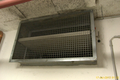
 North American fire dampers, ready for installation in Durasteel fire-resistance rated pressurisation ductwork.
 -
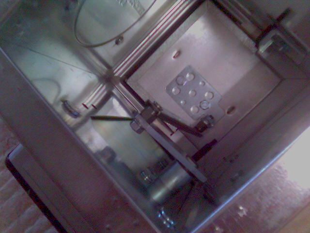
 Side view of North American fire damper, showing the closing mechanism that shuts the interior blades.
 -
 European fire damper with interior fire-resisting board.
 -
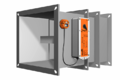
 Fail-safe rotary actuator for fire dampers.
 -
 Fire damper in oversized hole in a 2-hour rated concrete slab.


Mechanical dampers obstruct the cross-sectional area of a HVAC duct in the event of a fire either by means of a pivoting a fire-resistant board in Europe, or steel shutters in North America. Maintenance includes the function of the damper and removal of obstructions that may impair proper function.
Intumescent dampers
[edit]-
 Intumescent damper insert. Openings in the unit swell shut as a result of intumescence in case of fire or heat exposure.
 -
 Round intumescent damper insert.


Intumescent dampers swell shut due to intumescence in the event of a fire. Unlike mechanical dampers, it is a physical/chemical reaction that causes closure. Cleaning and an age assessment are periodically performed. The annulus of an intumescent damper is closed eliminating smoke migration. Also, intumescent fire dampers can be qualified to ASTM E2912.[2] or ISO 10294-5:2005 Fire dampers for air distribution systems—Part 5: Intumescent fire dampers. The purpose of some intumescent fire dampers is to prevent entry of airborne burning embers into buildings as a result of Wildlife Urban Interface Fires (WUI).[3]
Air transfer dampers
[edit]Air transfer fire dampers (ATFD) are not protected by ductwork and must therefore be installed and manufactured to standards and tests that take into account room fire exposures. Air transfer fire dampers are passive such as intumescent types or mechanical types. They are designed for fire resistance, direct flame resistance in the open state or for smoke resistance or for combinations. Some designs are for exterior use, some are for hygienic zone use and some are for Ex-zone applications.
Depending on regional regulation, they are either tested to the same exposure as wall and floor building elements or tested slightly different such as for cable or pipe penetrations. In Europe, Sm or Sa classifications can be obtained for cold smoke resistance or cold and hot smoke resistance respectively. In the US, listing can be issued for use in wildfire exposure.
Contrary to dampers in ducts the closing time of ATFDs are crucial to avoid fire passing during the open state. For applications where direct flame penetration is not allowed through openings that are normally in open state, ATFDs must pass adequate standards. In the US, ASTM E2912 verify direct flame resistance in the open state and ASTM E119 for closed state.
Air transfer fire dampers for walls or floors are usually designed for flush installation and comes in multiple sizes. Dampers are listed for vertical or horizontal installation or both and for one- or two-way fire exposure. Performance may be fire rated resistance as the compartment they serve, with or without smoke resistance. In Europe, the harmonized ETAG 026 Part 4 apply to classification of ATFDs.
-
 Fire element for air transfer dampers for walls
 -
 Air transfer damper mounted in wall


Air transfer fire dampers for doors are designed and tested for use in the lower part of door leaves and cannot be installed elsewhere or higher. In Europe, the fire door test EN 14600 and EN 1634-1 applies.
Air transfer fire dampers in facades are vents applied in wall, eave soffit, gable or foundation. In the US, these are used to protect from exterior fire exposure from neighboring structure or via window-, arson- and wildfire (ASTM E2912 plus ASTM E119) or against wildfire only (ASTM E2886). In Europe, air transfer grilles for walls can be applied externally once a national assessment of suitability for the application in regards of embers, direct flame impingement, environmental impacts etc. has been done.
Ventilating cavity fire barriers is a type of air transfer fire damper used in cavities or voids in constructions with natural ventilation, typically inside air gaps behind cladding. These are often subject to sudden direct flame impingement. In the US, ASTM E2912 cover testing, combined with E119 where required. A method to verify performance in the open state, similar to E2912, is being assessed in Europe by CEN.
-
 Cavity barrier with instant fire stop
 -
 Cavity barrier invisible behind cladding


Dampers for ducts applied as air transfer dampers: Allowances exist for use of duct dampers as air transfer fire dampers. Since these typically will be too hot, and even allow penetration of flames to the unexposed side during fire, they must be modified and classified for such application. To achieve this they are tested with a grid on either side to prevent combustibles to be stored too close to hot parts or flaming. Some jurisdictions prescribe a general grid for use in front of listed duct dampers, which are not listed for use without ductwork.
Fire damper inspections and maintenance
[edit]

In the US, the Joint Commission, State Fire Marshals and Other Authorities Having Jurisdiction (AHJ's), require some Fire and Smoke Dampers to be tested at specified intervals. Similarly, European authorities mandate maintenance and repairs of fire dampers also, as part of approvals or listings issued following successful testing of fire damper assemblies.
See also
[edit]References
[edit]External links
[edit]- NFPA Xchange site on comparison of UL555(S) versus DIN4102 qualified fire dampers, including video link[permanent dead link]
- UL fire damper guideline
- Abstract on UL555 Standard on Fire Dampers
- Abstract on UL555s Standard for Smoke Dampers
- Abstract on UL555c Standard on Ceiling Dampers
- UL Marking and Application Guide for Dampers Archived 2013-12-13 at the Wayback Machine
- Abstract on UL33 Heat Responsive Links for Fire-Protection Service
- ASTM E2912 Standard Test Method for Fire Test of Non-Mechanical Fire Dampers Used in Vented Construction
- ASTM E2886 Access Portal: Standard Test Method for Evaluating the Ability of Exterior Vents to Resist the Entry of Embers and Direct Flame Impingement
- NFPA 80 Access Portal: Standard for Fire Doors and Other Opening Protectives
- NFPA 90A Access: Standard for the Installation of Air-Conditioning and Ventilating Systems
- NFPA 105 Access: Standard for the Installation of Smoke Door Assemblies and Other Opening Protectives
- SMACNA - Fire, Smoke, and Radiation Damper Installation Guide for HVAC (for purchase)
- 14600 Access Portal: Doorsets and openable windows with fire resisting and/or smoke control characteristics - Requirements and classification
- EN 1634-1 Access Portal: Fire resistance and smoke control tests for door and shutter assemblies, openable windows and elements of building hardware - Part 1: Fire resistance test for door and shutter assemblies and openable windows
- Abstract DIN EN 15650:2010-09 Ventilation for buildings - Fire dampers; German version EN 15650:2010
- Abstract DIN EN 15882-2:2010-11 Extended application of results from fire resistance tests for service installations - Part 2 - Dampers; German version prEN 15882-2:2010
- Excerpt Scheuermann, Praxishandbuch Brandschutz (Practice Handbook Fire Protection, Paragraph 5.5.4 Fire Dampers), 2008 Archived 2013-12-12 at the Wayback Machine
- Access to DIN EN 1366-2:1999-10 (replaces DIN4102 Part 6) Fire resistance tests on service installations - Part 2: Fire dampers; German version EN 1366-2:1999
- Abstract ISO 10294-1:1996 Fire resistance tests -- Fire dampers for air distribution systems -- Part 1: Test method
- Abstract ISO 10294-5:2005 Fire dampers for air distribution systems -- Part 5: Intumescent fire dampers
