")
Community hub
Recent from talks
Contribute something
Nothing was collected or created yet.
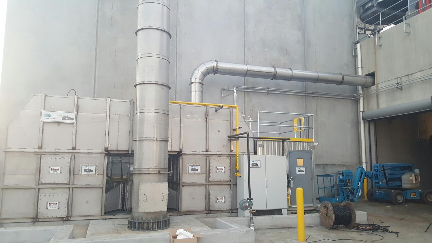
Duct (flow)
View on Wikipedia


Ducts are conduits or passages used in heating, ventilation, and air conditioning (HVAC) to deliver and remove air. The needed airflows include, for example, supply air, return air, and exhaust air.[1] Ducts commonly also deliver ventilation air as part of the supply air. As such, air ducts are one method of ensuring acceptable indoor air quality as well as thermal comfort.
A duct system is also called ductwork. Planning (laying out), sizing, optimizing, detailing, and finding the pressure losses through a duct system is called duct design.[2]
Materials
[edit]Ducts can be made out of the following materials: They are
Galvanized steel
[edit]Galvanized mild steel is the standard and most common material used in fabricating ductwork because the zinc coating of this metal prevents rusting and avoids cost of painting.[3] For insulation purposes, metal ducts are typically lined with faced fiberglass blankets (duct liner) or wrapped externally with fiberglass blankets (duct wrap). When necessary, a double walled duct is used. This will usually have an inner perforated liner, then a 1–2 in (2.5–5.1 cm) layer of fiberglass insulation contained inside an outer solid pipe.
Rectangular ductwork commonly is fabricated to suit by specialized metal shops. For ease of handling, it most often comes in 4 ft (120 cm) sections (or joints). Round duct is made using a continuous spiral forming machine which can make round duct in nearly any diameter when using the right forming die and to any length to suit, but the most common stock sizes range evenly from 4 to 24 in (10 to 61 cm) with 6–12 in (15–30 cm) being most commonly used. Stock pipe is usually sold in 10 ft (300 cm) joints. There are also 5 ft (150 cm) joints of the non-spiral type pipe available, which is commonly used in residential applications.
Aluminium
[edit]Aluminium ductwork is lightweight and quick to install. Also, custom or special shapes of ducts can be easily fabricated in the shop or on site.
The ductwork construction starts with the tracing of the duct outline onto the aluminium preinsulated panel. The parts are then typically cut at 45°, bent if required to obtain the different fittings (i.e. elbows, tapers) and finally assembled with glue. Aluminium tape is applied to all seams where the external surface of the aluminium foil has been cut. A variety of flanges are available to suit various installation requirements. All internal joints are sealed with sealant.
Aluminum is also used to make round spiral duct, but it is much less common than galvanized steel.
Polyurethane and phenolic insulation panels (pre-insulated air ducts)
[edit]Traditionally, air ductwork is made of sheet metal which was installed first and then lagged with insulation. Today, a sheet metal fabrication shop would commonly fabricate the galvanized steel duct and insulate with duct wrap prior to installation. However, ductwork manufactured from rigid insulation panels does not need any further insulation and can be installed in a single step. Both polyurethane and phenolic foam panels are manufactured with factory applied aluminium facings on both sides. The thickness of the aluminium foil can vary from 25 micrometres for indoor use to 200 micrometers for external use or for higher mechanical characteristics. There are various types of rigid polyurethane foam panels available, including water formulated panel for which the foaming process is obtained through the use of water and CO2 instead of CFC, HCFC, HFC and HC gasses. Most manufacturers of rigid polyurethane or phenolic foam panels use pentane as foaming agent instead of the aforementioned gasses.
A rigid phenolic insulation ductwork system is listed as a class 1[clarification needed] air duct to UL 181 Standard for Safety.
Fiberglass duct board (preinsulated non-metallic ductwork)
[edit]Fiberglass duct board panels provide built-in thermal insulation and the interior surface absorbs [sound], helping to provide quiet operation of the HVAC system.
The duct board is formed by sliding a specially designed knife along the board using a straightedge as a guide. The knife automatically trims out a groove with 45° sides which does not quite penetrate the entire depth of the duct board, thus providing a thin section acting as a hinge. The duct board can then be folded along the groove to produce 90° folds, making the rectangular duct shape in the fabricator's desired size. The duct is then closed with outward-clinching staples and special aluminum or similar metal-backed tape.
Flexible ducting
[edit]Flexible ducts (also known as flex) are typically made of flexible plastic over a metal wire coil to shape a tube. They have a variety of configurations. In the United States, the insulation is usually glass wool, but other markets such as Australia, use both polyester fiber and glass wool for thermal insulation. A protective layer surrounds the insulation, and is usually composed of polyethylene or metalized PET. It is commonly sold as boxes containing 25 ft (7.6 m) of duct compressed into a 5 ft (1.5 m) length. It is available in diameters ranging from as small as 4 in (10 cm) to as big as 18 in (46 cm), but the most commonly used are even sizes ranging from 6 to 12 in (15 to 30 cm).
Flexible duct is very convenient for attaching supply air outlets to the rigid ductwork. It is commonly attached with long zip ties or metal band claps. However, the pressure loss is higher than for most other types of ducts. As such, designers and installers attempt to keep their installed lengths (runs) short, e.g. less than 15 feet (4.6 m) or so, and try to minimize turns. Kinks in flexible ducting must be avoided. Some flexible duct markets prefer to avoid using flexible duct on the return air portions of HVAC systems, however flexible duct can tolerate moderate negative pressures. The UL181 test requires a negative pressure of 200 Pa.
To use flexible ducting in a system, make sure to pull the duct tight so you get the full internal diameter. This reduces resistance and improves airflow, as well as ventilation efficiency. Minimize bends and kinks as much as possible, since they can affect how well the airstream flows through the ductwork.
There are a few types of flexible ducting – Polyurethane (PU), Aluminium & Aluminium insulated, Acoustic and Rectangular flexible ducting, as well as semi- and combi-flex.
Fabric ducting
[edit]This is actually an air distribution device and is not intended as a conduit for conditioned air. The term fabric duct is therefore somewhat misleading; fabric air dispersion system would be the more definitive name. However, as it often replaces hard ductwork, it is easy to perceive it simply as a duct. Usually made of polyester material, fabric ducts can provide a more even distribution and blending of the conditioned air in a given space than a conventional duct system. They may also be manufactured with vents or orifices.
Fabric ducts are available in various colors, with options for silk screening or other forms of decoration, or in porous (air-permeable) and non-porous fabric. The determination which fabric is appropriate (i.e. air-permeable or not) can be made by considering if the application would require an insulated metal duct. If so, an air-permeable fabric is recommended because it will not commonly create condensation on its surface and can therefore be used where air is supplied below the dew point. Material that eliminates moisture may be healthier for the occupants. It can also be treated with an anti-microbial agent to inhibit bacterial growth. Porous material also tends to require less maintenance as it repels dust and other airborne contaminants.
Fabric made of more than 50% recycled material is also available, allowing it to be certified as green product. The material can also be fire retardant, which means that the fabric can still burn, but will extinguish when the heat source is removed.
Fabric ducts are not rated for use in ceilings or concealed attic spaces. However, products for use in raised floor applications are available. Fabric ducting usually weighs less than other conventional ducting and will therefore put less stress on the building's structure. The lower weight allows for easier installation.
Fabric ducts require a minimum of certain range of airflow and static pressure in order for it to work.
PVC low-profile ducting
[edit]PVC low-profile ducting has been developed as a cost-effective alternative to steel low-profile ducting. Low-profile ducting has been used extensively in apartment and hotel ventilation since 2005. The growth of low-profile ducting has grown significantly due to the reduction of available space in ceiling cavities in an effort to reduce cost. Since the Grenfell Tower fire in 2017 there has been a rise in the discovery of non-compliant building materials; many PVC low-profile ducting manufacturers have struggled to gain or maintain compliance, and some building projects have had to resort back to using the more expensive steel option.
Waterproofing
[edit]The finish for external ductwork exposed to the weather can be sheet steel coated with aluminium or an aluminium/zinc alloy, a multilayer laminate, a fibre reinforced polymer or other waterproof coating.
Duct system components
[edit]Besides the ducts themselves, complete ducting systems contain many other components.
Vibration isolators
[edit]
A duct system often begins at an air handler. The blowers in the air handler can create substantial vibration, and the large area of the duct system would transmit this noise and vibration to the inhabitants of the building. To avoid this, vibration isolators (flexible sections) are normally inserted into the duct immediately before and after the air handler. The rubberized canvas-like material of these sections allows the air handler to vibrate without transmitting much vibration to the attached ducts. The same flexible section can reduce the noise that can occur when the blower engages and positive air pressure is introduced to the ductwork.
Take-offs
[edit]Downstream of the air handler, the supply air trunk duct will commonly fork, providing air to many individual air outlets such as diffusers, grilles, and registers. When the system is designed with a main duct branching into many subsidiary branch ducts, fittings called take-offs allow a small portion of the flow in the main duct to be diverted into each branch duct. Take-offs may be fitted into round or rectangular openings cut into the wall of the main duct. The take-off commonly has many small metal tabs that are then bent to attach the take-off to the main duct. Round versions are called spin-in fittings. Other take-off designs use a snap-in attachment method, sometimes coupled with an adhesive foam gasket for improved sealing. The outlet of the take-off then connects to the rectangular, oval, or round branch duct.
Stack boots and heads
[edit]Ducts, especially in homes, must often allow air to travel vertically within relatively thin walls. These vertical ducts are called stacks and are formed with either very wide and relatively thin rectangular sections or oval sections. At the bottom of the stack, a stack boot provides a transition from an ordinary large round or rectangular duct to the thin wall-mounted duct. At the top, a stack head can provide a transition back to ordinary ducting while a register head allows the transition to a wall-mounted air register.
Volume control dampers
[edit]
Ducting systems must often provide a method of adjusting the volume of air flow to various parts of the system. Volume control dampers (VCDs; not to be confused with smoke/fire dampers) provide this function. Besides the regulation provided at the registers or diffusers that spread air into individual rooms, dampers can be fitted within the ducts themselves. These dampers may be manual or automatic. Zone dampers provide automatic control in simple systems while variable air volume (VAV) allows control in sophisticated systems.
Smoke and fire dampers
[edit]Smoke dampers and fire dampers are found in ductwork where the duct passes through a firewall or firecurtain.
Smoke dampers are driven by a motor, referred to as an actuator. A probe connected to the motor is installed in the run of the duct and detects smoke, either in the air which has been extracted from or is being supplied to a room, or elsewhere within the run of the duct. Once smoke is detected, the actuator will automatically close the smoke damper until it is manually re-opened.
Fire dampers can be found in the same places as smoke dampers, depending on the application of the area after the firewall. Unlike smoke dampers, they are not triggered by any electrical system (which is an advantage in case of an electrical failure where the smoke dampers would fail to close). Vertically mounted fire dampers are gravity operated, while horizontal fire dampers are spring powered. A fire damper's most important feature is a mechanical fusible link which is a piece of metal that will melt or break at a specified temperature. This allows the damper to close (either from gravity or spring power), effectively sealing the duct, containing the fire, and blocking the necessary air to burn.
Turning vanes
[edit]

Turning vanes are installed inside of ductwork at changes of direction (e.g. at 90° turns) in order to minimize turbulence and resistance to the air flow. The vanes guide the air so it can follow the change of direction more easily.
Plenums
[edit]Plenums are the central distribution and collection units for an HVAC system. The return plenum carries the air from several large return grilles (vents) or bell mouths to a central air handler. The supply plenum directs air from the central unit to the rooms which the system is designed to heat or cool. They must be carefully planned in ventilation design.[why?]
Terminal units
[edit]While single-zone constant air volume systems typically do not have these, multi-zone systems often have terminal units in the branch ducts. Usually there is one terminal unit per thermal zone. Some types of terminal units are VAV boxes (single or dual duct), fan-powered mixing boxes (in parallel or series arrangement), and induction terminal units. Terminal units may also include a heating or cooling coil.
Air terminals
[edit]Air terminals are the supply air outlets and return or exhaust air inlets. For supply, diffusers are most common, but grilles, and for very small HVAC systems (such as in residences) registers are also used widely. Return or exhaust grilles are used primarily for appearance reasons, but some also incorporate an air filter and are known as filter returns.[4]
Duct cleaning
[edit]The position of the U.S. Environmental Protection Agency (EPA) is that "If no one in your household suffers from allergies or unexplained symptoms or illnesses and if, after a visual inspection of the inside of the ducts, you see no indication that your air ducts are contaminated with large deposits of dust or mold (no musty odor or visible mold growth), having your air ducts cleaned is probably unnecessary."[5][needs update][dubious – discuss] However, a study published in Environmental Monitoring and Assessment provides evidence that challenges this position. The study, conducted across eight identical homes, found that HVAC duct cleaning reduced particle counts at the 1.0-micron size and lowered bioaerosol concentrations two days post-cleaning compared to pre-cleaning levels, with the Air Sweep method showing the most significant reduction. This indicates that duct cleaning can effectively decrease certain airborne pollutants, even if contamination isn't visibly obvious or immediately symptomatic. Notably, the study also observed that cleaning processes temporarily increase airborne particles and bioaerosols during the procedure due to disturbance, suggesting that benefits may not be immediate but emerge over time.[6]
A thorough duct cleaning done by a professional duct cleaner will remove dust, cobwebs, debris, pet hair, rodent hair and droppings, paper clips, calcium deposits, children's toys, and whatever else might collect inside. Ideally, the interior surface will be shiny and bright after cleaning. Insulated fiber glass duct liner and duct board can be cleaned with special non-metallic bristles. Fabric ducting can be washed or vacuumed using typical household appliances.
Signs and indicators
[edit]Cleaning of the duct system may be necessary if:
This section needs additional citations for verification. (July 2009) |
- Sweeping and dusting the furniture needs to be done more than usual.
- After cleaning, there is still left over visible dust floating around the house.
- After or during sleep, occupants experience headaches, nasal congestion, or other sinus problems.
- Rooms in the house have little or no air flow coming from the vents.[7][8]
- Occupants are constantly getting sick or are experiencing more allergies than usual.
- There is a musty or stale odor when turning on the furnace or air conditioner.
- Occupants are experiencing signs of sickness, e.g. fatigue, headache, sneezing, stuffy or running nose, irritability, nausea, dry or burning sensation in eyes, nose and throat.
Commercial inspection
[edit]In commercial settings, regular inspection of ductwork is recommended by several standards. One standard recommends inspecting supply ducts every 1–2 years, return ducts every 1–2 years, and air handling units annually.[9] Another recommends visual inspection of internally lined ducts annually[10] Duct cleaning should be based on the results of those inspections.
Inspections are typically visual, looking for water damage or biological growth.[9][10][11] When visual inspection needs to be validated numerically, a vacuum test (VT) or deposit thickness test (DTT) can be performed. A duct with less than 0.75 mg/100m2 is considered to be clean, per the NADCA standard.[11] A Hong Kong standard lists surface deposit limits of 1g/m2 for supply and return ducts and 6g/m2 for exhaust ducts, or a maximum deposit thickness of 60 μm in supply and return ducts, and 180 μm for exhaust ducts.[12] In the UK, CIBSE standard TM26 recommends duct cleaning if measured bacterial content is more than 29 colony forming units (CFU) per 10 cm2; contamination is classified as "low" below 10 CFU/cm2, "medium" at up to 20 CFU/cm2, and "high" when measured above 20 CFU/cm2.[13]
Grants and tax credits
[edit]As of 2025, there are no widely available federal or state grants or tax credits in the U.S. specifically for home duct cleaning or routine maintenance, though related activities might qualify under broader programs. The Weatherization Assistance Program aids low-income households with energy efficiency upgrades like duct sealing,[14] but not cleaning, while the Energy Efficient Home Improvement Credit offers up to $1,200 annually for sealing leaky ducts if it meets energy-saving standards—routine cleaning,[15] however, doesn't qualify.[16] General HVAC maintenance lacks direct incentives; however, installing efficient equipment, such as heat pumps, could yield a separate $2,000 credit.[17][18]
In Canada, financial support for home duct cleaning and maintenance varies by region and eligibility. In Montreal, La Commission des normes, de l'équité, de la santé et de la sécurité du travail (CNESST) offers reimbursements up to $3,897 in 2024 for workers with permanent disabilities from work-related incidents, covering tasks like duct cleaning if they can't perform them due to physical limitations, requiring two quotes for approval.[19] For seniors over 70, Revenu Québec’s Tax Credit for Home Support provides relief on labor costs for services including duct cleaning (without disassembly), aimed at reducing maintenance expenses, claimed via Appendix J or advance payments.[19] Meanwhile, Repentigny’s green initiative reimburses duct cleaning and reusable filter costs to promote eco-friendly living.[19]
Duct sealing
[edit]Air pressure combined with air duct leakage can lead to a loss of energy in a HVAC system. Sealing leaks in air ducts reduces air leakage, optimizes energy efficiency, and controls the entry of pollutants into the building. Before sealing ducts it is imperative to ensure the total external static pressure of the duct work, and if equipment will fall within the equipment manufacturer's specifications. If not, higher energy usage and reduced equipment performance may result.
Commonly available duct tape should not be used on air ducts (metal, fiberglass, or otherwise) that are intended for long-term use. The adhesive on so called duct tape dries and releases with time. A more common type of duct sealant is a water-based paste that is brushed or sometimes sprayed on the seams when the duct is built. Building codes and UL standards call for special fire-resistant tapes, often with foil backings and long lasting adhesives.
Automated technology exists that can seal a duct system in its entirety from the inside out using a patented process and specialized sealant. This method for duct sealing is often used in commercial construction and multi-unit residential construction. The cost associated with automated duct sealing often makes it impractical for the average homeowner to implement in their own house.
Signs of leaks
[edit]Signs of leaky or poorly performing air ducts include:
- Utility bills in winter and summer months above average relative to rate fluctuation
- Spaces or rooms that are difficult to heat or cool
- Duct location in an attic, attached garage, leaky floor cavity, crawl space or unheated basement.[20]
See also
[edit]References
[edit]- ^ The Fundamentals volume of the ASHRAE Handbook, ASHRAE, Inc., Atlanta, GA, USA, 2005
- ^ HVAC Systems – Duct Design, 3rd Ed., SMACNA, 1990
- ^ Deshpande, Prachi; Manjare, Kajal; Bhaisare, Ashish. "Review on Manufacturing Process Study of Ducting used in Industrial and Commercial Application" (PDF). International Journal of Scientific Development and Research. 4 (4): 210. ISSN 2455-2631.
- ^ Designer's Guide to Ceiling-Based Room Air Diffusion, Rock and Zhu, ASHRAE, Inc., Atlanta, GA, USA, 2002
- ^ US EPA, OAR (2014-07-28). "Should You Have the Air Ducts in Your Home Cleaned?". United States Environmental Protection Agency. Retrieved 2022-11-23.
- ^ Ahmad, Irtishad; Tansel, Berrin; Mitrani, Jose D. (2001-12-01). "Effectiveness of HVAC Duct Cleaning Procedures in Improving Indoor Air Quality". Environmental Monitoring and Assessment. 72 (3): 265–276. doi:10.1023/A:1012045104566. ISSN 1573-2959.
- ^ "Should You Have the Air Ducts in Your Home Cleaned?". U.S. Environmental Protection Agency. Retrieved 2025-11-03.
- ^ "Is Duct Cleaning a Waste of Money? Expert Guide & Facts". London Post Daily. 2025-10-28. Retrieved 2025-11-03.
The article explains that duct cleaning may be necessary when airflow feels weak or uneven, or when occupants notice dust, odors, or allergy symptoms.
- ^ a b NADCA (2013). "ACR, The NADCA Standard for Assessment Cleaning Restoration of HVAC Systems" (PDF). National Air Duct Cleaners Association. Archived from the original (PDF) on 11 February 2015. Retrieved 16 June 2014.
- ^ a b ANSI/ASHRAE/ACCA (2012). "Standard 180 Standard Practice for Inspection and Maintenance of Commercial Building HVAC Systems". American Society of Heating Ventilation and Air Conditioning Engineers. Retrieved 16 June 2014.
- ^ a b Willis, Steve. "Verifying System Cleanliness: A Guide for Commissioning Providers" (PDF). www.commissioning.org. American Commissioning Group (ACG). Retrieved 16 June 2014.
- ^ AIIB/ACRA/BSOMES/HKBCxC (2004), A Management Practice Guidance Note on Air Duct Cleaning for Hong Kong, Asian Institute of Intelligent Buildings
- ^ Chartered Institute of Building Service Engineers (October 2000), TM 26: Hygiene Maintenance of Office Ventilation Ductwork
- ^ "Weatherization Assistance Program - Overview" (PDF). U.S. Department of Energy. Retrieved 7 April 2025.
- ^ Hunt, Daphne. "How Duct Work and Sealing is Covered Under the Inflation Reduction Act (IRA)". www.aeheatingandcooling.com. Retrieved 2025-04-07.
- ^ "Insulation Tax Credit | ENERGY STAR". www.energystar.gov. Retrieved 2025-04-07.
- ^ "Federal Tax Credits for Energy Efficiency | ENERGY STAR". www.energystar.gov. Retrieved 2025-04-07.
- ^ Neumann, Johanna; Laureano, Andrea; Casale, Matt (2023-01-26). "Heat pumps: how federal tax credits can help you get one". Environment America Research & Policy Center. Retrieved 2025-04-07.
- ^ a b c Pilon, François (2025-01-06). "Grants and tax credits for home cleaning services in Montreal". Nettoyage Experts | Residential and Commercial Cleaning Services. Retrieved 2025-04-07.
- ^ Ductwork sealing article at Energy Star
- ^ Types of flexible ducting
Further reading
[edit]- Air Diffusion Council Flexible Duct Performance and Installation Standard, 4th Ed., 2003
- Bhatia, A (2020). HVAC Ducting – Principles and Fundamentals (PDF). PDH Center.