

Community hub
Recent from talks
Contribute something
Nothing was collected or created yet.
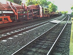
Railway track
View on Wikipedia

| Part of a series on |
| Rail transport |
|---|
|
|
| Infrastructure |
|
|
| Rolling stock |
|
|
| Urban rail transit |
|
|
| Other topics |
|
|
Railway track (CwthE and UIC terminology) or railroad track (NAmE), also known as permanent way (per way) (CwthE)[1] or "P way" (BrE[2] and Indian English), is the structure on a railway or railroad consisting of the rails, fasteners, sleepers (railroad ties in American English) and ballast (or slab track), plus the underlying subgrade. It enables trains to move by providing a dependable, low-friction surface on which steel wheels can roll. Early tracks were constructed with wooden or cast-iron rails, and wooden or stone sleepers. Since the 1870s, rails have almost universally been made from steel.
Historical development
[edit]The first railway in Britain was the Wollaton Wagonway, built in 1603 between Wollaton and Strelley in Nottinghamshire. It used wooden rails and was the first of about 50 wooden-railed tramways built over the subsequent 164 years.[3] These early wooden tramways typically used rails of oak or beech, attached to wooden sleepers with iron or wooden nails. Gravel or small stones were packed around the sleepers to hold them in place and provide a walkway for the people or horses that moved wagons along the track. The rails were usually about 3 feet (0.91 m) long and were not joined - instead, adjacent rails were laid on a common sleeper. The straight rails could be angled at these joints to form primitive curved track.[3]
The first iron rails laid in Britain were at the Darby Ironworks in Coalbrookdale in 1767.[4]
When steam locomotives were introduced, starting in 1804, the track then in use proved too weak to carry the additional weight. Richard Trevithick's pioneering locomotive at Pen-y-darren broke the plateway track and had to be withdrawn. As locomotives became more widespread in the 1810s and 1820s, engineers built rigid track formations, with iron rails mounted on stone sleepers, and cast-iron chairs holding them in place. This proved to be a mistake, and was soon replaced with flexible track structures that allowed a degree of elastic movement as trains passed over them.[3]
Structure
[edit]
Sometimes there is a layer of rubber matting (not shown) to improve drainage, and to dampen sound and vibration
Traditional track structure
[edit]This section possibly contains original research. (August 2022) |
Traditionally, tracks are constructed using flat-bottomed steel rails laid on and spiked or screwed into timber or pre-stressed concrete sleepers (known as ties in North America), with crushed stone ballast placed beneath and around the sleepers.[5][6]
Most modern railroads with heavy traffic use continuously welded rails that are attached to the sleepers with base plates that spread the load. When concrete sleepers are used, a plastic or rubber pad is usually placed between the rail and the tie plate. Rail is usually attached to the sleeper with resilient fastenings, although cut spikes are widely used in North America. For much of the 20th century, rail track used softwood timber sleepers and jointed rails, and a considerable amount of this track remains on secondary and tertiary routes.
In North America and Australia, flat-bottomed rails were typically fastened to the sleepers with dog spikes through a flat tie plate. In Britain and Ireland, bullhead rails were carried in cast-iron chairs which were spiked to the sleepers. In 1936, the London, Midland and Scottish Railway pioneered the conversion to flat-bottomed rail in Britain, though earlier lines had made some use of it.[3]
Jointed rails were used at first because contemporary technology did not offer any alternative. However, the intrinsic weakness in resisting vertical loading results in the ballast becoming depressed and a heavy maintenance workload is imposed to prevent unacceptable geometrical defects at the joints. The joints also needed to be lubricated, and wear at the fishplate (joint bar) mating surfaces needed to be rectified by shimming. For this reason jointed track is not financially appropriate for heavily operated railroads.
Timber sleepers are of many available timbers, and are often treated with creosote, chromated copper arsenate, or other wood preservatives. Pre-stressed concrete sleepers are often used where timber is scarce and where tonnage or speeds are high. Steel is used in some applications.
Track ballast is usually stone crushed to particular specifications. Its purpose is to support the sleepers and allow some adjustment of their position while allowing free drainage.
-
 Traditional railway track showing ballast, sleepers, and rail fixings
 -
 Guideway of the Light Rail Transit system, Singapore, on which rubber-tyred automated people-mover vehicles operate


Ballastless track
[edit]
A disadvantage of traditional track structures is the heavy demand for maintenance, particularly surfacing (tamping) and lining to restore the desired track geometry and smoothness of vehicle running. Weakness of the subgrade and drainage deficiencies also lead to heavy maintenance costs. This can be overcome by using ballastless track. In its simplest form this consists of a continuous slab of concrete (like a highway structure) with the rails supported directly on its upper surface (using a resilient pad).
There are a number of proprietary systems; variations include a continuous reinforced concrete slab and the use of pre-cast pre-stressed concrete units laid on a base layer. Many permutations of design have been put forward.
However, ballastless track has a high initial cost, and in the case of existing railroads the upgrade to such requires closure of the route for a long period. Its whole-life cost can be lower because of the reduction in maintenance. Ballastless track is usually considered for new very high speed or very high loading routes, in short extensions that require additional strength (e.g. railway stations), or for localised replacement where there are exceptional maintenance difficulties, for example in tunnels. Most rapid transit lines and rubber-tyred metro systems use ballastless track.[7]
Continuous longitudinally supported track
[edit]

Early railways (c. 1840s) experimented with continuous bearing railtrack, in which the rail was supported along its length, with examples including Brunel's baulk road on the Great Western Railway, as well as use on the Newcastle and North Shields Railway,[8] on the Lancashire and Yorkshire Railway to a design by John Hawkshaw, and elsewhere.[9] Continuous-bearing designs were also promoted by other engineers.[10] The system was tested on the Baltimore and Ohio railway in the 1840s, but was found to be more expensive to maintain than rail with cross sleepers.[11]
This type of track still exists on some bridges on Network Rail where the timber baulks are called waybeams or longitudinal timbers. Generally the speed over such structures is low.[12]
Later applications of continuously supported track include Balfour Beatty's 'embedded slab track', which uses a rounded rectangular rail profile (BB14072) embedded in a slipformed (or pre-cast) concrete base (development 2000s).[13][14] The 'embedded rail structure', used in the Netherlands since 1976, initially used a conventional UIC 54 rail embedded in concrete, and later developed (late 1990s) to use a 'mushroom' shaped SA42 rail profile; a version for light rail using a rail supported in an asphalt concrete–filled steel trough has also been developed (2002).[15]
Modern ladder track can be considered a development of baulk road. Ladder track utilizes sleepers aligned along the same direction as the rails with rung-like gauge restraining cross members. Both ballasted and ballastless types exist.
Rail
[edit]
Modern track typically uses hot-rolled steel with a profile of an asymmetrical rounded I-beam.[16] Unlike some other uses of iron and steel, railway rails are subject to very high stresses and have to be made of very high-quality steel alloy. It took many decades to improve the quality of the materials, including the change from iron to steel. The stronger the rails and the rest of the trackwork, the heavier and faster the trains the track can carry.[citation needed]
Other profiles of rail include: bullhead rail; grooved rail; flat-bottomed rail (Vignoles rail or flanged T-rail); bridge rail (inverted U–shaped used in baulk road); and Barlow rail (inverted V).
North American railroads until the mid- to late-20th century used rails 39 feet (11.9 m) long so they could be carried in gondola cars (open wagons), often 40 feet (12.2 m) long; as gondola sizes increased, so did rail lengths.
According to the Railway Gazette International the planned-but-cancelled 150-kilometre rail line for the Baffinland Iron Mine, on Baffin Island, would have used older carbon steel alloys for its rails, instead of more modern, higher performance alloys, because modern alloy rails can become brittle at very low temperatures.[17]
Iron-topped wooden rails
[edit]Early North American railroads used iron on top of wooden rails as an economy measure but gave up this method of construction after the iron came loose, began to curl, and intruded into the floors of the coaches, leading early railroaders to refer to them as "snake heads".[18][19]
The Deeside Tramway in North Wales used this form of rail. It opened around 1870 and closed in 1947, with long sections still using these rails. It was one of the last uses of iron-topped wooden rails.[20]
Rail classification (weight)
[edit]Rail is graded by its linear density, that is, its mass over a standard length. Heavier rail can support greater axle loads and higher train speeds without sustaining damage than lighter rail, but at a greater cost. In North America and the United Kingdom, rail is graded in pounds per yard (usually shown as pound or lb), so 130-pound rail would weigh 130 lb/yd (64 kg/m). The usual range is 115 to 141 lb/yd (57 to 70 kg/m). In Europe, rail is graded in kilograms per metre and the usual range is 40 to 60 kg/m (81 to 121 lb/yd). The heaviest mass-produced rail was 155 pounds per yard (77 kg/m), rolled for the Pennsylvania Railroad.[citation needed]
Rail lengths
[edit]The rails used in rail transport are produced in sections of fixed length. Rail lengths are made as long as possible, as the joints between rails are a source of weakness. Throughout the history of rail production, lengths have increased as manufacturing processes have improved.
Timeline
[edit]The following are lengths of single sections produced by steel mills, without any thermite welding. Shorter rails may be welded with flashbutt welding, but the following rail lengths are unwelded.
- (1767)
 Richard Reynolds laid the first iron rails at Coalbrookdale.[21]
 - (1825) 15 feet (4.57 m) Stockton and Darlington Railway 5.6 lb/yd (2.78 kg/m)
- (1830) 15 feet (4.57 m) Liverpool and Manchester Railway. Fish-belly rails at 35 lb/yd (17.4 kg/m), laid mostly on stone blocks
- (1831)
 15 feet (4.6 m) long and weighing 36 pounds per yard (17.9 kg/m), reached Philadelphia the first use of the flanged T-rail in the United States
 - (1880)
 39 feet (11.89 m) United States to suit 40-foot-long (12.19 m) gondola cars
 - (1928) 45 and 60 feet (13.72 and 18.29 m) London, Midland and Scottish Railway[22]
- (1950) 60 feet (18.29 m) British Rail
- (1900) 71 ft (21.6 m) – steel works weighing machine for rails (steelyard balance)[23]
- (1940s)
 78 feet (23.77 m) – double 39 ft[24]
 - (1953)
 45 feet (13.72 m) Australia[25]
Welding of rails into longer lengths was first introduced around 1893, making train rides quieter and safer. With the introduction of thermite welding after 1899, the process became less labour-intensive, and ubiquitous.[26]
- (1895)
 Hans Goldschmidt developed exothermic welding
 - (1899) the Essen Tramway became the first railway to use thermite welding; also suited track circuits
- (1904)
 George Pellissier welded the Holyoke Street Railway, first to use the process in the Americas
 - (1935) Charles Cadwell developed non-ferrous exothermic welding
- (1950) 240 ft (73.2 m) welded – (4 x 60 feet or 18.3 metres)[27]
Modern production techniques allowed the production of longer unwelded segments.
- (2007) 108 metres (354.3 ft) Corus (now British Steel (2016–present)[28])
- (2011)
 108 metres (354.3 ft) Tata Steel Europe[29]
 - (2011)
 120 metres (393.7 ft) Voestalpine,[30]
 - (2011)
 121 metres (397.0 ft) Jindal[31]
 - (2014)
 150 metres (492.1 ft) Nippon Steel[32]
Multiples
[edit]Newer longer rails tend to be made as simple multiples of older shorter rails, so that old rails can be replaced without cutting and the same wagons can be used for transportation.[clarification needed] Some cutting would be needed as slightly longer rails are needed on the outside of sharp curves compared to the rails on the inside.[citation needed]
Boltholes
[edit]Rails can be supplied pre-drilled with boltholes for fishplates or without where they will be welded into place. There are usually two or three boltholes at each end.[citation needed]
Joining rails
[edit]Rails are produced in fixed lengths and need to be joined end-to-end to make a continuous surface on which trains may run. The traditional method of joining the rails is to bolt them together using metal fishplates (jointbars in the US), producing jointed track. For more modern usage, particularly where higher speeds are required, the lengths of rail may be welded together to form continuous welded rail (CWR).
Jointed track
[edit]
Jointed track is made using lengths of rail, usually about 20 m (66 ft) long (in the UK) and 39 or 78 ft (12 or 24 m) long (in North America), bolted together using perforated steel plates known as fishplates (UK) or joint bars (North America).
Fishplates are usually 600 mm (2 ft) long, used in pairs either side of the rail ends and bolted together (usually four, but sometimes six bolts per joint). The bolts have alternating orientations so that in the event of a derailment and a wheel flange striking the joint, only some of the bolts will be sheared, reducing the likelihood of the rails misaligning with each other and worsening the derailment. This technique is not applied universally; European practice is to have all the bolt heads on the same side of the rail.
Small gaps which function as expansion joints are deliberately left between the rail ends to allow for expansion of the rails in hot weather. European practice was to have the rail joints on both rails adjacent to each other; North American practice is to stagger them. Because of these small gaps, when trains pass over jointed tracks they make a "clickety-clack" sound, and in time the rail ends are deflected downwards. Unless it is well-maintained, jointed track does not have the ride quality of welded rail and is not suitable for high speed trains. However, jointed track is still used in many countries on lower-speed lines and sidings, and is used extensively in poorer countries due to the lower construction cost and the simpler equipment required for its installation and maintenance.
A major problem of jointed track is cracking around the bolt holes, which can lead to breaking of the rail head (the running surface). This was the cause of the Hither Green rail crash which caused British Railways to begin converting much of its track to continuous welded rail.
Insulated joints
[edit]Where track circuits exist for signalling purposes, insulated block joints are required. These compound the weaknesses of ordinary joints. Specially-made glued joints, where all the gaps are filled with epoxy resin, increase the strength again.
As an alternative to the insulated joint, audio frequency track circuits can be employed using a tuned loop formed in approximately 20 m (66 ft) of the rail as part of the blocking circuit. Some insulated joints are unavoidable within turnouts.
Another alternative is an axle counter, which can reduce the number of track circuits and thus the number of insulated rail joints required.
Continuous welded rail
[edit]

Most modern railways use continuous welded rail, sometimes referred to as ribbon rails or seamless rails. In this form of track, the rails are welded together by utilising flash butt welding to form one continuous rail that may be several kilometres long. Because there are few joints, this form of track is very strong, gives a smooth ride, and needs less maintenance; trains can travel on it at higher speeds and with less friction. Welded rails are more expensive to lay than jointed tracks, but have much lower maintenance costs. The first welded track was used in Germany in 1924.[33] and has become common on main lines since the 1950s.
The preferred process of flash butt welding involves an automated track-laying machine running a strong electric current through the touching ends of two unjoined rails. The ends become white hot due to electrical resistance and are then pressed together forming a strong weld. Thermite welding is used to repair or splice together existing continuous welded rail segments. This manual process requires a reaction crucible and form to contain the molten iron.
North American practice is to weld 1⁄4-mile-long (400 m) segments of rail at a rail facility and load it on a special train to carry it to the job site. This train is designed to carry many segments of rail which are placed so they can slide off their racks to the rear of the train and be attached to the ties (sleepers) in a continuous operation.[34]
If not restrained, rails would lengthen in hot weather and shrink in cold weather. To provide this restraint, the rail is prevented from moving in relation to the sleeper by use of clips or anchors. Attention needs to be paid to compacting the ballast effectively, including under, between, and at the ends of the sleepers, to prevent the sleepers from moving. Anchors are more common for wooden sleepers, whereas most concrete or steel sleepers are fastened to the rail by special clips that resist longitudinal movement of the rail. There is no theoretical limit to how long a welded rail can be. However, if longitudinal and lateral restraint are insufficient, the track could become distorted in hot weather and cause a derailment. Distortion due to heat expansion is known in North America as sun kink, and elsewhere as buckling. In extreme hot weather special inspections are required to monitor sections of track known to be problematic. In North American practice, extreme temperature conditions will trigger slow orders to allow for crews to react to buckling or "sun kinks" if encountered.[35] The German railway company Deutsche Bahn is starting to paint rails white to lower the peak temperatures reached in summer days.[36]
After new segments of rail are laid, or defective rails replaced (welded-in), the rails can be artificially stressed if the temperature of the rail during laying is cooler than what is desired. The stressing process involves either heating the rails, causing them to expand,[37] or stretching the rails with hydraulic equipment. They are then fastened (clipped) to the sleepers in their expanded form. This process ensures that the rail will not expand much further in subsequent hot weather. In cold weather the rails try to contract, but because they are firmly fastened, cannot do so. In effect, stressed rails are a bit like a piece of stretched elastic firmly fastened down. In extremely cold weather, rails are heated to prevent "pull aparts".[38]
Continuous welded rails, complete with fastenings, are laid at a temperature known as "rail neutral temperature" that is approximately midway between the extremes experienced at that location. This installation procedure is intended to prevent tracks from buckling in summer heat or pulling apart in the winter cold. In North America, because broken rails are typically detected by interruption of the current in the signaling system, they are seen as less of a potential hazard than undetected heat kinks.

Joints are used in the continuous welded rail when necessary, usually for signal circuit gaps. Instead of a joint that passes straight across the rail, the two rail ends are sometimes cut at an angle to give a smoother transition. In extreme cases, such as at the end of long bridges, a breather switch (referred to in North America and Britain as an expansion joint) gives a smooth path for the wheels while allowing the end of one rail to expand relative to the next rail.
Sleepers
[edit]A sleeper (tie or crosstie) is a rectangular object on which the rails are supported and fixed. The sleeper has two main roles: to transfer the loads from the rails to the track ballast and the ground underneath, and to hold the rails to the correct width apart (to maintain the rail gauge). They are generally laid transversely to the rails.
Fixing rails to sleepers
[edit]Various methods exist for fixing the rail to the sleeper. Historically, rails were spiked directly on to ties, the practice giving way baseplates being fitted between the rails and sleepers; subsequently, spikes were replaced by sprung steel clips, such as Pandrol clips, to fix the rail to the baseplates.
Portable track
[edit]
Sometimes rail tracks are designed to be portable and moved from one place to another as required. During construction of the Panama Canal, tracks were moved around excavation works. These track gauge were 5 ft (1,524 mm) and the rolling stock full size. Portable tracks have often been used in open pit mines. In 1880 in New York City, sections of heavy portable track (along with much other improvised technology) helped in the move of the ancient obelisk in Central Park to its final location from the dock where it was unloaded from the cargo ship SS Dessoug.
Cane railways often had permanent tracks for the main lines, with portable tracks serving the canefields themselves. These tracks were narrow-gauge (for example, 2 ft (610 mm)) and the portable track came in straights, curves, and turnouts, rather like on a model railway.[39]
Decauville was a source of many portable light rail tracks, also used for military purposes. The permanent way is so called because temporary way tracks were often used in the construction of that permanent way.[40]
Layout
[edit]The geometry of the tracks is three-dimensional by nature, but the standards that express the speed limits and other regulations in the areas of track gauge, alignment, elevation, curvature and track surface are usually expressed in two separate layouts for horizontal and vertical.
Horizontal layout is the track layout on the horizontal plane. This involves the layout of three main track types: tangent track (straight line), curved track, and track transition curve (also called transition spiral or spiral) which connects between a tangent and a curved track.
Vertical layout is the track layout on the vertical plane including the concepts such as crosslevel, cant and gradient.[41][42]
A sidetrack is a railroad track other than siding that is auxiliary to the main track. The word is also used as a verb (without object) to refer to the movement of trains and railcars from the main track to a siding, and in common parlance to refer to giving in to distractions apart from a main subject.[43] Sidetracks are used by railroads to order and organise the flow of rail traffic.
Gauge
[edit]
During the early days of rail, there was considerable variation in the gauge used by different systems, and in the UK during the railway building boom of the 1840s Brunel's broad gauge of 7 ft 1⁄4 in (2,140 mm) was in competition with what was referred to at the time as the 'narrow' gauge of 1,435 mm (4 ft 8+1⁄2 in). Eventually the 1,435 mm (4 ft 8+1⁄2 in) gauge won the battle, and became the standard gauge, with the term 'narrow gauge' henceforth used for gauges narrower than the new standard. As of 2017[update], about 60% of the world's railways use a gauge of 1,435 mm (4 ft 8+1⁄2 in), known as standard or international gauge[44][45] Gauges wider than standard gauge are called broad gauge; narrower, narrow gauge. Some stretches of track are dual gauge, with three (or sometimes four) parallel rails in place of the usual two, to allow trains of two different gauges to use the same track.[46]
Gauge can safely vary over a range. For example, U.S. federal safety standards allow standard gauge to vary from 4 ft 8 in (1,420 mm) to 4 ft 9+1⁄2 in (1,460 mm) for operation up to 60 mph (97 km/h).[47]
Maintenance
[edit]
Track needs regular maintenance to remain in good order, especially when high-speed trains are involved. Inadequate maintenance may lead to a "slow order" (North American terminology, or temporary speed restriction in the United Kingdom) being imposed to avoid accidents (see Slow zone). Track maintenance was at one time hard manual labour, requiring teams of labourers, or trackmen (US: gandy dancers; UK: platelayers; Australia: fettlers or packers) under the supervision of a skilled ganger, who used lining bars to correct irregularities in horizontal alignment (line) of the track, and tamping and jacks to correct vertical irregularities (surface). Currently, maintenance is facilitated by a variety of specialised machines.

The surface of the head of each of the two rails can be maintained by using a railgrinder.
Common maintenance jobs include changing sleepers, lubricating and adjusting switches, tightening loose track components, and surfacing and lining track to keep straight sections straight and curves within maintenance limits. The process of sleeper and rail replacement can be automated by using a track renewal train.
Spraying ballast with herbicide to prevent weeds growing through and redistributing the ballast is typically done with a special weed killing train.
Over time, ballast is crushed or moved by the weight of trains passing over it, periodically requiring relevelling ("tamping") and eventually to be cleaned or replaced. If this is not done, the tracks may become uneven, causing swaying, rough riding and possibly derailments. An alternative to tamping is to lift the rails and sleepers and reinsert the ballast beneath. For this, specialist "stoneblower" trains are used.
Rail inspections utilize nondestructive testing methods to detect internal flaws in the rails. This is done by using specially equipped HiRail trucks, inspection cars, or in some cases, handheld inspection devices.
Rails must be replaced before the railhead profile wears to a degree that may trigger a derailment. Worn mainline rails usually have sufficient life remaining to be used on a branch line, siding or stub afterwards and are "cascaded" to those applications.
The environmental conditions along railroad track create a unique railway ecosystem. This is particularly so in the United Kingdom, where steam locomotives are only used on special services and vegetation has not been trimmed back so thoroughly. This creates a fire risk in prolonged dry weather.
In the UK, the cess is used by track repair crews to walk to a work site, and as a safe place to stand when a train is passing. This helps when doing minor work, while needing to keep trains running, by not needing a Hi-railer or transport vehicle blocking the line to transport crew to get to the site.
-
 Maintenance of way equipment in Italy
 -
-
 Plasser & Theurer 09-32 CSM continuous action levelling, lining and tamping machine of the Romanian Railways


Bed and foundation
[edit]
Railway tracks are generally laid on a bed of stone track ballast or track bed, which in turn is supported by prepared earthworks known as the track formation. The formation comprises the subgrade and a layer of sand or stone dust (often sandwiched in impervious plastic), known as the blanket, which restricts the upward migration of wet clay or silt. There may also be layers of waterproof fabric to prevent water penetrating to the subgrade. The track and ballast form the permanent way. The foundation may refer to the ballast and formation, i.e. all man-made structures below the tracks.
Some railroads are using asphalt pavement below the ballast in order to keep dirt and moisture from moving into the ballast and spoiling it. The fresh asphalt also serves to stabilize the ballast so it does not move around so easily.[48]
Additional measures are required where the track is laid over permafrost, such as on the Qingzang Railway in Tibet. For example, transverse pipes through the subgrade allow cold air to penetrate the formation and prevent that subgrade from melting.
Geosynthetic reinforcement
[edit]Geosynthetics are used to reduce or replace traditional layers in trackbed construction and rehabilitation worldwide to improve track support and reduce track maintenance costs.[49][50] Reinforcement geosynthetics, such as geocells[51] (which rely on 3D soil confinement mechanisms) have demonstrated efficacy in stabilizing soft subgrade soils and reinforcing substructural layers to limit progressive track degradation. Reinforcement geosynthetics increase soil bearing capacity, limit ballast movement and degradation and reduce differential settlement that affects track geometry.[52] They also reduce construction time and cost, while reducing environmental impact and carbon footprint.[53] The increased use of geosynthetic reinforcement solutions is supported by new high-performance geocell materials (e.g., NPA - Novel Polymeric Alloy), published research, case studies projects and international standards (ISO,[54] ASTM,[55] CROW/SBRCURnet[56])
The hybrid use of high-performance geogrids at the subgrade and high-performance geocell in the upper subbase/subballast layer has been shown to increase the reinforcement factor greater than their separate sums, and is particularly effective in attenuating heaving of expansive subgrade clay soils.[57] A field test project on Amtrak's NE Corridor suffering clay mud-pumping demonstrated how the hybrid solution improved track quality index (TQI) significantly reduced track geometry degradation and lowered track surface maintenance by factor of 6.7x utilizing high-performance NPA geocell.[58] Geosynthetic reinforcement is also used to stabilize railway embankments, which must be robust enough to withstand repeated cyclical loading. Geocells can utilize recycled marginal or poorly graded granular material to create stable embankments, make railway construction more economical and sustainable.[59][60][61]
Buses
[edit]
Some buses can use tracks. This concept came out of Germany and was called O-Bahn. The first such track, the O-Bahn Busway, was built in Adelaide, Australia.
See also
[edit]- Degree of curvature
- Difference between train and tram rails
- Exothermic welding
- Gauntlet track
- Glossary of rail terminology
(including US/UK and other
regional/national differences) - Green track
- Maglev
- Minimum railway curve radius
- Monorail
- Permanent way (history)
- Rack railway
- Rail profile
- Roll way, part of the track of a rubber-tyred metro[62]
- Rubber-tyred metro
- Street running
- Subgrade
- Tie plate
- TGV track construction
- Tramway (industrial)
- Tramway track
References
[edit]- ^ W. S. Ramson, ed. (1988). The Australian National Dictionary. Oxford University Press. p. 473. ISBN 0195547365.
- ^ Iain Ellis, ed. (2010). Ellis' British Railway Engineering Encyclopaedia. lulu.com. p. 291. ISBN 978-1-4461-8190-4.
- ^ a b c d Dow, Andrew (30 October 2014). The Railway: British Track Since 1804. Barnsley: Pen & Sword Transport. ISBN 9781473822573.
- ^ "Railways in Britain". Quakers in the World.
- ^ Connor, Piers (10 May 2017). "Track Basics" (PDF). Railway Technical Website. Retrieved 2 September 2022.
- ^ Departments of the Army and the Air Force (8 April 1991). Railroad Track Standards (PDF). Washington, D.C. pp. 3-1 – 7-4.
{{cite book}}: CS1 maint: location missing publisher (link) - ^ "Showing part of the track". Archived from the original on 16 June 2016. Retrieved 7 December 2016.
- ^ Morris, Ellwood (1841), "On Cast Iron Rails for Railways", American Railroad Journal and Mechanic's Magazine, 13 (7 new series): 270–277, 298–304, archived from the original on 11 June 2016, retrieved 20 November 2015
- ^ Hawkshaw, J. (1849). "Description of the Permanent Way, of the Lancashire and Yorkshire, the Manchester and Southport, and the Sheffield, Barnsley and Wakefield Railways". Minutes of the Proceedings. 8 (1849): 261–262. doi:10.1680/imotp.1849.24189. Archived from the original on 24 April 2016. Retrieved 20 November 2015.
- ^ Reynolds, J. (1838). "On the Principle and Construction of Railways of Continuous Bearing. (Including Plate)". ICE Transactions. 2: 73–86. doi:10.1680/itrcs.1838.24387. Archived from the original on 3 June 2016. Retrieved 20 November 2015.
- ^ "Eleventh Annual Report (1848)", Annual report[s] of the Philadelphia, Wilmington and Baltimore Rail Road Company, vol. 4, pp. 17–20, 1842, archived from the original on 28 May 2016, retrieved 20 November 2015
- ^ "Waybeams at KEB, Newcastle Archived 3 September 2020 at the Wayback Machine, Network Rail Media Centre, Retrieved 21 January 2020
- ^ 2.3.3 Design and Manufacture of Embedded Rail Slab Track Components (PDF), Innotrack, 12 June 2008, archived from the original (PDF) on 5 March 2016, retrieved 14 August 2012
- ^ "Putting slab track to the test", www.railwaygazette.com, 1 October 2002, archived from the original on 12 December 2012, retrieved 14 August 2012
- ^ Esveld, Coenraad (2003), "Recent developments in slab track" (PDF), European Railway Review (2): 84–5, archived (PDF) from the original on 20 December 2016, retrieved 14 August 2012
- ^ A Metallurgical History of Railmaking Slee, David E. Australian Railway History, February, 2004 pp43-56
- ^ Carolyn Fitzpatrick (24 July 2008). "Heavy haul in the high north". Railway Gazette International. Archived from the original on 1 May 2009. Retrieved 10 August 2008.
Premium steel rails will not be used, because the material has an increased potential to fracture at very low temperatures. Regular carbon steel is preferred, with a very high premium on the cleanliness of the steel. For this project, a low-alloy rail with standard strength and a Brinell hardness in the range of 300 would be most appropriate.
- ^ ""Snake heads" held up early traffic". Syracuse Herald-Journal. Syracuse, NY. 20 March 1939. p. 77. Archived from the original on 25 May 2018. Retrieved 25 May 2018 – via Newspapers.com.

- ^ "Snakeheads on antebellum railroads". Frederick Jackson Turner Overdrive. 6 February 2012. Archived from the original on 18 October 2016. Retrieved 29 June 2017.
- ^ Jones, Alun (2001). The Slate Railways of Wales. Gwasg Carreg Gwalch.
- ^ Smiles, Samuel. Industrial Biography: Iron Workers and Tool Makers.
- ^ LMS Drawings of Standard Railway Equipment Permanent Way 1928 (The LMS Society - Resources)
- ^ "Big Weighing Machines". Australian Town and Country Journal (NSW : 1870–1907). NSW. 4 August 1900. p. 19. Archived from the original on 20 April 2021. Retrieved 8 October 2011 – via National Library of Australia.
- ^ McGonigal, Robert (1 May 2014). "Rail". ABC's of Railroading. Trains. Archived from the original on 11 September 2014. Retrieved 10 September 2014.
- ^ "Surveys Of New Rail Link". The Advertiser. Adelaide, SA. 17 June 1953. p. 5. Archived from the original on 20 April 2021. Retrieved 3 October 2012 – via National Library of Australia.
- ^ "Thermit®". Evonik Industries. Evonik Industries AG. Archived from the original on 9 May 2019. Retrieved 9 May 2019.
- ^ "Opening Of S.-E. Broad Gauge line". The Advertiser. Adelaide, SA. 2 February 1950. p. 1. Archived from the original on 20 April 2021. Retrieved 8 December 2011 – via National Library of Australia.
- ^ "Production of long-welded and continuous-welded rail". www.railtechnologymagazine.com. Retrieved 4 January 2024.
- ^ "Tata Steel unveils upgraded rail manufacturing plant in France". Tata Steel in Europe. Retrieved 4 January 2024.
- ^ "Ultra-long rails". voestalpine. voestalpine AG. Archived from the original on 10 September 2014. Retrieved 10 September 2014.
- ^ "Rails". Jindal Steel & Power Ltd. Archived from the original on 10 September 2014. Retrieved 10 September 2014.
- ^ "NSSMC Is Ready to Manufacture and Ship the World Longest Railway Rails: 150-Meter Rails". www.nipponsteel.com. Retrieved 18 March 2025.
- ^ C. P. Lonsdale (September 1999). "Thermite Rail Welding: History, Process Developments, Current Practices And Outlook For The 21st Century" (PDF). Proceedings of the AREMA 1999 Annual Conferences. The American Railway Engineering and Maintenance-of-Way Association. p. 2. Archived (PDF) from the original on 10 October 2008. Retrieved 6 July 2008.
- ^ "Welded Rail Trains, CRHS Conrail Photo Archive". conrailphotos.thecrhs.org. 3 October 2009. Archived from the original on 7 November 2017. Retrieved 27 June 2017.
- ^ Bruzek, Radim; Trosino, Michael; Kreisel, Leopold; Al-Nazer, Leith (2015). "Rail Temperature Approximation and Heat Slow Order Best Practices". 2015 Joint Rail Conference. pp. V001T04A002. doi:10.1115/JRC2015-5720. ISBN 978-0-7918-5645-1. Archived from the original on 20 April 2021. Retrieved 27 June 2017.
- ^ "Cooling paintcover for rails". Archived from the original on 20 January 2021. Retrieved 31 March 2021.
- ^ "Continuous Welded Rail". Grandad Sez: Grandad's Railway Engineering Section. Archived from the original on 18 February 2006. Retrieved 12 June 2006.
- ^ Holder, Sarah (30 January 2018). "In Case of Polar Vortex, Light Chicago's Train Tracks on Fire". CityLab. Atlantic Media. Archived from the original on 31 January 2019. Retrieved 30 January 2019.
- ^ Narrow Gauge Down Under magazine, January 2010, p. 20.
- ^ Cole, William Henry (1915). Permanent-way Material, Platelaying, and Points and Crossings. R. & F.N. Spon. p. 1.
- ^ PART 1025 Track Geometry (Issue 2 – 07/10/08 ed.). Department of Planning Transport, and Infrastructure - Government of South Australia. 2008. Archived from the original on 28 April 2013. Retrieved 19 November 2012.
- ^ Track Standards Manual - Section 8: Track Geometry (PDF). Railtrack PLC. December 1998. Archived (PDF) from the original on 29 March 2014. Retrieved 13 November 2012.
- ^ "Dictionary.com". Archived from the original on 4 March 2016. Retrieved 17 July 2017.
- ^ "Dual gauge (1435mm-1520 mm) railway track on the Hungary-Ukraine border - Inventing Europe". www.inventingeurope.eu. Archived from the original on 5 June 2020. Retrieved 1 October 2019.
- ^ ChartsBin. "Railway Track Gauges by Country". ChartsBin. Archived from the original on 1 October 2019. Retrieved 1 October 2019.
- ^ "Message in the mailing list '1520mm' on Р75 rails". Archived from the original on 5 July 2009. Retrieved 16 March 2007.
- ^ Part 13 — Track Safety Standards: Title 49, Transportation - Code of Federal Regulations (PDF) (Report). Office of the Federal Register, National Archives and Records Administration. 10 January 2011. p. 7. Retrieved 14 January 2024.
- ^ "Hot Mix Asphalt Railway Trackbeds: Trackbed Materials, Performance Evaluations, and Significant Implications" (PDF). web.engr.uky.edu. Archived (PDF) from the original on 21 January 2019. Retrieved 21 January 2019.
- ^ Geosynthetics for Development of Transportation Infrastructures. Frontiers Research Topics. 2021. doi:10.3389/978-2-88966-741-3. ISBN 9782889667413.
- ^ Geosynthetics in Railways: Applications & Benefits. International Geosynthetics Society. https://igs2.wpengine.com/wp-content/uploads/2021/04/IGS_Geosynthetics_Railways_Leaflet.pdf. Accessed 28 JUN 2022.
- ^ Leshchinsky, B. (2011) Enhancing Ballast Performance using Geocell Confinement. Advances in Geotechnical Engineering, publication of Geo-Frontiers 2011 conference, Dallas, Texas, USA, March 13–16.
- ^ Zarembski, Allan M.; Palese, Joseph; Hartsough, Christopher M.; Ling, Hoe I.; Thompson, Hugh (2017). "Application of Geocell Track Substructure Support System to Correct Surface Degradation Problems Under High-Speed Passenger Railroad Operations". Transportation Infrastructure Geotechnology. 4 (4): 106–125. Bibcode:2017TrIG....4..106Z. doi:10.1007/s40515-017-0042-x. S2CID 256401992.
- ^ Pokharel, S.K.; Norouzi, M.; Martin, I.; Breault, M. (4 June 2016). "Sustainable road construction for heavy traffic using high strength polymeric geocells" (PDF). Canadian Society of Civil Engineers Annual Conference on Resilient Infrastructure. London, Ontario.
- ^ ISO Standard WD TR 18228-5. (2018). Design using Geosynthetics – Part 5: Stabilization. International Organization for Standardization. Geneva, Switzerland. Under development.
- ^ "Standard Guide for the Use of Geocells in Geotechnical and Roadway Projects". ASTM. 12 August 2021. doi:10.1520/D8269-21.
- ^ Vega, E., van Gurp, C., Kwast, E. (2018). Geokunststoffen als Funderingswapening in Ongebonden Funderingslagen (Geosynthetics for Reinforcement of Unbound Base and Subbase Pavement Layers), CROW/SBRCURnet, Netherlands. Publication C1001 (Dutch).
- ^ Kief, O. (2016) Rail Track Pavements on Expansive Clay Restrained by Hybrid Geosynthetic Solution. Geosynthetics 2016 Conference Proceedings. Miami Beach, FL. April.
- ^ Palese, J.W., Zarembski, A.M., Thompson, H., Pagano, W., and Ling, H.I. (2017). Life Cycle Benefits of Subgrade Reinforcement Using Geocell on a Highspeed Railway – a Case Study. AREMA Conference Proceedings (American Railway Engineering and Maintenance-of-Way Association). Indianapolis, IN, USA, September.
- ^ Pokharel, Sarah; Breault, Marc (1 June 2021). "NPA Geocell for Railway Line Repair in Permafrost Region". Geosynthetics Magazine Online. Industrial Fabrics Association International. ISSN 0882-4983. Retrieved 29 June 2022.
- ^ Das, Braja M. (2016). "Use of geogrid in the construction of railroads". Innovative Infrastructure Solutions. 1 (1) 15. Bibcode:2016InnIS...1...15D. doi:10.1007/s41062-016-0017-8. S2CID 114993446.
- ^ Skok, D.M. and Russo, C. (2020) Embankment Foundation of Sant Martin Railway Viaduct, GeoAmericas 2020, October 26–29, Rio de Janeiro.
- ^ "runway (roll way)". Archived from the original on 16 June 2016. Retrieved 7 December 2016.
Bibliography
[edit]- Pike, J., (2001), Track, Sutton Publishing, ISBN 0-7509-2692-9
- Firuziaan, Mohammad; von Estorff, Otto (October 2002). "Simulation of the Dynamic Behavior of Bedding-Foundation-Soil in the Time Domain". System Dynamics and Long-Term Behaviour of Railway Vehicles, Track and Subgrade. Springer Verlag. pp. 357–376. doi:10.1007/978-3-540-45476-2_21. ISBN 978-3-540-43892-2.
- Robinson, A.M. (2009). Fatigue in railway infrastructure. Woodhead Publishing Limited. ISBN 978-1-85573-740-2.
- Lewis, R (2009). Wheel/rail interface handbook. Woodhead Publishing Limited. ISBN 978-1-84569-412-8.
- Esveld, Coenraad (2001). Modern Railway Track. The Netherlands: MRT-Productions. ISBN 90-800324-3-3.
External links
[edit]- Table of North American tee rail (flat bottom) sections
- ThyssenKrupp handbook, Vignoles rail
- ThyssenKrupp handbook, Light Vignoles rail
- Track Details in photographs
- "Drawing of England Track Laying in Sections at 200 yards an hour" Popular Mechanics, December 1930
- Winchester, Clarence, ed. (1936), "The permanent way", Railway Wonders of the World, pp. 331–338 illustrated description of the construction and maintenance of the railway
- Railway technical Archived 3 May 2017 at the Wayback Machine
| International | |
|---|---|
| National | |
| Other | |