Recent from talks
Contribute something
Nothing was collected or created yet.
Program counter
View on WikipediaThis article needs additional citations for verification. (February 2025) |

The program counter (PC),[1] commonly called the instruction pointer (IP) in Intel x86 and Itanium microprocessors, and sometimes called the instruction address register (IAR),[2][1] the instruction counter,[3] or just part of the instruction sequencer,[4] is a processor register that indicates where a computer is in its program sequence.[5][nb 1]
Usually, the PC is incremented after fetching an instruction, and holds the memory address of ("points to") the next instruction that would be executed.[6][nb 2]
Processors usually fetch instructions sequentially from memory, but control transfer instructions change the sequence by placing a new value in the PC. These include branches (sometimes called jumps), subroutine calls, and returns. A transfer that is conditional on the truth of some assertion lets the computer follow a different sequence under different conditions.
A branch provides that the next instruction is fetched from elsewhere in memory. A subroutine call not only branches but saves the preceding contents of the PC somewhere. A return retrieves the saved contents of the PC and places it back in the PC, resuming sequential execution with the instruction following the subroutine call.
Hardware implementation
[edit]
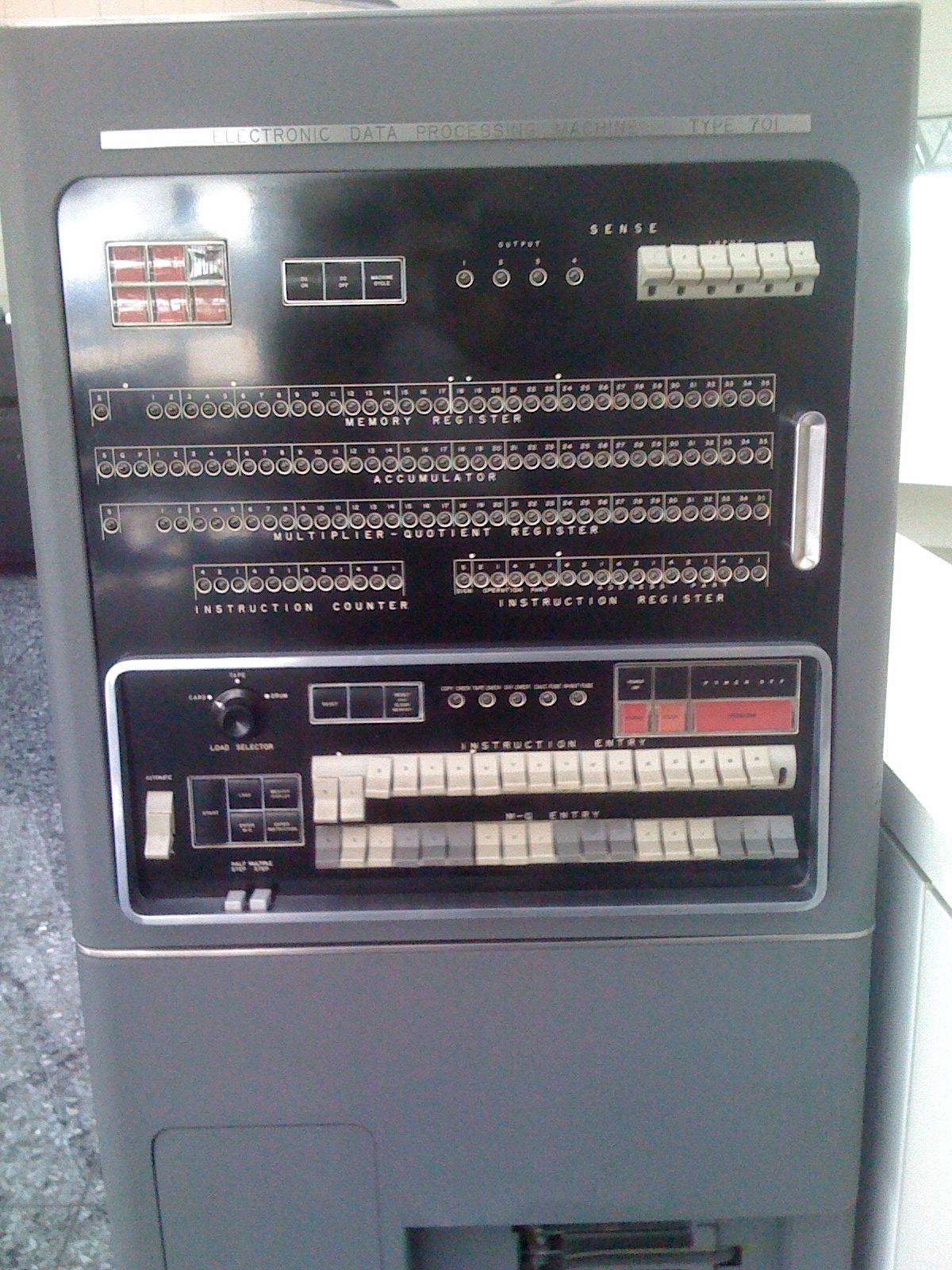
In a simple central processing unit (CPU), the PC is a digital counter (which is the origin of the term "program counter") that may be one of several hardware registers. The instruction cycle[8] begins with a fetch, in which the CPU places the value of the PC on the address bus to send it to the memory. The memory responds by sending the contents of that memory location on the data bus. (This is the stored-program computer model, in which a single memory space contains both executable instructions and ordinary data.[9]) Following the fetch, the CPU proceeds to execution, taking some action based on the memory contents that it obtained. At some point in this cycle, the PC will be modified so that the next instruction executed is a different one (typically, incremented so that the next instruction is the one starting at the memory address immediately following the last memory location of the current instruction).
Like other processor registers, the PC may be a bank of binary latches, each one representing one bit of the value of the PC.[10] The number of bits (the width of the PC) relates to the processor architecture. For instance, a “32-bit” CPU may use 32 bits to be able to address 232 units of memory. On some processors, the width of the program counter instead depends on the addressable memory; for example, some AVR microcontrollers have a PC which wraps around after 12 bits.[11]
If the PC is a binary counter, it may increment when a pulse is applied to its COUNT UP input, or the CPU may compute some other value and load it into the PC by a pulse to its LOAD input.[12]
To identify the current instruction, the PC may be combined with other registers that identify a segment or page. This approach permits a PC with fewer bits by assuming that most memory units of interest are within the current vicinity.
Consequences in machine architecture
[edit]Use of a PC that normally increments assumes that what a computer does is execute a usually linear sequence of instructions. Such a PC is central to the von Neumann architecture. Thus programmers write a sequential control flow even for algorithms that do not have to be sequential. The resulting “von Neumann bottleneck” led to research into parallel computing,[13] including non-von Neumann or dataflow models that did not use a PC; for example, rather than specifying sequential steps, the high-level programmer might specify desired function and the low-level programmer might specify this using combinatory logic.
This research also led to ways to making conventional, PC-based, CPUs run faster, including:
- Pipelining, in which different hardware in the CPU executes different phases of multiple instructions simultaneously.
- The very long instruction word (VLIW) architecture, where a single instruction can achieve multiple effects.
- Techniques to predict out-of-order execution and prepare subsequent instructions for execution outside the regular sequence.
Consequences in high-level programming
[edit]Modern high-level programming languages still follow the sequential-execution model and, indeed, a common way of identifying programming errors is with a “procedure execution” in which the programmer's finger identifies the point of execution as a PC would. The high-level language is essentially the machine language of a virtual machine,[14] too complex to be built as hardware but instead emulated or interpreted by software.
However, new programming models transcend sequential-execution programming:
- When writing a multi-threaded program, the programmer may write each thread as a sequence of instructions without specifying the timing of any instruction relative to instructions in other threads.
- In event-driven programming, the programmer may write sequences of instructions to respond to events without specifying an overall sequence for the program.
- In dataflow programming, the programmer may write each section of a computing pipeline without specifying the timing relative to other sections.
See also
[edit]Notes
[edit]- ^ For modern processors, the concept of "where it is in its sequence" is too simplistic, as instruction-level parallelism and out-of-order execution may occur.
- ^ In a processor where the incrementation precedes the fetch, the PC points to the current instruction being executed. In some processors, the PC points some distance beyond the current instruction; for instance, in the ARM7, the value of PC visible to the programmer points beyond the current instruction and beyond the delay slot.[7]
References
[edit]- ^ a b Hayes, John P. (1978). Computer Architecture and Organization. McGraw-Hill. p. 245. ISBN 0-07-027363-4.
- ^ Mead, Carver; Conway, Lynn (1980). Introduction to VLSI Systems. Reading, USA: Addison-Wesley. ISBN 0-201-04358-0.
- ^ Principles of Operation, Type 701 and Associated Equipment (PDF). IBM. 1953.
- ^ Harry Katzan (1971), Computer Organization and the System/370, Van Nostrand Reinhold Company, New York, USA, LCCCN 72-153191
- ^ Bates, Martin (2011). "Microcontroller Operation". PIC Microcontrollers. Elsevier. pp. 27–44. doi:10.1016/b978-0-08-096911-4.10002-3. ISBN 978-0-08-096911-4.
Program Counter (PC) is a register that keeps track of the program sequence, by storing the address of the instruction currently being executed. It is automatically loaded with zero when the chip is powered up or reset. As each instruction is executed, PC is incremented (increased by one) to point to the next instruction.
- ^ Silberschatz, Abraham; Gagne, Greg; Galvin, Peter B. (April 2018). Operating System Concepts. United States: Wiley. pp. 27, G-29. ISBN 978-1-119-32091-3.
- ^ "ARM Developer Suite, Assembler Guide. Version 1.2". ARM Limited. 2001. Retrieved 2019-10-18.
- ^ John L. Hennessy and David A. Patterson (1990), Computer Architecture: a quantitative approach, Morgan Kaufmann Publishers, Palo Alto, USA, ISBN 1-55860-069-8
- ^ B. Randall (1982), The Origins of Digital Computers, Springer-Verlag, Berlin, D
- ^ C. Gordon Bell and Allen Newell (1971), Computer Structures: Readings and Examples, McGraw-Hill Book Company, New York, USA
- ^ Arnold, Alfred (2020) [1996, 1989]. "E. Predefined Symbols". Macro Assembler AS – User's Manual. V1.42. Translated by Arnold, Alfred; Hilse, Stefan; Kanthak, Stephan; Sellke, Oliver; De Tomasi, Vittorio. p. Table E.3: Predefined Symbols – Part 3. Archived from the original on 2020-02-28. Retrieved 2020-02-28.
3.2.12. WRAPMODE […] AS will assume that the processor's program counter does not have the full length of 16 bits given by the architecture, but instead a length that is exactly sufficient to address the internal ROM. For example, in case of the AT90S8515, this means 12 bits, corresponding to 4 Kwords or 8 Kbytes. This assumption allows relative branches from the ROM's beginning to the end and vice versa which would result in an out-of-branch error when using strict arithmetics. Here, they work because the carry bits resulting from the target address computation are discarded. […] In case of the abovementioned AT90S8515, this option is even necessary because it is the only way to perform a direct jump through the complete address space […]
- ^ Walker, B. S. (1967). Introduction to Computer Engineering. London, UK: University of London Press. ISBN 0-340-06831-0.
- ^ F. B. Chambers, D. A. Duce and G. P. Jones (1984), Distributed Computing, Academic Press, Orlando, USA, ISBN 0-12-167350-2
- ^ Douglas Hofstadter (1980), Gödel, Escher, Bach: an eternal golden braid, Penguin Books, Harmondsworth, UK, ISBN 0-14-005579-7
Program counter
View on GrokipediaFundamentals
Definition and Purpose
The program counter (PC), also known as the instruction address register, is a special-purpose register within a computer's central processing unit (CPU) that holds the memory address of the next instruction to be fetched and executed by the processor.[9] This register is essential for directing the CPU to the precise location in memory where the subsequent machine instruction resides, facilitating the processor's ability to retrieve and process code in a structured manner.[2] The primary purpose of the program counter is to ensure the orderly and sequential execution of instructions by maintaining a pointer to the current position in program memory; after each instruction is fetched, the PC is incremented to point to the next address, thereby preserving the linear flow of program execution unless altered by specific control operations.[10] This mechanism allows the CPU to progress through a program's instructions in the intended order, supporting reliable computation without manual intervention for each step.[11] The PC's role is integral to the instruction fetch-decode-execute cycle, where it initiates the fetch phase by providing the target address.[9] In the context of the von Neumann architecture, the program counter enables the stored-program concept by treating instructions and data within the same unified address space, allowing the CPU to fetch executable code from memory locations just as it accesses operands.[12] This design, proposed in John von Neumann's 1945 report on the EDVAC computer, revolutionized computing by making programs modifiable and stored alongside data, with the PC serving as the dynamic locator for sequential instruction retrieval.[13] For instance, in a basic CPU initialization, the PC is often set to the program's entry point, such as memory address 0x0000, from which it advances incrementally—typically by the fixed size of each instruction—to execute the code in sequence.[14]Basic Operation in Instruction Execution
The program counter (PC) is integral to the CPU's instruction execution cycle, which encompasses the fetch, decode, and execute stages. In the fetch stage, the CPU retrieves the instruction located at the memory address held in the PC and loads it into the instruction register (IR). This process ensures that the processor executes instructions in the intended sequence stored in memory.[15] After fetching the instruction, the PC is automatically incremented by the size of the fetched instruction to prepare for the next one. For instance, in byte-addressable memory with fixed-length 32-bit instructions, the PC advances by 4 bytes; in contrast, byte-addressable systems with variable-length instructions adjust based on the specific instruction size. The decode stage then analyzes the IR contents to identify the operation, operands, and any required resources, while the execute stage performs the computation or memory access as specified, without altering the PC in sequential cases.[16][9][17] PC updates follow specific rules to maintain program flow. For linear execution, the increment occurs post-fetch, as illustrated in this pseudocode:Fetch: IR ← Memory[PC]
PC ← PC + sizeof(instruction)
Fetch: IR ← Memory[PC]
PC ← PC + sizeof(instruction)
Hardware Aspects
Physical Implementation
The program counter (PC) is physically realized as a dedicated register array composed of flip-flops or latches, each bit position storing one element of the instruction address in binary form. This design enables stable storage of the address value until updated on the clock edge, preventing data corruption from asynchronous noise. In modern 64-bit processors, the PC spans 64 flip-flops to handle addresses up to 2^64 bytes, aligning with the architecture's addressing capabilities.[20] Supporting circuitry includes a binary adder for incrementing the PC by the length of the instruction in bytes (e.g., 4 in 32-bit RISC architectures)—during sequential execution, ensuring the next instruction is fetched promptly. Multiplexers route either the incremented value or an external address (e.g., from a branch target) to the PC input, selected by control signals from the instruction decoder. For example, in the Rice BOMB educational processor, the 8-bit PC employs an 8-bit incrementer using an S-R latch for overflow detection and a 16-to-8 multiplexer built from 2-to-1 units to choose between current PC and branch data.[3][21] Clock synchronization governs PC updates, with flip-flops triggered on rising or falling edges to coordinate with the CPU's fetch cycle and maintain timing integrity across the chip. In pipelined designs, the PC generates addresses for concurrent instruction fetches in multiple stages, incorporating buffers to mitigate propagation delays and branch prediction logic to reduce stalls from control hazards.[22] This integration optimizes throughput while managing power by limiting unnecessary increments or loads only when control signals assert. A representative early implementation appears in the MOS Technology 6502 8-bit microprocessor, where the 16-bit PC comprises two cascaded 8-bit registers with internal carry propagation logic to form the full address for its 64 KB space.[23]Integration with CPU Components
The program counter (PC) primarily outputs its value to the memory address bus to facilitate instruction fetching, where it is first loaded into the memory address register (MAR) before being transmitted to main memory via the address bus.[24] This connection ensures that the address of the next instruction is accurately directed to the memory subsystem for retrieval.[25] The PC receives inputs through dedicated load paths, such as from arithmetic logic unit (ALU) computations that generate branch targets or from immediate values in branch instructions, allowing it to update to a new address when control flow changes.[26] It interacts closely with the instruction register (IR), as the fetched instruction from the address specified by the PC is loaded into the IR for subsequent decoding and execution.[27] During subroutine calls and returns, the PC collaborates with the stack pointer (SP); on a call, the current PC value (or PC incremented) is pushed onto the stack using the SP to save the return address, while on return, the saved address is popped from the stack and loaded into the PC.[28][29] In terms of bus protocols, the PC drives the address lines on the shared address bus, often in conjunction with other registers like the MAR, enabling multiplexed access where the bus selects the PC's output for instruction fetch cycles.[30] In pipelined or multi-core systems, bus arbitration mechanisms, such as priority encoders or round-robin schedulers, manage contention when multiple components (including multiple PCs in multi-core setups) attempt to drive the address bus simultaneously, preventing conflicts and ensuring orderly access to shared memory.[31] For example, in RISC architectures like MIPS, the PC feeds directly into the fetch unit, where its value is updated and latched at the end of each clock cycle to maintain synchronization and avoid race conditions between fetch and execution stages.[32][33] This clock-edge alignment ensures that the PC increment—typically adding the instruction length—occurs reliably without overlapping with ongoing fetches.[32]Architectural Consequences
Impact on Machine Design
The width of the program counter (PC) fundamentally constrains the maximum addressable memory space in a processor, as it determines the range of addresses that can be directly referenced for instruction fetch. For instance, a 32-bit PC limits the system to 2^{32} or 4 gigabytes of addressable memory, necessitating additional mechanisms like paging or segmentation for larger systems.[34] This design choice influences overall machine architecture by dictating memory hierarchy depth and bus widths, where narrower PCs reduce hardware overhead but cap scalability, as seen in early 32-bit architectures transitioning to 64-bit for terabyte-scale addressing.[35] In pipelined processors, particularly superscalar and out-of-order designs, PC updates occur dynamically during the fetch stage to sustain high instruction throughput, but control hazards like branches introduce delays that can stall the pipeline. To mitigate this, branch prediction mechanisms forecast the next PC value, allowing speculative execution to overlap fetch with resolution; mispredictions flush the pipeline, incurring penalties proportional to pipeline depth.[36] In out-of-order execution, the PC is managed by the front-end fetch unit, which increments or redirects it based on predicted control flow, decoupling it from execution completion to maximize parallelism while ensuring precise state recovery on exceptions.[37] These adaptations highlight how PC handling shapes pipeline efficiency, with prediction accuracy directly impacting instructions per cycle in modern CPUs.[38] Security features like address space layout randomization (ASLR) leverage the PC's role in address generation to thwart exploits, by randomizing the base addresses of code segments at load time, making it difficult for attackers to predict instruction locations for code injection or return-oriented programming. ASLR perturbs the virtual address space, altering effective PC targets during execution and increasing the entropy required for successful memory corruption attacks.[39] This integration into machine design enhances resilience against buffer overflows but demands compatible hardware support for randomized mapping without performance degradation.[40] Designing wider PCs enables larger address spaces but introduces trade-offs in power consumption and silicon area, as broader registers and address buses require more transistors and wiring, escalating dynamic switching energy and static leakage. For example, extending from 32-bit to 64-bit PC widths increases energy demands in components like the register file due to larger sizes and port configurations, contributing significantly to overall CPU power budgets in high-performance systems. These costs also elevate manufacturing expenses due to greater die area, prompting optimizations like Gray encoding for PC counters to minimize transition activity and power during increments.[41] Thus, architects balance PC width against efficiency constraints, often favoring 64-bit standards for modern scalability despite the overhead.Role in Control Flow and Branching
The program counter (PC) plays a pivotal role in managing non-sequential execution by altering its value to direct the processor to different instructions, thereby implementing control flow mechanisms such as branches and jumps.[42] In unconditional jumps, the PC is directly loaded with a target address specified in the instruction, immediately transferring control without evaluating any conditions.[43] For conditional branches, the PC is updated only if a specified condition—such as a flag in the processor status register being set—is met; otherwise, it proceeds with its normal increment.[44] In such cases, the new PC value is typically computed as the current PC plus a sign-extended offset, enabling relative addressing for efficient code organization: \text{new_PC} = \text{current_PC} + \text{sign-extended_offset} This formula allows branches to reference nearby instructions without absolute addresses.[45] Subroutine calls extend this by first pushing the current PC (return address) onto the stack before loading the target subroutine address into the PC, facilitating a return via stack pop.[46] Interrupt handling further demonstrates the PC's role in asynchronous control transfers, where external events suspend normal execution. Upon detecting an interrupt, the processor automatically saves the current PC (along with status information) to the stack or a designated memory area, then loads a new PC value from an interrupt vector table that points to the handler routine's entry point.[47] After the handler completes its task, the saved PC is restored from the stack, resuming the interrupted program from the precise point of suspension.[48] This mechanism ensures reliable context switching without data loss, with vector tables serving as a fixed mapping of interrupt types to handler addresses.[43] To mitigate performance penalties from frequent branches and interrupts, modern processors employ prediction mechanisms centered on the PC. The branch target buffer (BTB) is a cache that associates recent PC values of branch instructions with their predicted target addresses and outcomes (taken or not taken), allowing the fetch unit to speculatively load instructions from the anticipated next PC before resolution.[49] If a misprediction occurs—such as an incorrect target guess—the pipeline flushes incorrect instructions and corrects the PC, incurring a penalty proportional to pipeline depth; the BTB reduces these by caching historical patterns, improving overall throughput in branch-heavy code.[50] In the x86 architecture, the JMP instruction exemplifies direct PC manipulation for unconditional jumps, loading the specified target address directly into the EIP (extended instruction pointer, the 32-bit PC equivalent) without saving return information, thus enabling arbitrary control transfers.[51] Relative variants of JMP or conditional jumps like JE (jump if equal) apply the offset formula to the current EIP, supporting compact encoding for loops and decisions common in compiled code.[52]Programming Implications
Representation in Low-Level Code
In low-level assembly languages, the program counter (PC) is manipulated primarily through dedicated branch and jump instructions that alter the flow of execution by updating the PC to a new address. In x86 architecture, instructions such as JMP (unconditional jump) directly load a specified address into the instruction pointer (EIP in 32-bit mode or RIP in 64-bit mode), while CALL pushes the current PC onto the stack and sets the PC to the target subroutine address for function invocation.[51] Similarly, in ARM architecture, the B (branch) instruction unconditionally sets the PC to a target address, and BL (branch with link) performs the same while saving the return address in the link register (R14).[53] These operations enable explicit control over the PC without intermediate register loads in most cases, though indirect manipulation occurs when addresses are computed in general-purpose registers before branching.[54] PC-relative addressing modes further integrate the PC into low-level code by calculating effective addresses as offsets from the current PC value, facilitating position-independent code that remains functional across memory relocations. In x86-64, RIP-relative addressing encodes operands as signed offsets added to the RIP, commonly used in instructions like MOV or LEA for accessing global data without absolute addresses.[51] ARM supports PC-relative addressing in load/store instructions such as LDR (load register), where the offset is added to the PC (R15) to fetch data from a nearby memory location, typically within ±4KB in Thumb state or larger ranges in AArch64 via ADRP/ADD combinations.[55] This mode is essential for compact, relocatable binaries, as the assembler resolves labels to offsets during linking without embedding fixed addresses.[56] During debugging, tools like the GNU Debugger (GDB) provide visibility into the PC's value, allowing developers to inspect and trace execution. In GDB, the commandprint $pc displays the current PC address in the selected frame, while x/i $pc disassembles the instruction at that location, aiding in step-by-step analysis of control flow.[57] This feature is particularly useful for verifying branch targets or diagnosing infinite loops where the PC repeatedly cycles through addresses.
A representative example of PC manipulation appears in assembly loops, where conditional jumps implicitly update the PC based on flags set by comparison instructions. Consider this simplified x86-64 loop that decrements a register until zero:
loop_start:
cmp rax, 0 ; Compare RAX to 0, sets flags
je loop_end ; Jump if equal (ZF=1), updates RIP to end
sub rax, 1 ; Decrement RAX
jmp loop_start ; Unconditional jump back, sets RIP to start
loop_end:
loop_start:
cmp rax, 0 ; Compare RAX to 0, sets flags
je loop_end ; Jump if equal (ZF=1), updates RIP to end
sub rax, 1 ; Decrement RAX
jmp loop_start ; Unconditional jump back, sets RIP to start
loop_end:
loop_start:
cmp r0, #0 ; Compare R0 to 0
beq loop_end ; Branch if equal, updates PC to end
sub r0, r0, #1 ; Decrement R0
b loop_start ; Branch back, PC-relative offset to start
loop_end:
loop_start:
cmp r0, #0 ; Compare R0 to 0
beq loop_end ; Branch if equal, updates PC to end
sub r0, r0, #1 ; Decrement R0
b loop_start ; Branch back, PC-relative offset to start
loop_end:
