

Community hub
Recent from talks
Contribute something
Nothing was collected or created yet.
Loudspeaker
View on Wikipedia
This article needs additional citations for verification. (April 2024) |

- Mid-range driver
- Tweeter
- Woofers
A loudspeaker (commonly referred to as a speaker or, more fully, a speaker system) is a combination of one or more speaker drivers, an enclosure, and electrical connections (possibly including a crossover network). The speaker driver is an electroacoustic transducer[1]: 597 that converts an electrical audio signal into a corresponding sound.[2]
The driver is a linear motor connected to a diaphragm, which transmits the motor's movement to produce sound by moving air. An audio signal, typically originating from a microphone, recording, or radio broadcast, is electronically amplified to a power level sufficient to drive the motor, reproducing the sound corresponding to the original unamplified signal. This process functions as the inverse of a microphone. In fact, the dynamic speaker driver—the most common type—shares the same basic configuration as a dynamic microphone, which operates in reverse as a generator.
The dynamic speaker was invented in 1925 by Edward W. Kellogg and Chester W. Rice. When the electrical current from an audio signal passes through its voice coil—a coil of wire capable of moving axially in a cylindrical gap containing a concentrated magnetic field produced by a permanent magnet—the coil is forced to move rapidly back and forth due to Faraday's law of induction; this attaches to a diaphragm or speaker cone (as it is usually conically shaped for sturdiness) in contact with air, thus creating sound waves. In addition to dynamic speakers, several other technologies are possible for creating sound from an electrical signal, a few of which are in commercial use.
For a speaker to efficiently produce sound, especially at lower frequencies, the speaker driver must be baffled so that the sound emanating from its rear does not cancel out the (intended) sound from the front; this generally takes the form of a speaker enclosure or speaker cabinet, an often rectangular box made of wood, but sometimes metal or plastic. The enclosure's design plays an important acoustic role thus determining the resulting sound quality. Most high fidelity speaker systems (picture at right) include two or more sorts of speaker drivers, each specialized in one part of the audible frequency range. The smaller drivers capable of reproducing the highest audio frequencies are called tweeters, those for middle frequencies are called mid-range drivers and those for low frequencies are called woofers. In a two-way or three-way speaker system (one with drivers covering two or three different frequency ranges) there is a small amount of passive electronics called a crossover network which helps direct components of the electronic signal to the speaker drivers best capable of reproducing those frequencies. In a powered speaker system, the power amplifier actually feeding the speaker drivers is built into the enclosure itself; these have become more and more common, especially as computer and Bluetooth speakers.
Smaller speakers are found in devices such as radios, televisions, portable audio players, personal computers (computer speakers), headphones, and earphones. Larger, louder speaker systems are used for home hi-fi systems (stereos), electronic musical instruments, sound reinforcement in theaters and concert halls, and in public address systems.
Terminology
[edit]The term loudspeaker may refer to individual transducers (also known as drivers) or to complete speaker systems consisting of an enclosure and one or more drivers.
To adequately and accurately reproduce a wide range of frequencies with even coverage, most loudspeaker systems employ more than one driver, particularly for higher sound pressure level (SPL) or maximum accuracy. Individual drivers are used to reproduce different frequency ranges. The drivers are named subwoofers (for very low frequencies); woofers (low frequencies); mid-range speakers (middle frequencies); tweeters (high frequencies); and sometimes supertweeters, for the highest audible frequencies and beyond. The terms for different speaker drivers differ, depending on the application. In two-way systems there is no mid-range driver, so the task of reproducing the mid-range sounds is divided between the woofer and tweeter. When multiple drivers are used in a system, a filter network, called an audio crossover, separates the incoming signal into different frequency ranges and routes them to the appropriate driver. A loudspeaker system with n separate frequency bands is described as n-way speakers: a two-way system will have a woofer and a tweeter; a three-way system employs a woofer, a mid-range, and a tweeter. Loudspeaker drivers of the type pictured are termed dynamic (short for electrodynamic) to distinguish them from other sorts including moving iron speakers, and speakers using piezoelectric or electrostatic systems.
History
[edit]Johann Philipp Reis installed an electric loudspeaker in his telephone in 1861; it was capable of reproducing clear tones, but later revisions could also reproduce muffled speech.[3] Alexander Graham Bell patented his first electric loudspeaker (a moving iron type capable of reproducing intelligible speech) as part of his telephone in 1876, which was followed in 1877 by an improved version from Ernst Siemens. During this time, Thomas Edison was issued a British patent for a system using compressed air as an amplifying mechanism for his early cylinder phonographs, but he ultimately settled for the familiar metal horn driven by a membrane attached to the stylus. In 1898, Horace Short patented a design for a loudspeaker driven by compressed air; he then sold the rights to Charles Parsons, who was issued several additional British patents before 1910. A few companies, including the Victor Talking Machine Company and Pathé, produced record players using compressed-air loudspeakers. Compressed-air designs are significantly limited by their poor sound quality and their inability to reproduce sound at low volume. Variants of the design were used for public address applications, and more recently, other variations have been used to test space-equipment resistance to the very loud sound and vibration levels that the launching of rockets produces.[4]
Moving-coil
[edit]The first experimental moving-coil (also called dynamic) loudspeaker was invented by Oliver Lodge in 1898.[5] The first practical moving-coil loudspeakers were manufactured by Danish engineer Peter L. Jensen and Edwin Pridham in 1915, in Napa, California.[6] Like previous loudspeakers these used horns to amplify the sound produced by a small diaphragm. Jensen was denied patents. Being unsuccessful in selling their product to telephone companies, in 1915 they changed their target market to radios and public address systems, and named their product Magnavox. Jensen was, for years after the invention of the loudspeaker, a part owner of The Magnavox Company.[7]


The moving-coil principle commonly used today in speakers was patented in 1925 by Edward W. Kellogg and Chester W. Rice. The key difference between previous attempts and the patent by Rice and Kellogg is the adjustment of mechanical parameters to provide a reasonably flat frequency response.[8]
These first loudspeakers used electromagnets, because large, powerful permanent magnets were generally not available at a reasonable price. The coil of an electromagnet, called a field coil, was energized by a current through a second pair of connections to the driver. This winding usually served a dual role, acting also as a choke coil, filtering the power supply of the amplifier that the loudspeaker was connected to.[9] AC ripple in the current was attenuated by the action of passing through the choke coil. However, AC line frequencies tended to modulate the audio signal going to the voice coil and added to the audible hum. In 1930 Jensen introduced the first commercial fixed-magnet loudspeaker; however, the large, heavy iron magnets of the day were impractical and field-coil speakers remained predominant until the widespread availability of lightweight alnico magnets after World War II.
First loudspeaker systems
[edit]In the 1930s, loudspeaker manufacturers began to combine two and three drivers or sets of drivers each optimized for a different frequency range in order to improve frequency response and increase sound pressure level.[10] In 1937, the first film industry-standard loudspeaker system, "The Shearer Horn System for Theatres",[11] a two-way system, was introduced by Metro-Goldwyn-Mayer. It used four 15" low-frequency drivers, a crossover network set for 375 Hz, and a single multi-cellular horn with two compression drivers providing the high frequencies. John Kenneth Hilliard, James Bullough Lansing, and Douglas Shearer all played roles in creating the system. At the 1939 New York World's Fair, a very large two-way public address system was mounted on a tower at Flushing Meadows. The eight 27" low-frequency drivers were designed by Rudy Bozak in his role as chief engineer for Cinaudagraph. High-frequency drivers were likely made by Western Electric.[12]
Altec Lansing introduced the 604, which became their most famous coaxial Duplex driver, in 1943. It incorporated a high-frequency horn that sent sound through a hole in the pole piece of a 15-inch woofer for near-point-source performance.[13] Altec's "Voice of the Theatre" loudspeaker system was first sold in 1945, offering better coherence and clarity at the high output levels necessary in movie theaters.[14] The Academy of Motion Picture Arts and Sciences immediately began testing its sonic characteristics; they made it the film house industry standard in 1955.[15]
In 1954, Edgar Villchur developed the acoustic suspension principle of loudspeaker design. This allowed for better bass response than previously obtainable from drivers mounted in larger cabinets.[16] He and his partner Henry Kloss formed the Acoustic Research company to manufacture and market speaker systems using this principle.[17] Subsequently, continuous developments in enclosure design and materials led to significant audible improvements.[18]
The most notable improvements to date in modern dynamic drivers, and the loudspeakers that employ them, are improvements in cone materials, the introduction of higher-temperature adhesives, improved permanent magnet materials, improved measurement techniques, computer-aided design, and finite element analysis. At low frequencies, Thiele/Small parameters electrical network theory has been used to optimize bass driver and enclosure synergy since the early 1970s.[19]
Driver design: dynamic loudspeakers
[edit]
- Magnet
- Voice coil
- Suspension
- Diaphragm

- Magnet
- Cooler (sometimes present)
- Voice coil
- Suspension
- Diaphragm

- Magnet
- Voice coil
- Diaphragm
- Suspension

The most common type of driver, commonly called a dynamic loudspeaker, uses a lightweight diaphragm, or cone, connected to a rigid basket, or frame, via a flexible suspension, commonly called a spider, that constrains a voice coil to move axially through a cylindrical magnetic gap. A protective dust cap glued in the cone's center prevents dust, most importantly ferromagnetic debris, from entering the gap.
When an electrical signal is applied to the voice coil, a magnetic field is created by the electric current in the voice coil, making it a variable electromagnet. The coil and the driver's magnetic system interact in a manner similar to a solenoid, generating a mechanical force that moves the coil (and thus, the attached cone). Application of alternating current moves the cone back and forth, accelerating and reproducing sound under the control of the applied electrical signal coming from the amplifier.
The following is a description of the individual components of this type of loudspeaker.
Diaphragm
[edit]The diaphragm is usually manufactured with a cone- or dome-shaped profile. A variety of different materials may be used, but the most common are paper, plastic, and metal. The ideal material is rigid, to prevent uncontrolled cone motions, has low mass to minimize starting force requirements and energy storage issues and is well damped to reduce vibrations continuing after the signal has stopped with little or no audible ringing due to its resonance frequency as determined by its usage. In practice, all three of these criteria cannot be met simultaneously using existing materials; thus, driver design involves trade-offs. For example, paper is light and typically well-damped, but is not stiff; metal may be stiff and light, but it usually has poor damping; plastic can be light, but typically, the stiffer it is made, the poorer the damping. As a result, many cones are made of some sort of composite material. For example, a cone might be made of cellulose paper, into which some carbon fiber, Kevlar, glass, hemp or bamboo fibers have been added; or it might use a honeycomb sandwich construction; or a coating might be applied to it so as to provide additional stiffening or damping.
Basket
[edit]The chassis, frame, or basket, is designed to be rigid, preventing deformation that could change critical alignments with the magnet gap, perhaps allowing the voice coil to rub against the magnet around the gap. Chassis are typically cast from aluminum alloy, in heavier magnet-structure speakers; or stamped from thin sheet steel in lighter-structure drivers.[20] Other materials such as molded plastic and damped plastic compound baskets are becoming common, especially for inexpensive, low-mass drivers. A metallic chassis can play an important role in conducting heat away from the voice coil; heating during operation changes resistance, causes physical dimensional changes, and if extreme, broils the varnish on the voice coil; it may even demagnetize permanent magnets.
Suspension
[edit]The suspension system keeps the coil centered in the gap and provides a restoring (centering) force that returns the cone to a neutral position after moving. A typical suspension system consists of two parts: the spider, which connects the diaphragm or voice coil to the lower frame and provides the majority of the restoring force, and the surround, which helps center the coil/cone assembly and allows free pistonic motion aligned with the magnetic gap. The spider is usually made of a corrugated fabric disk, impregnated with a stiffening resin. The name comes from the shape of early suspensions, which were two concentric rings of Bakelite material, joined by six or eight curved legs. Variations of this topology included the addition of a felt disc to provide a barrier to particles that might otherwise cause the voice coil to rub.
The cone surround can be rubber or polyester foam, treated paper or a ring of corrugated, resin-coated fabric; it is attached to both the outer cone circumference and to the upper frame. These diverse surround materials, their shape and treatment can dramatically affect the acoustic output of a driver; each implementation has advantages and disadvantages. Polyester foam, for example, is lightweight and economical, though usually leaks air to some degree and is degraded by time, exposure to ozone, UV light, humidity and elevated temperatures, limiting useful life before failure.
Voice coil
[edit]The wire in a voice coil is usually made of copper, though aluminum—and, rarely, silver—may be used. The advantage of aluminum is its light weight, which reduces the moving mass compared to copper. This raises the resonant frequency of the speaker and increases its efficiency. A disadvantage of aluminum is that it is not easily soldered, and so connections must be robustly crimped together and sealed. Voice-coil wire cross sections can be circular, rectangular, or hexagonal, giving varying amounts of wire volume coverage in the magnetic gap space. The coil is oriented co-axially inside the gap; it moves back and forth within a small circular volume (a hole, slot, or groove) in the magnetic structure. The gap establishes a concentrated magnetic field between the two poles of a permanent magnet; the outside ring of the gap is one pole, and the center post (called the pole piece) is the other. The pole piece and backplate are often made as a single piece, called the poleplate or yoke.
Magnet
[edit]The size and type of magnet and details of the magnetic circuit differ, depending on design goals. For instance, the shape of the pole piece affects the magnetic interaction between the voice coil and the magnetic field, and is sometimes used to modify a driver's behavior. A shorting ring, or Faraday loop, may be included as a thin copper cap fitted over the pole tip or as a heavy ring situated within the magnet-pole cavity. The benefits of this complication is reduced impedance at high frequencies, providing extended treble output, reduced harmonic distortion, and a reduction in the inductance modulation that typically accompanies large voice coil excursions. On the other hand, the copper cap requires a wider voice-coil gap, with increased magnetic reluctance; this reduces available flux, requiring a larger magnet for equivalent performance.
Electromagnets were often used in musical instrument amplifiers cabinets well into the 1950s; there were economic savings in those using tube amplifiers as the field coil could, and usually did, do double duty as a power supply choke. Very few manufacturers still produce electrodynamic loudspeakers with electrically powered field coils, as was common in the earliest designs.
Alnico, an alloy of aluminum, nickel, and cobalt became popular after WWII, since it dispensed with the problems of field-coil drivers. Alnico was commonly used until the 1960s, despite the problem of alnico magnets being partially demagnetized.[21] In the 1960s, most driver manufacturers switched from alnico to ferrite magnets, which are made from a mix of ceramic clay and fine particles of barium or strontium ferrite. Although the energy per kilogram of these ceramic magnets is lower than alnico, it is substantially less expensive, allowing designers to use larger yet more economical magnets to achieve a given performance. Due to increases in transportation costs and a desire for smaller, lighter devices, there is a trend toward the use of more compact rare-earth magnets made from materials such as neodymium and samarium cobalt.[22]Speaker systems
[edit]Speaker system design involves subjective perceptions of timbre and sound quality, measurements and experiments.[23][24][25] Adjusting a design to improve performance is done using a combination of magnetic, acoustic, mechanical, electrical, and materials science theory, and tracked with high-precision measurements and the observations of experienced listeners. A few of the issues speaker and driver designers must confront are distortion, acoustic lobing, phase effects, off-axis response, and crossover artifacts. Designers can use an anechoic chamber to ensure the speaker can be measured independently of room effects, or any of several electronic techniques that, to some extent, substitute for such chambers. Some developers eschew anechoic chambers in favor of specific standardized room setups intended to simulate real-life listening conditions.

Individual electrodynamic drivers provide their best performance within a limited frequency range. Multiple drivers (e.g. subwoofers, woofers, mid-range drivers, and tweeters) are generally combined into a complete loudspeaker system to provide performance beyond that constraint. The three most commonly used sound radiation systems are the cone, dome and horn-type drivers.
Full-range drivers
[edit]A full- or wide-range driver is a speaker driver designed to be used alone to reproduce an audio channel without the help of other drivers and therefore must cover the audio frequency range required by the application. These drivers are small, typically 3 to 8 inches (7.6 to 20.3 cm) in diameter to permit reasonable high-frequency response, and carefully designed to give low-distortion output at low frequencies, though with reduced maximum output level. Full-range drivers are found, for instance, in public address systems, in televisions, small radios, intercoms, and some computer speakers.
In hi-fi speaker systems, the use of wide-range drivers can avoid undesirable interactions between multiple drivers caused by non-coincident driver location or crossover network issues but also may limit frequency response and output abilities (most especially at low frequencies). Hi-fi speaker systems built with wide-range drivers may require large, elaborate or, expensive enclosures to approach optimum performance.
_full-range_drive_unit_loudspeaker,_using_a_whizzer_cone.jpg)
Full-range drivers often employ an additional cone called a whizzer: a small, light cone attached to the joint between the voice coil and the primary cone. The whizzer cone extends the high-frequency response of the driver and broadens its high-frequency directivity, which would otherwise be greatly narrowed due to the outer diameter cone material failing to keep up with the central voice coil at higher frequencies. The main cone in a whizzer design is manufactured so as to flex more in the outer diameter than in the center. The result is that the main cone delivers low frequencies and the whizzer cone contributes most of the higher frequencies. Since the whizzer cone is smaller than the main diaphragm, output dispersion at high frequencies is improved relative to an equivalent single larger diaphragm.
Limited-range drivers, also used alone, are typically found in computers, toys, and clock radios. These drivers are less elaborate and less expensive than wide-range drivers, and they may be severely compromised to fit into very small mounting locations. In these applications, sound quality is a low priority.
Subwoofer
[edit]A subwoofer is a woofer driver used only for the lowest-pitched part of the audio spectrum: typically below 200 Hz for consumer systems,[26] below 100 Hz for professional live sound,[27] and below 80 Hz in THX-approved systems.[28] Because the intended range of frequencies is limited, subwoofer system design is usually simpler in many respects than for conventional loudspeakers, often consisting of a single driver enclosed in a suitable enclosure. Since sound in this frequency range can easily bend around corners by diffraction, the speaker aperture does not have to face the audience, and subwoofers can be mounted in the bottom of the enclosure, facing the floor. This is eased by the limitations of human hearing at low frequencies; Such sounds cannot be located in space, due to their large wavelengths compared to higher frequencies which produce differential effects in the ears due to shadowing by the head, and diffraction around it, both of which we rely upon for localization clues.
To accurately reproduce very low bass notes, subwoofer systems must be solidly constructed and properly braced to avoid unwanted sounds from cabinet vibrations. As a result, good subwoofers are typically quite heavy. Many subwoofer systems include integrated power amplifiers and electronic subsonic-filters, with additional controls relevant to low-frequency reproduction (e.g. a crossover knob and a phase switch). These variants are known as active or powered subwoofers.[29] In contrast, passive subwoofers require external amplification.
In typical installations, subwoofers are physically separated from the rest of the speaker cabinets. Because of propagation delay and positioning, their output may be out of phase with the rest of the sound. Consequently, a subwoofer's power amp often has a phase-delay adjustment which may be used improve performance of the system as a whole. Subwoofers are widely used in large concert and mid-sized venue sound reinforcement systems. Subwoofer cabinets are often built with a bass reflex port, a design feature which if properly engineered improves bass performance and increases efficiency.
Woofer
[edit]A woofer is a driver that reproduces low frequencies. The driver works with the characteristics of the speaker enclosure to produce suitable low frequencies. Some loudspeaker systems use a woofer for the lowest frequencies, sometimes well enough that a subwoofer is not needed. Additionally, some loudspeakers use the woofer to handle middle frequencies, eliminating the mid-range driver.
Mid-range driver
[edit]A mid-range speaker is a loudspeaker driver that reproduces a band of frequencies generally between 1–6 kHz, otherwise known as the mid frequencies (between the woofer and tweeter). Mid-range driver diaphragms can be made of paper or composite materials and can be direct radiation drivers (rather like smaller woofers) or they can be compression drivers (rather like some tweeter designs). If the mid-range driver is a direct radiator, it can be mounted on the front baffle of a loudspeaker enclosure, or, if a compression driver, mounted at the throat of a horn for added output level and control of radiation pattern.
Tweeter
[edit]
A tweeter is a high-frequency driver that reproduces the highest frequencies in a speaker system. A major problem in tweeter design is achieving wide angular sound coverage (off-axis response), since high-frequency sound tends to leave the speaker in narrow beams. Soft-dome tweeters are widely found in home stereo systems, and horn-loaded compression drivers are common in professional sound reinforcement. Ribbon tweeters have gained popularity as the output power of some designs has been increased to levels useful for professional sound reinforcement, and their output pattern is wide in the horizontal plane, a pattern that has convenient applications in concert sound.[30]
Coaxial drivers
[edit]A coaxial driver is a loudspeaker driver with two or more combined concentric drivers. Coaxial drivers have been produced by Altec, Tannoy, Pioneer, KEF, SEAS, B&C Speakers, BMS, Cabasse and Genelec.[31]
System design
[edit]
Crossover
[edit]

Used in multi-driver speaker systems, the crossover is an assembly of filters that separate the input signal into different frequency bands according to the requirements of each driver. Hence the drivers receive power only in the sound frequency range they were designed for, thereby reducing distortion in the drivers and interference between them. Crossovers can be passive or active.
A passive crossover is an electronic circuit that uses a combination of one or more resistors, inductors and capacitors. These components are combined to form a filter network and are most often placed between the full frequency-range power amplifier and the loudspeaker drivers to divide the amplifier's signal into the necessary frequency bands before being delivered to the individual drivers. Passive crossover circuits need no external power beyond the audio signal itself, but have some disadvantages: they may require larger inductors and capacitors due to power handling requirements. Unlike active crossovers which include a built-in amplifier, passive crossovers have an inherent attenuation within the passband, typically leading to a reduction in damping factor before the voice coil.[citation needed]
An active crossover is an electronic filter circuit that divides the signal into individual frequency bands before power amplification, thus requiring at least one power amplifier for each band.[citation needed] Passive filtering may also be used in this way before power amplification, but it is an uncommon solution, being less flexible than active filtering. Any technique that uses crossover filtering followed by amplification is commonly known as bi-amping, tri-amping, quad-amping, and so on, depending on the minimum number of amplifier channels.[32]
Some loudspeaker designs use a combination of passive and active crossover filtering, such as a passive crossover between the mid- and high-frequency drivers and an active crossover for the low-frequency driver.[33][34]
Passive crossovers are commonly installed inside speaker boxes and are by far the most common type of crossover for home and low-power use. In car audio systems, passive crossovers may be in a separate box, necessary to accommodate the size of the components used. Passive crossovers may be simple for low-order filtering, or complex to allow steep slopes such as 18 or 24 dB per octave. Passive crossovers can also be designed to compensate for undesired characteristics of driver, horn, or enclosure resonances, and can be tricky to implement, due to component interaction. Passive crossovers, like the driver units that they feed, have power handling limits, have insertion losses, and change the load seen by the amplifier. The changes are matters of concern for many in the hi-fi world.[citation needed] When high output levels are required, active crossovers may be preferable. Active crossovers may be simple circuits that emulate the response of a passive network or may be more complex, allowing extensive audio adjustments. Some active crossovers, usually digital loudspeaker management systems, may include electronics and controls for precise alignment of phase and time between frequency bands, equalization, dynamic range compression and limiting.[citation needed]
Enclosures
[edit]
Most loudspeaker systems consist of drivers mounted in an enclosure, or cabinet. The role of the enclosure is to prevent sound waves emanating from the back of a driver from interfering destructively with those from the front. The sound waves emitted from the back are 180° out of phase with those emitted forward, so without an enclosure they typically cause cancellations which significantly degrade the level and quality of sound at low frequencies.
The simplest driver mount is a flat panel (baffle) with the drivers mounted in holes in it. However, in this approach, sound frequencies with a wavelength longer than the baffle dimensions are canceled out because the antiphase radiation from the rear of the cone interferes with the radiation from the front. With an infinitely large panel, this interference could be entirely prevented. A sufficiently large sealed box can approach this behavior.[35][36]
Since panels of infinite dimensions are impossible, most enclosures function by containing the rear radiation from the moving diaphragm. A sealed enclosure prevents transmission of the sound emitted from the rear of the loudspeaker by confining the sound in a rigid and airtight box. Techniques used to reduce the transmission of sound through the walls of the cabinet include thicker cabinet walls, internal bracing and lossy wall material.
However, a rigid enclosure reflects sound internally, which can then be transmitted back through the loudspeaker diaphragm—again resulting in degradation of sound quality. This can be reduced by internal absorption using absorptive materials such as glass wool, wool, or synthetic fiber batting, within the enclosure. The internal shape of the enclosure can also be designed to reduce this by reflecting sounds away from the loudspeaker diaphragm, where they may then be absorbed.
Other enclosure types alter the rear sound radiation so it can add constructively to the output from the front of the cone. Designs that do this (including bass reflex, passive radiator, transmission line, etc.) are often used to extend the effective low-frequency response and increase the low-frequency output of the driver.
To make the transition between drivers as seamless as possible, system designers have attempted to time align the drivers by moving one or more driver mounting locations forward or back so that the acoustic center of each driver is in the same vertical plane. This may also involve tilting the driver back, providing a separate enclosure mounting for each driver, or using electronic techniques to achieve the same effect. These attempts have resulted in some unusual cabinet designs.
The speaker mounting scheme (including cabinets) can also cause diffraction, resulting in peaks and dips in the frequency response. The problem is usually greatest at higher frequencies, where wavelengths are similar to, or smaller than, cabinet dimensions.
Horn loudspeakers
[edit]
.png)
Horn loudspeakers are the oldest form of loudspeaker system. The use of horns as voice-amplifying megaphones dates at least to the 17th century,[37] and horns were used in mechanical gramophones as early as 1877. Horn loudspeakers use a shaped waveguide in front of or behind the driver to increase the directivity of the loudspeaker and to transform a small diameter, high-pressure condition at the driver cone surface to a large diameter, low-pressure condition at the mouth of the horn. This improves the acoustic—electro/mechanical impedance match between the driver and ambient air, increasing efficiency, and focusing the sound over a narrower area.
The size of the throat, mouth, the length of the horn, as well as the area expansion rate along it must be carefully chosen to match the driver to properly provide this transforming function over a range of frequencies.[a] The length and cross-sectional mouth area required to create a bass or sub-bass horn dictates a horn many feet long. Folded horns can reduce the total size, but compel designers to make compromises and accept increased cost and construction complications. Some horn designs not only fold the low-frequency horn but use the walls in a room corner as an extension of the horn mouth. In the late 1940s, horns whose mouths took up much of a room wall were not unknown among hi-fi fans. Room-sized installations became much less acceptable when two or more were required.
A horn-loaded speaker can have a sensitivity as high as 110 dBSPL at 2.83 volts (1 watt at 8 ohms) at 1 meter. This is a hundredfold increase in output compared to a speaker rated at 90 dB sensitivity (given the aforementioned specifications) and is invaluable in applications where high sound levels are required or amplifier power is limited.
Transmission line loudspeaker
[edit]A transmission line loudspeaker is a loudspeaker enclosure design that uses an acoustic transmission line within the cabinet, compared to the simpler enclosure-based designs. Instead of reverberating in a fairly simple damped enclosure, sound from the back of the bass speaker is directed into a long (generally folded) damped pathway within the speaker enclosure, which allows greater control and efficient use of speaker energy.
Wiring connections
[edit]


Most home hi-fi loudspeakers use two wiring points to connect to the source of the signal (for example, to the audio amplifier or receiver). To accept the wire connection, the loudspeaker enclosure may have binding posts, spring clips, or a panel-mount jack. If the wires for a pair of speakers are not connected with respect to the proper electrical polarity,[b] the loudspeakers are said to be out of phase or more properly out of polarity.[38][39] Given identical signals, motion in the cone of an out of polarity loudspeaker is in the opposite direction of the others. This typically causes monophonic material in a stereo recording to be canceled out, reduced in level, and made more difficult to localize, all due to destructive interference of the sound waves. The cancellation effect is most noticeable at frequencies where the loudspeakers are separated by a quarter wavelength or less; low frequencies are affected the most. This type of miswiring error does not damage speakers, but is not optimal for listening.[40][41]
With sound reinforcement system, PA system and instrument amplifier speaker enclosures, cables and some type of jack or connector are typically used. Lower- and mid-priced sound system and instrument speaker cabinets often use 1/4" jacks. Higher-priced and higher-powered sound system cabinets and instrument speaker cabinets often use Speakon connectors. Speakon connectors are considered to be safer for high-wattage amplifiers, because the connector is designed so that human users cannot touch the connectors.
Wireless speakers
[edit]
Wireless speakers are similar to wired powered speakers, but they receive audio signals using radio frequency (RF) waves rather than over audio cables. There is an amplifier integrated in the speaker's cabinet because the RF waves alone are not enough to drive the speaker. Wireless speakers still need power, so require a nearby AC power outlet, or onboard batteries. Only the wire for the audio is eliminated.
Specifications
[edit]
Speaker specifications generally include:
- Speaker or driver type (individual units only) – full-range, woofer, tweeter, or mid-range.
- Size of individual drivers. For cone drivers, the quoted size is generally the outside diameter of the basket.[42] However, it may less commonly also be the diameter of the cone surround, measured apex to apex, or the distance from the center of one mounting hole to its opposite. Voice-coil diameter may also be specified. If the loudspeaker has a compression horn driver, the diameter of the horn throat may be given.
- Rated power – power, and peak power a loudspeaker can handle. A driver may be damaged at much less than its rated power if driven past its mechanical limits at lower frequencies.[citation needed] In some jurisdictions, power handling has a legal meaning allowing comparisons between loudspeakers under consideration. Elsewhere, the variety of meanings for power handling capacity can be quite confusing.
- Impedance – typically 4 Ω (ohms), 8 Ω, etc.[43]
- Baffle or enclosure type (enclosed systems only) – Sealed, bass reflex, etc.
- Number of drivers (complete speaker systems only) – two-way, three-way, etc.
- Class of loudspeaker:[44]
- Class 1: maximum SPL 110–119 dB, the type of loudspeaker used for reproducing a person speaking in a small space or for background music; mainly used as fill speakers for Class 2 or Class 3 speakers; typically small 4" or 5" woofers and dome tweeters
- Class 2: maximum SPL 120–129 dB, the type of medium-power–capable loudspeaker used for reinforcement in small to medium spaces or as fill speakers for Class 3 or Class 4 speakers; typically 5" to 8" woofers and dome tweeters
- Class 3: maximum SPL 130–139 dB, high-power–capable loudspeakers used in main systems in small to medium spaces; also used as fill speakers for class 4 speakers; typically 6.5" to 12" woofers and 2" or 3" compression drivers for high frequencies
- Class 4: maximum SPL 140 dB and higher, very-high-power–capable loudspeakers used as mains in medium to large spaces (or for fill speakers for these medium to large spaces); 10" to 15" woofers and 3" compression drivers
and optionally:
- Crossover frequency(ies) (multi-driver systems only) – The nominal frequency boundaries of the division between drivers.
- Frequency response – The measured, or specified, output over a specified range of frequencies for a constant input level varied across those frequencies. It sometimes includes a variance limit, such as within "± 2.5 dB."
- Thiele/Small parameters (individual drivers only) – these include the driver's Fs (resonance frequency), Qts (a driver's Q; more or less, its damping factor at resonant frequency), Vas (the equivalent air compliance volume of the driver), etc.
- Sensitivity – The sound pressure level produced by a loudspeaker in a non-reverberant environment, often specified in SPL measured at 1 meter with an input of 1 watt (2.83 volts RMS into 8 Ω), typically at one or more specified frequencies. Manufacturers often use this rating in marketing material.
- Maximum sound pressure level – The highest output the loudspeaker can manage, short of damage or not exceeding a particular distortion level. Manufacturers often use this rating in marketing material—commonly without reference to frequency range or distortion level.
Electrical characteristics of dynamic loudspeakers
[edit]To make sound, a loudspeaker is driven by modulated electric current (produced by an amplifier) that passes through a speaker coil which then (through inductance) creates a magnetic field around the coil. The electric current variations that pass through the speaker are thus converted to a varying magnetic field, whose interaction with the driver's magnetic field moves the speaker diaphragm, which thus forces the driver to produce air motion that is similar to the original signal from the amplifier.
The load that a driver presents to an amplifier consists of a complex electrical impedance—a combination of resistance and both capacitive and inductive reactance, which combines properties of the driver, its mechanical motion, the effects of crossover components (if any are in the signal path between amplifier and driver), and the effects of air loading on the driver as modified by the enclosure and its environment. Most amplifiers' output specifications are given at a specific power into an ideal resistive load; however, a loudspeaker does not have a constant impedance across its frequency range. Instead, the voice coil is inductive, the driver has mechanical resonances, the enclosure changes the driver's electrical and mechanical characteristics, and a passive crossover between the drivers and the amplifier contributes its own variations. The result is a load impedance that varies widely with frequency, and usually a varying phase relationship between voltage and current as well, also changing with frequency. Some amplifiers can cope with the variation better than others can.
Electrical models of loudspeakers are available that address these effects in detail.[45]
Electromechanical measurements
[edit]Examples of typical loudspeaker measurement are: amplitude and phase characteristics vs. frequency; impulse response under one or more conditions (e.g. square waves, sine wave bursts, etc.); directivity vs. frequency (e.g. horizontally, vertically, spherically, etc.); harmonic and intermodulation distortion vs. sound pressure level (SPL) output, using any of several test signals; stored energy (i.e. ringing) at various frequencies; impedance vs. frequency; and small-signal vs. large-signal performance. Most of these measurements require sophisticated and often expensive equipment to perform.[citation needed] The sound pressure level (SPL) a loudspeaker produces is commonly expressed as decibels relative to 20 μPa (dBSPL).
Efficiency vs. sensitivity
[edit]Loudspeaker efficiency is defined as the sound power output divided by the electrical power input. Most loudspeakers are inefficient transducers; only about 1% of the electrical energy sent by an amplifier to a typical home loudspeaker is converted to acoustic energy. The remainder is converted to heat, mostly in the voice coil and magnet assembly. The main reason for this is the difficulty of achieving proper impedance matching between the acoustic impedance of the drive unit and the air it radiates into.[c] The efficiency of loudspeaker drivers varies with frequency as well. For instance, the output of a woofer driver decreases as the input frequency decreases because of the increasingly poor impedance match between air and the driver.
Driver ratings based on the SPL for a given input are called sensitivity ratings and are notionally similar to efficiency. Sensitivity is usually expressed as the SPL (dBSPL by common usage meaning dB relative to 20 μPa) at 1 W electrical input, measured at 1 meter,[d] often at a single frequency. The voltage used is often 2.83 VRMS, which results in 1 watt into a nominal 8 Ω speaker impedance. Measurements taken with this reference are typically quoted as dBSPL with 2.83 V @ 1 m.[citation needed]
The sound pressure output is measured at (or mathematically scaled to be equivalent to a measurement taken at) one meter from the loudspeaker and on-axis (directly in front of it), under the condition that the loudspeaker is radiating into an infinitely large space and mounted on an infinite baffle. Clearly then, sensitivity does not correlate precisely with efficiency, as it also depends on the directivity of the driver being tested and the acoustic environment in front of the actual loudspeaker. For example, a cheerleader's horn produces more sound output in the direction it is pointed by concentrating sound waves from the cheerleader in one direction, thus focusing them. The horn also improves impedance matching between the voice and the air, which produces more acoustic power for a given speaker power.[citation needed]
Since sensitivity and power handling are largely independent properties, a driver with a higher maximum power rating cannot necessarily be driven to louder levels than a lower-rated one. In the example that follows, assume (for simplicity) that the drivers being compared have the same electrical impedance, are operated at the same frequency within both driver's respective passbands, and that power compression and distortion are insignificant. A speaker 3 dB more sensitive than another produces very nearly double the sound power (is 3 dB louder) for the same electrical power input. Thus, a 100 W driver (A) rated at 92 dBSPL for 1 W @ 1 m sensitivity puts out twice as much acoustic power as a 200 W driver (B) rated at 89 dBSPL for 1 W @ 1 m when both are driven with 100 W of electrical power. In this example, when driven at 100 W, speaker A produces the same SPL, or loudness as speaker B would produce with 200 W input. Thus, a 3 dB increase in the sensitivity of the speaker means that it needs half the amplifier power to achieve a given SPL. This translates into a smaller, less complex power amplifier—and often, to reduced overall system cost.
It is typically not possible to combine high efficiency (especially at low frequencies) with compact enclosure size and adequate low-frequency response. One can, for the most part, choose only two of the three parameters when designing a speaker system. So, for example, if extended low-frequency performance and small box size are important, one must accept low efficiency. This rule of thumb is sometimes called Hofmann's Iron Law (after J.A. Hofmann, the H in KLH).[46][47]
Listening environment
[edit]

The interaction of a loudspeaker system with its environment is complex and is largely out of the loudspeaker designer's control. Most listening rooms present a more or less reflective environment, depending on size, shape, volume, and furnishings. This means the sound reaching a listener's ears consists not only of sound directly from the speaker system, but also the same sound delayed by traveling to and from (and being modified by) one or more surfaces. These reflected sound waves, when added to the direct sound, cause cancellation and addition at assorted frequencies (e.g. from resonant room modes), thus changing the timbre and character of the sound at the listener's ears. The human brain is sensitive to small variations in reflected sound, and this is part of the reason why a loudspeaker system sounds different at different listening positions or in different rooms.
A significant factor in the sound of a loudspeaker system is the amount of absorption and diffusion present in the environment. Clapping one's hands in a typical empty room, without draperies or carpet, produces a zippy, fluttery echo due to a lack of absorption and diffusion.
Placement
[edit]In a typical rectangular listening room, the hard, parallel surfaces of the walls, floor and ceiling cause primary acoustic resonance nodes in each of the three dimensions: left–right, up–down and forward–backward.[48] Furthermore, there are more complex resonance modes involving up to all six boundary surfaces combining to create standing waves. This is called speaker boundary interference response (SBIR).[49] Low frequencies excite these modes the most, since long wavelengths are not much affected by furniture compositions or placement. The mode spacing is critical, especially in small and medium-sized rooms like recording studios, home theaters and broadcast studios. The proximity of the loudspeakers to room boundaries affects how strongly the resonances are excited as well as affecting the relative strength at each frequency. The location of the listener is critical, too, as a position near a boundary can have a great effect on the perceived balance of frequencies. This is because standing-wave patterns are most easily heard in these locations and at lower frequencies, below the Schroeder frequency, depending on room size.[citation needed]
Directivity
[edit]Acousticians, in studying the radiation of sound sources have developed some concepts important to understanding how loudspeakers are perceived. The simplest possible radiating source is a point source. An ideal point source is an infinitesimally small point radiating sound. It may be easier to imagine a tiny pulsating sphere, uniformly increasing and decreasing in diameter, sending out sound waves in all directions equally.
Any object radiating sound, including a loudspeaker system, can be thought of as being composed of combinations of such simple point sources. The radiation pattern of a combination of point sources is not the same as for a single source but depends on the distance and orientation between the sources, the position relative to them from which the listener hears the combination, and the frequency of the sound involved. Using mathematics, some simple combinations of sources are easily solved.
One simple combination is two simple sources separated by a distance and vibrating out of phase, one miniature sphere expanding while the other is contracting. The pair is known as a dipole, and the radiation of this combination is similar to that of a very small dynamic loudspeaker operating without a baffle. The directivity of a dipole is a figure-8 shape with maximum output along a vector that connects the two sources and minimum output to the sides when the observing point is equidistant from the two sources – the sum of the positive and negative waves cancel each other. While most drivers are dipoles, depending on the enclosure to which they are attached, they may radiate as point sources or dipoles. If mounted on a finite baffle, and these out-of-phase waves are allowed to interact, peaks and nulls in the frequency response result. When the rear radiation is absorbed or trapped in a box, the diaphragm becomes an approximate point-source radiator. Bipolar speakers, made by mounting in-phase drivers (both moving out of or into the box in unison) on opposite sides of a box, are a method of approaching omnidirectional radiation patterns.

In real life, individual drivers are complex 3D shapes such as cones and domes, and they are placed on a baffle for various reasons. Deriving a mathematical expression for the directivity of a complex shape, based on modeling combinations of point sources, is usually not possible, but in the far field, the directivity of a loudspeaker with a circular diaphragm is close to that of a flat circular piston, so it can be used as an illustrative simplification for discussion.
Far-field directivity of a flat circular piston in an infinite baffle is[citation needed]

where , is the pressure on axis, is the piston radius, is the wavelength (i.e. ), is the angle off axis and is the Bessel function of the first kind.


A planar source such as this radiates sound uniformly for wavelengths longer than the dimensions of the planar source, and as frequency increases, the sound from such a source focuses into an increasingly narrower angle. The smaller the driver, the higher the frequency where this narrowing of directivity occurs. Even if the diaphragm is not perfectly circular, this effect occurs such that larger sources are more directive. Several loudspeaker designs approximate this behavior. Most are electrostatic or planar magnetic designs.
Various manufacturers use different driver mounting arrangements to create a specific type of sound field in the space for which they are designed. The resulting radiation patterns may be intended to more closely simulate the way sound is produced by real instruments, or simply create a controlled energy distribution from the input signal. An example of the first is a room corner system with many small drivers on the surface of a 1/8 sphere. A system design of this type was patented and produced commercially as the Bose 2201.
Directivity is an important issue because it affects the frequency balance of sound a listener hears, and also the interaction of the speaker system with the room and its contents. A very directive (sometimes termed beamy) speaker (i.e. on an axis perpendicular to the speaker face) may result in a reverberant field lacking in high frequencies, giving the impression the speaker is deficient in treble, even though on-axis measurements indicate sufficient treble. This is part of the reason why on-axis frequency response measurement is not a complete characterization of the sound of a given loudspeaker.
Other speaker designs
[edit]While dynamic cone speakers remain the most popular choice, many other speaker technologies exist.[1]: 705–714
With a diaphragm
[edit]Moving-iron loudspeakers
[edit]
Unlike the newer dynamic (moving coil) design, a moving-iron speaker uses a stationary coil to vibrate a magnetized piece of metal (called the iron, reed, or armature). The metal is either attached to the diaphragm or is the diaphragm itself. The original loudspeaker design used moving iron. This design originally appeared in the early telephone.
Moving iron drivers are inefficient and have limited frequency response. They require large magnets and coils to increase sound output.[51]
Balanced armature drivers (a type of moving iron driver) use an armature that moves like a see-saw or diving board. Since they are not damped, they are highly efficient, but they also produce strong resonances. They are still used today for high-end earphones and hearing aids, where small size and high efficiency are important.[52]
Piezoelectric speakers
[edit]
Piezoelectric speakers are frequently used as beepers in watches and other electronic devices, and are sometimes used as tweeters in less-expensive speaker systems, such as computer speakers and portable radios. Piezoelectric speakers have several advantages over conventional loudspeakers: They are resistant to overloads that can destroy other high-frequency drivers, and, due to their electrical properties, they can be used without a crossover. Piezoelectric speakers can have extended high-frequency output, and this is useful in some specialized circumstances; for instance, sonar applications in which piezoelectric variants are used as both output devices (generating underwater sound) and as input devices (acting as the sensing components of underwater microphones). They have other advantages in these applications, not the least of which is simple and solid-state construction that resists seawater better than a ribbon or cone-based device would. There are also disadvantages: some amplifiers may oscillate when driving capacitive loads like piezoelectrics, which results in distortion or damage to the amplifier. Additionally, their frequency response is typically inferior to that of other technologies.
In 2013, Kyocera introduced piezoelectric ultra-thin medium-size film speakers with only one millimeter of thickness and seven grams of weight for their 55" OLED televisions.[53]
Magnetostatic loudspeakers
[edit]
Instead of a voice coil driving a speaker cone, a magnetostatic speaker uses an array of metal strips bonded to a large film membrane. The magnetic field produced by signal current flowing through the strips interacts with the field of permanent bar magnets mounted behind them. The force produced moves the membrane and so the air in front of it. Typically, these designs are less efficient than conventional moving-coil speakers.
Magnetostrictive speakers
[edit]Transducers based on magnetostriction have been predominantly used as ultrasonic sound wave radiators for sonar, but their use has also spread to audio speaker systems, including subwoofers.[54]. Magnetostrictive speaker drivers have some special advantages: they can provide greater force (with smaller excursions) than other technologies and low excursion can avoid distortions from large excursion as in other designs; the magnetizing coil is stationary and therefore more easily cooled; they are robust because delicate suspensions and voice coils are not required. Magnetostrictive speaker modules have been produced by Fostex[55][56][57] and FeONIC.[58][59][60][61]
Electrostatic loudspeakers
[edit]
Electrostatic loudspeakers use a high-voltage electric field (rather than a magnetic field) to drive a thin statically charged membrane. Because they are driven over the entire membrane surface rather than from a small voice coil, they ordinarily provide a more linear and lower-distortion motion than dynamic drivers. They also have a relatively narrow dispersion pattern that can make for precise sound-field positioning. However, their optimum listening area is small and they are not very efficient speakers. They have the disadvantage that the diaphragm excursion is severely limited because of practical construction limitations—the further apart the stators are positioned, the higher the voltage must be to achieve acceptable efficiency. This increases the tendency for electrical arcs as well as increasing the speaker's attraction of dust particles. Arcing remains a potential problem with current technologies, especially when the panels are allowed to collect dust or dirt and are driven with high signal levels.
Electrostatics are inherently dipole radiators and due to the thin flexible membrane are less suited for use in enclosures to reduce low-frequency cancellation as with common cone drivers. Due to this and the low excursion capability, full-range electrostatic loudspeakers are large by nature, and the bass rolls off at a frequency corresponding to a quarter wavelength of the narrowest panel dimension. To reduce the size of commercial products, they are sometimes used as a high-frequency driver in combination with a conventional dynamic driver that handles the bass frequencies effectively.
Electrostatics are usually driven through a step-up transformer that multiplies the voltage swings produced by the power amplifier. This transformer also multiplies the capacitive load that is inherent in electrostatic transducers, which means the effective impedance presented to the power amplifiers varies widely by frequency. A speaker that is nominally 8 ohms may actually present a load of 1 ohm at higher frequencies, which is challenging to some amplifier designs.
Ribbon and planar magnetic loudspeakers
[edit]A ribbon speaker consists of a thin metal-film ribbon suspended in a magnetic field. The electrical signal is applied to the ribbon, which moves with it to create the sound. The advantage of a ribbon driver is that the ribbon has very little mass; thus, it can accelerate very quickly, yielding a very good high-frequency response. Ribbon loudspeakers are often very fragile. Most ribbon tweeters emit sound in a dipole pattern. A few have backings that limit the dipole radiation pattern. Above and below the ends of the more or less rectangular ribbon, there is less audible output due to phase cancellation, but the precise amount of directivity depends on the ribbon length. Ribbon designs generally require exceptionally powerful magnets, which makes them costly to manufacture. Ribbons have a very low resistance that most amplifiers cannot drive directly. As a result, a step down transformer is typically used to increase the current through the ribbon. The amplifier sees a load that is the ribbon's resistance times the transformer turns ratio squared. The transformer must be carefully designed so that its frequency response and parasitic losses do not degrade the sound, further increasing cost and complication relative to conventional designs.
Planar magnetic speakers (having printed or embedded conductors on a flat diaphragm) are sometimes described as ribbons, but are not truly ribbon speakers. The term planar is generally reserved for speakers with roughly rectangular flat surfaces that radiate in a bipolar (i.e. front and back) manner. Planar magnetic speakers consist of a flexible membrane with a voice coil printed or mounted on it. The current flowing through the coil interacts with the magnetic field of carefully placed magnets on either side of the diaphragm, causing the membrane to vibrate more or less uniformly and without much bending or wrinkling. The driving force covers a large percentage of the membrane surface and reduces resonance problems inherent in coil-driven flat diaphragms.
Bending wave loudspeakers
[edit]Bending wave transducers use a diaphragm that is intentionally flexible. The rigidity of the material increases from the center to the outside. Short wavelengths radiate primarily from the inner area, while longer waves reach the edge of the speaker. To prevent reflections from the outside back into the center, long waves are absorbed by a surrounding damper. Such transducers can cover a wide frequency range and have been promoted as being close to an ideal point sound source.[62] This uncommon approach is being taken by only a very few manufacturers, in very different arrangements.
The Ohm Walsh loudspeakers use a unique driver designed by Lincoln Walsh, who had been a radar development engineer in WWII. He became interested in audio equipment design and his last project was a unique, one-way speaker using a single driver. The cone faced down into a sealed, airtight enclosure. Rather than move back and forth as conventional speakers do, the cone rippled and created sound in a manner known in RF electronics as a "transmission line". The new speaker created a cylindrical sound field. Lincoln Walsh died before his speaker was released to the public. The Ohm Acoustics firm has produced several loudspeaker models using the Walsh driver design since then. German Physiks, an audio equipment firm in Germany, also produces speakers using this approach.
The German firm Manger has designed and produced a bending wave driver that at first glance appears conventional. In fact, the round panel attached to the voice coil bends in a carefully controlled way to produce full-range sound.[63] Josef W. Manger was awarded with the Rudolf-Diesel-Medaille for extraordinary developments and inventions by the German institute of inventions.
Flat panel loudspeakers
[edit]There have been many attempts to reduce the size of speaker systems, or alternatively to make them less obvious. One such attempt was the development of exciter transducer coils mounted to flat panels to act as sound sources, most accurately called exciter/panel drivers.[64] These can then be made in a neutral color and hung on walls where they are less noticeable than many speakers, or can be deliberately painted with patterns, in which case they can function decoratively. There are two related problems with flat panel techniques: first, a flat panel is necessarily more flexible than a cone shape in the same material, and therefore moves as a single unit even less, and second, resonances in the panel are difficult to control, leading to considerable distortions. There have been several flat panel systems commercially produced in recent years.[65][66]
Heil air motion transducers
[edit]Oskar Heil invented the air motion transducer in the 1960s. In this approach, a pleated diaphragm is mounted in a magnetic field and forced to close and open under control of a music signal. Air is forced from between the pleats in accordance with the imposed signal, generating sound. The drivers are less fragile than ribbons and considerably more efficient (and able to produce higher absolute output levels) than ribbon, electrostatic, or planar magnetic tweeter designs. ESS, a California manufacturer, licensed the design, employed Heil, and produced a range of speaker systems using his tweeters during the 1970s and 1980s. Lafayette Radio, a large US retail store chain, also sold speaker systems using such tweeters for a time. There are several manufacturers of these drivers (at least two in Germany—one of which produces a range of high-end professional speakers using tweeters and mid-range drivers based on the technology) and the drivers are increasingly used in professional audio. Martin Logan produces several AMT speakers in the US and GoldenEar Technologies incorporates them in its entire speaker line.
Transparent ionic conduction speaker
[edit]In 2013, a research team introduced a transparent ionic conduction speaker which has two sheets of transparent conductive gel and a layer of transparent rubber in between to make high voltage and high actuation work to reproduce good sound quality. The speaker is suitable for robotics, mobile computing and adaptive optics fields.[67]
Digital speakers
[edit]Digital speakers have been the subject of experiments performed by Bell Labs as far back as the 1920s.[68] The design is simple; each bit controls a driver, which is either fully 'on' or 'off'. Problems with this design have led manufacturers to abandon it as impractical for the present. First, for a reasonable number of bits (required for adequate sound reproduction quality), the physical size of a speaker system becomes very large. Secondly, due to inherent analog-to-digital conversion problems, the effect of aliasing is unavoidable, so that the audio output is reflected at equal amplitude in the frequency domain, on the other side of the Nyquist limit (half the sampling frequency), causing an unacceptably high level of ultrasonics to accompany the desired output. No workable scheme has been found to adequately deal with this.
Without a diaphragm
[edit]Plasma arc speakers
[edit]
Plasma arc loudspeakers use electrical plasma as a radiating element. Since plasma has minimal mass, but is charged and therefore can be manipulated by an electric field, the result is a very linear output at frequencies far higher than the audible range. Problems of maintenance and reliability for this approach tend to make it unsuitable for mass market use. In 1978 Alan E. Hill of the Air Force Weapons Laboratory in Albuquerque, NM, designed the Plasmatronics Hill Type I, a tweeter whose plasma was generated from helium gas.[69] This avoided the ozone and NOx[70] produced by RF decomposition of air in an earlier generation of plasma tweeters made by the pioneering DuKane Corporation, who produced the Ionovac (marketed as the Ionofane in the UK) during the 1950s.[71]
A less expensive variation on this theme is the use of a flame for the driver, as flames contain ionized (electrically charged) gases.[72]
Thermoacoustic speakers
[edit]In 2008, researchers of Tsinghua University demonstrated a thermoacoustic loudspeaker (or thermophone) of carbon nanotube thin film,[73] whose working mechanism is a thermoacoustic effect. Sound frequency electric currents are used to periodically heat the CNT and thus result in sound generation in the surrounding air. The CNT thin film loudspeaker is transparent, stretchable and flexible. In 2013, researchers of Tsinghua University further present a thermoacoustic earphone of carbon nanotube thin yarn and a thermoacoustic surface-mounted device.[74] They are both fully integrated devices and compatible with Si-based semiconducting technology.
Rotary woofers
[edit]A rotary woofer is essentially a fan with blades that constantly change their pitch, allowing them to easily push the air back and forth. Rotary woofers are able to efficiently reproduce subsonic frequencies, which are difficult to impossible to achieve on a traditional speaker with a diaphragm. They are often employed in movie theaters to recreate rumbling bass effects, such as explosions.[75][76]
See also
[edit]- Audio power
- Audiophile
- Bandwidth extension
- Digital speaker
- Directional sound
- Earphone
- Echo cancellation
- Electronics
- Ferrofluid#Heat transfer
- Guitar speaker
- Headphones
- High-end audio
- Isobaric loudspeaker
- List of loudspeaker manufacturers
- Loudspeaker acoustics
- Long Range Acoustic Device (LRAD)
- Music center
- Parabolic loudspeaker
- Phase plug
- Planephones
- Rotary woofer
- Shelf stereo
- Sound from ultrasound
- Soundbar
- Speaker driver
- Speaker stands
- Speaker wire
- Speakerphone
- Studio monitor
- Super tweeter
- Surround sound
Notes
[edit]- ^ Every horn performs poorly outside its acoustic limits, at both high and low frequencies.
- ^ The + and − connections on the speaker and amplifier should be connected + to + and − to −; speaker cable is almost always marked so that one conductor of a pair can be distinguished from the other, even if it has run under or behind things in its run from amplifier to speaker location.
- ^ At low frequencies, improving this match is the main purpose of speaker enclosure designs.
- ^ A different measurement technique[specify] is used for headphones.
References
[edit]- ^ a b Ballou, Glen (2008). Handbook for Sound Engineers (4th ed.). Taylor and Francis. ISBN 978-1136122538.
- ^ Talbot-Smith, Michael (1999). Audio Engineer's Reference Book. CRC Press. p. 2.52. ISBN 978-1136119743.
- ^ "The Forgotten Johann Philipp Reis". Integrated Network Cables. Archived from the original on June 12, 2015. Retrieved June 11, 2015.
- ^ "The Auxetophone & Other Compressed-Air Gramophones". Retrieved January 20, 2019.
- ^ "Loudspeaker History". Retrieved January 20, 2019.
- ^ Kornum, Rene (November 4, 2015). "The Loudspeaker Is 100 Years Old". Ingeniøren.
- ^ "Jensen History". Retrieved January 20, 2019.
- ^ Eargle, John M.; Gander, M. (2004). "Historical Perspectives and Technology Overview of Loudspeakers for Sound Reinforcement" (PDF). Journal of the Audio Engineering Society. 52 (4): 412–432 (p. 416).
The key difference in the Rice and Kellogg design was the adjustment of mechanical parameters so that the fundamental resonance of the moving system took place at a lower frequency than that at which the cone's radiation impedance had become uniform. Over this range, the motion of the cone was mass controlled, and the cone looked into a rising radiation impedance. This in effect provided a significant frequency region of flat power response for the design.
- ^ Davis, Henry B.O. (1983). Electrical and Electronic Technologies: A Chronology of Events and Inventors from 1900 to 1940. Scarecrow Press. p. 75. ISBN 0810815907.
- ^ Spanias, Andreas; Painter, Ted; Atti, Venkatraman (2007). Audio Signal Processing and Coding. Wiley-Interscience. ISBN 978-0-470-04196-3.
- ^ "Lansingheritage.com: (1937 brochure image) The Shearer Horn System for Theatres". Retrieved August 30, 2024.
- ^ Bozak, R.T. (June 1940). Electronics.
{{cite magazine}}: Missing or empty|title=(help)[title missing] - ^ "Lansing Heritage. Loudspeakers by Lansing: First Time in History. A Two-Way Loud Speaker in Compact Form. (1943 catalog image)".
- ^ "Lansing Heritage. 1966 Voice of the Theatre (catalog image)".
- ^ "Biography of John Hilliard". AudioHeritage.org. Retrieved May 6, 2009.
- ^ Villchur, Edgar (October 1954). "Revolutionary Loudspeaker and Enclosure" (PDF). Audio. p. 25. Retrieved July 10, 2025.
- ^ "Edgar M. Villchur 1917-2011" (PDF). Audio Engineering Society. Retrieved October 12, 2021.
- ^ "The History Of Acoustic Research / AR". Aural HiFi. Retrieved April 18, 2022.
- ^ Small, R.H. (1972). "Direct Radiator Loudspeaker System Analysis". Journal of the Audio Engineering Society. 20 (June): 383–395.
- ^ Rumsey, Francis; McCormick, Tim (2009). Sound and Recording (6th ed.). Oxford, UK: Focal Press. p. 81. ISBN 978-0-240-52163-3.
- ^ "Speaker Geeks: Alnico or Ceramic ... What Gives?". Retrieved April 26, 2024.
- ^ Self, Douglas (2012). Audio Engineering Explained. Taylor & Francis. p. 361. ISBN 9781136121258.
- ^ Davis, Don; Davis, Carolyn (1997). "Loudspeakers and Loudspeaker Arrays". Sound System Engineering (2 ed.). Focal Press. p. 350. ISBN 978-0-240-80305-0. Retrieved March 30, 2010.
We often give lip service to the fact that audio allows its practitioners to engage in both art and science.
- ^ Fremer, Michael (April 18, 2004). "Aerial Model 20T loudspeaker". Stereophile. Retrieved July 10, 2025.
- ^ Fantel, Hans (June 6, 1993). "Speaker Design Goes Modern". The New York Times. Retrieved March 30, 2010.
- ^ Home Speakers Glossary. Crutchfield.com (June 21, 2010). Retrieved on October 12, 2010.
- ^ Young, Tom (December 1, 2008). "In-Depth: The Aux-Fed Subwoofer Technique Explained". Study Hall. ProSoundWeb. p. 2. Archived from the original on January 14, 2010. Retrieved March 3, 2010.
- ^ DellaSala, Gene (August 29, 2004). "Setting the Subwoofer / LFE Crossover for Best Performance". Tips & Tricks: Get Good Bass. Audioholics. Retrieved March 3, 2010.
- ^ "Glossary of Terms". Home Theater Design. ETS-eTech. p. 1. Archived from the original on July 23, 2012. Retrieved March 3, 2010.
- ^ Nieuwendijk, Joris A. (1988). "Compact Ribbon Tweeter/Midrange Loudspeaker". Audio Engineering Society.
- ^ "Genelec 8260A Technical Paper" (PDF). Genelec. September 2009. pp. 3–4. Archived from the original (PDF) on December 30, 2010. Retrieved September 24, 2009.
- ^ Mitchell, Peter W. (September 1978). "The B.A.S. Speaker". Boston Acoustic Society.
The D-23 crossover can be used for bi-amping, tri-amping, or even quad-amping.
- ^ "KF300/600 Series — Compact three-way VAT Systems". EAW. Archived from the original on April 24, 2012.
- ^ "U215 Speaker – 1600w 2x15 / 3x5 inch / 1 inch". Yorkville. Archived from the original on March 22, 2012.
- ^ "Q. What's the Difference between Ported and Un-Ported Monitors?". Sound on Sound. June 2004.
- ^ "Infinite Baffle". Record Producer. Archived from the original on November 12, 2005.
- ^ Chisholm, Hugh, ed. (1911). . Encyclopædia Britannica (11th ed.). Cambridge University Press.
- ^ Davis, Gary D. (April 14, 1989). The Sound Reinforcement Handbook. Hal Leonard Corporation. ISBN 9780881889000. Retrieved April 14, 2018 – via Google Books.
- ^ White, Glenn D.; Louie, Gary J. (October 1, 2011). The Audio Dictionary: Third Edition, Revised and Expanded. University of Washington Press. ISBN 9780295801704. Retrieved April 14, 2018 – via Google Books.
- ^ Alten, Stanley R. (January 22, 2013). Audio in Media. Cengage Learning. ISBN 9781285675299. Retrieved April 14, 2018 – via Google Books.
- ^ Eiche, Jon F. (April 14, 1990). Guide to Sound Systems for Worship. Hal Leonard Corporation. ISBN 9780793500291. Retrieved April 14, 2018 – via Google Books.
- ^ EIA RS-278-B "Mounting Dimensions for Loudspeakers"
- ^ EIA RS-299 "Loudspeakers, Dynamic; Magnetic Structures and Impedance"
- ^ McCarthy, Bob (2016). Sound Systems: Design and Optimization: Modern Techniques and Tools for Sound System Design and Alignment. CRC Press. p. 70.
- ^ Locanthi, Bart N (1952). "Application of electric circuit analogies to loudspeaker design problems" (PDF). IRE Trans. Audio. 6: 15.
- ^ "Hofmann's Iron Law". Archived from the original on March 5, 2008.
- ^ "Sensitivity and Hoffman's Iron Law, or 'Why You Can't Have Hour Cake and Eat It Too' – Audioblog". SalkSound.com. Retrieved April 14, 2018.
- ^ Beranek, Leo (1954). "10". Acoustics. McGraw Hill.
- ^ "Is Speaker–Boundary Interference Killing Your Bass?". November 11, 2014. Retrieved February 15, 2022.
- ^ Polar pattern File: Speaker is a Bosch 36 watt LA1-UW36-x columnar model Archived September 18, 2008, at the Wayback Machine with four identical 4-inch drivers arranged vertically in an enclosure 841 mm (33.1 in)ch) high. Polar prediction software is CLF viewer. Loudspeaker information was gathered by the manufacturer into a CF2 file.
- ^ Crowhurst, Norman H. (1959). Basic Audio (PDF). Vol. 1. John F. Rider Publisher. p. 63. Retrieved April 30, 2024 – via Tubebooks.org.
- ^ Hertsens, Tyll (December 16, 2014). "How Balanced Armature Receivers/Drivers Work". InnerFidelity.com. Archived from the original on September 14, 2015. Retrieved September 5, 2015.
- ^ Fingas, Jon (August 29, 2013). "Kyocera Piezoelectric Film Speaker Delivers 180-Degree Sound to Thin TVs and Tablets (Update: Live Photos)". Engadget. Retrieved April 30, 2024.
- ^ "FeONIC S–Drive Bass Sounder" (PDF). FeONIC. November 2008. Archived from the original (PDF) on February 21, 2010. Retrieved October 5, 2009.
- ^ Yamada, Takeyoshi (November 2005). "Fostex Prototypes Tabletop Vibration Speaker System Using Super Magnetostrictor". Tech-On!. Retrieved October 5, 2009.
The cone-shaped speaker system is 95 mm in diameter and 90 mm high. It features an actuator using a magnetostrictor that extends and shrinks in line with magnetic field changes. The actuator converts input sound into the vibration and conveys it to the tabletop thus rendering sound.
- ^ Onohara, Hirofumi (November 2006). "WO2006118205 Giant-Magnetostrictive Speaker". World Intellectual Property Organization. Retrieved June 25, 2025.
A giant-magnetostrictive speaker exhibiting good acoustic characteristics when it is used while being placed on a horizontal surface.
- ^ JP WO/2006/118205
- ^ "Whispering Windows" (PDF). FeONIC. Archived from the original (PDF) on February 21, 2010. Retrieved October 5, 2009.
- ^ "FeONIC D2 Audio Drive" (PDF). FeONIC. p. 1. Archived from the original (PDF) on December 29, 2009. Retrieved October 5, 2009.
The D2 is unlike traditional speaker technology because it uses a very high powered magnetostrictive smart material as the driver instead of a moving coil. The material was originally developed by the US military for sonar applications and is now de-restricted for commercial use.
- ^ Tibu, Florin (February 26, 2008). "Terfenol-D: No Speakers = Great Sound!". Softpedia. Archived from the original on September 17, 2011. Retrieved October 5, 2009.
- ^ "MINDCo launches FeONIC Invisible & Green audio". Economic Zones World. January 2010. Archived from the original on July 10, 2011. Retrieved January 19, 2010.
- ^ Olsher, Dick (January 17, 2008) [First published June 1987]. "Ohm Walsh 5 loudspeaker". Stereophile. Retrieved July 10, 2025.
- ^ Manger, Josef W. "Acoustical Reality". issuu.
- ^ Lee, Roger (July 31, 2018). Computational Science/Intelligence & Applied Informatics. Springer. ISBN 978-3-319-96806-3.
- ^ "Kramer Vibrating Transducer Speaker with Line Transformer". Retrieved June 2, 2025.
- ^ "Medium Surface Transducer with Wires - 4 Ohm 3 Watt". Retrieved June 2, 2025.
- ^ Grey, Melissa (August 30, 2013). "Transparent Gel Speaker Plays Music through the Magic of Ionic Conduction (Video)". Engadget. Retrieved May 12, 2024.
- ^ "Speaker Exchange". April 11, 2010. Retrieved May 1, 2012.
- ^ Hill Plasmatronics described. Retrieved March 26, 2007.
- ^ Li, Jing; Yao, Shuiliang; Wu, Zuliang (2020). "NOx production in plasma reactors by pulsed spark discharges" (PDF). Journal of Physics. Bibcode:2020JPhD...53L5201L. Retrieved July 10, 2025 – via Massless.info.
- ^ "Ionovac Plasma Tweeter". RadioMuseum.org. Retrieved October 12, 2021.
- ^ "Flame Amplification and a Better Hi-Fi Loudspeaker?". Popular Electronics. May 1968. Retrieved October 12, 2021 – via DerAmp.com.
- ^ Xiao, Lin; Kaili Jiang (2008). "Flexible, Stretchable, Transparent Carbon Nanotube Thin Film Loudspeakers". Nano Letters. 8 (12): 4539–4545. Bibcode:2008NanoL...8.4539X. doi:10.1021/nl802750z. PMID 19367976.
- ^ Wei, Yang; Xiaoyang Lin (2013). "Thermoacoustic Chips with Carbon Nanotube Thin Yarn Arrays". Nano Letters. 13 (10): 4795–801. Bibcode:2013NanoL..13.4795W. doi:10.1021/nl402408j. PMID 24041369.
- ^ "Eminent Technology TRW-17 Subwoofer Part I: The Only Subwoofer". International Audio/Video Review. Retrieved April 29, 2024.
- ^ Guttenberg, Steve (August 29, 2010). "World's Most Amazing Subwoofer Has No Woofer". CNET. Retrieved April 29, 2024.
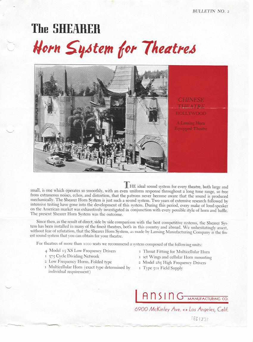
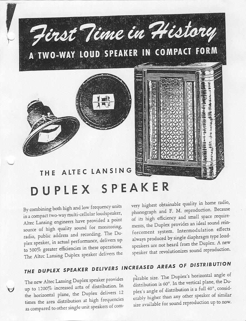
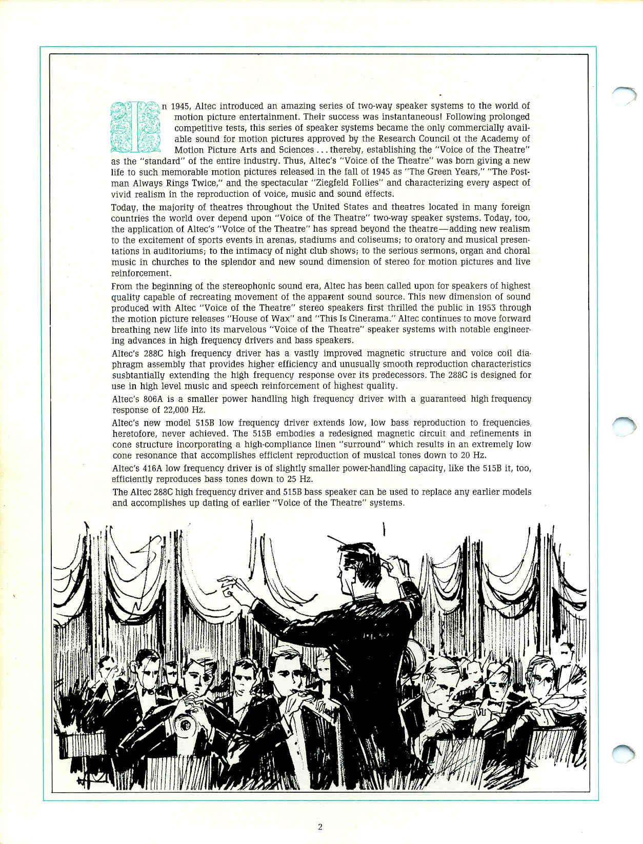
External links
[edit]- Conversion of sensitivity to energy efficiency in percent for passive loudspeakers
- Article on sensitivity and efficiency of loudspeakers (PDF)
| Music technology | |
|---|---|
| Sound recording | |
| Recording media | |
| Analog recording | |
| Playback transducers | |
| Digital audio | |
| Live music | |
| Electronic music | |
| Software | |
| Professions | |
| People and organizations | |
| Related topics | |
| International | |
|---|---|
| National | |
| Other | |
Loudspeaker
View on GrokipediaTerminology and Basics
Definitions and Scope
A loudspeaker is an electroacoustic transducer that converts electrical signals into sound waves through mechanical vibration of a diaphragm or similar element.[13] This process enables the reproduction of audio content, serving as a critical interface between electronic systems and human auditory perception.[14] The term "loudspeaker" originated in the late 19th century, first recorded around 1880–1885, as a compound of "loud" and "speaker," reflecting early devices designed to amplify speech from telephones or similar apparatus into audible sound.[15][16] In common usage, "speaker" serves as an informal abbreviation, while "driver" specifically denotes an individual transduction unit within a larger assembly.[17] The scope of loudspeakers encompasses both individual drivers—standalone electroacoustic units—and complete speaker systems, which integrate multiple drivers with enclosures, crossovers to optimize acoustic output.[17] These devices find application across professional settings such as concert venues and recording studios, consumer environments like home entertainment, and automotive interiors for in-vehicle audio.[18] Dynamic loudspeakers, employing a moving coil in a magnetic field, represent the most prevalent type.[19] At its core, sound production involves generating pressure waves in air, where variations in atmospheric pressure propagate as longitudinal waves detectable by the human ear.[20] The typical frequency range of human hearing spans approximately 20 Hz to 20 kHz, defining the audible spectrum that loudspeakers aim to reproduce faithfully.[21]Key Components and Concepts
A loudspeaker's fundamental operation relies on several core components that work together to convert electrical signals into audible sound. The driver is the primary electroacoustic transducer, responsible for transforming electrical energy into mechanical vibrations that produce acoustic waves.[22] Within the driver, the diaphragm (commonly referred to as the cone in cone-type drivers) serves as the radiating surface that displaces air to generate sound pressure; it is typically lightweight and rigid to ensure efficient motion. The voice coil, a coil of fine wire wound around a cylindrical former attached to the diaphragm, carries the audio current and interacts electromagnetically to drive the diaphragm's movement.[23] Surrounding the voice coil is the magnet (or magnetic assembly), which generates a static magnetic field essential for the Lorentz force that propels the coil and diaphragm.[24] The enclosure, or cabinet, houses the drivers and acoustically isolates the front and rear waves from the diaphragm to prevent phase cancellation and enhance bass response.[25] In multi-driver systems, a crossover network divides the input signal by frequency, directing low frequencies to woofers, mids to midrange drivers, and highs to tweeters for optimal performance across the audio spectrum. Key performance metrics quantify a loudspeaker's electrical, acoustic, and perceptual qualities. Impedance is the effective opposition to alternating current flow, expressed in ohms (Ω), with nominal ratings of 4 or 8 Ω being standard for consumer audio to match typical amplifiers. Frequency response characterizes the range and uniformity of reproduced frequencies, often specified as a bandwidth (e.g., 40 Hz to 20 kHz) with deviation tolerances like ±3 dB, indicating how faithfully the speaker reproduces the input signal across the audible spectrum. Distortion, particularly total harmonic distortion (THD), measures nonlinear alterations in the waveform as a percentage, where values below 1% at typical listening volumes (around 85-90 dB SPL) are desirable to minimize audible artifacts. Directivity describes the angular dispersion of sound, influencing coverage; it is often quantified via polar patterns or beamwidth angles, with wider directivity preferred for even room filling. Conceptual principles underpin these components' behavior. Piston motion refers to the ideal uniform displacement of the diaphragm as a rigid piston, producing coherent wavefronts at low frequencies where the wavelength exceeds the diaphragm diameter, ensuring efficient acoustic output.[26] At higher frequencies, breakup modes emerge as the diaphragm flexes unevenly due to its finite stiffness, leading to resonant vibrations that cause peaks, dips, and increased distortion in the response. Radiation patterns define spatial sound distribution: low-frequency sources approximate omnidirectional patterns, radiating equally in all directions, while high-frequency drivers exhibit directional (or beaming) characteristics, concentrating energy forward as wavelengths shorten relative to source size. Measurement units standardize evaluation. Sound pressure level (SPL) quantifies acoustic output in decibels (dB), referenced to 20 μPa, with speaker sensitivity typically rated as dB SPL at 1 meter for 1 watt input (e.g., 86-90 dB for many home systems). Power handling, rated in watts (continuous or peak), indicates the thermal and mechanical limits before damage, often 50-200 W for mid-sized drivers, balancing amplifier compatibility and output capability.History
Early Developments (Pre-1900)
The earliest precursors to modern loudspeakers emerged in the 17th and 18th centuries through mechanical acoustic devices designed to amplify human speech without electrical means. Speaking trumpets, essentially conical tubes that directed and intensified sound waves, were developed as early as 1670 by Sir Samuel Morland, a British mathematician and inventor, primarily for naval communication to project commands over distances at sea.[27] These devices operated on the principle of acoustic impedance matching, where the gradually expanding cone increased the effective radiating area of the voice, thereby enhancing audibility in open environments. By the 18th century, similar megaphones and ear trumpets—reversed versions for hearing assistance—had become common, with refinements by figures like Athanasius Kircher, who in 1673 described the "tuba stentorophonica," a multi-stage trumpet capable of projecting sound over a mile.[28] These passive acoustic amplifiers laid foundational concepts for sound projection, influencing later designs by demonstrating how shape and material could manipulate wave propagation.[27] The 19th century marked the transition to electroacoustic principles, beginning with inventions that coupled electrical signals to mechanical vibration for sound reproduction. In 1876, Alexander Graham Bell patented the telephone (U.S. Patent No. 174,465), which featured a receiver with a thin diaphragm attached to an armature positioned near an electromagnet; incoming electrical currents varied the magnetic field, causing the diaphragm to vibrate and produce audible sound waves.[29] This electromagnetic transduction mechanism—where electrical undulations drove diaphragm motion—served as a direct precursor to loudspeaker technology, enabling the conversion of telegraph-like signals into intelligible speech, though with limited volume.[29] Bell's device demonstrated the feasibility of electrodynamic sound generation, bridging acoustic and electrical domains in a compact form. Shortly thereafter, in 1877, Thomas Edison invented the phonograph, the first practical device for recording and reproducing sound, which utilized an acoustic horn to amplify playback from a vibrating diaphragm.[30] The playback mechanism involved a stylus tracing grooves on a tinfoil-wrapped cylinder, causing a diaphragm to replicate the original vibrations; the attached horn exponentially expanded these weak acoustic signals, increasing efficiency and directivity for listener perception.[30] Edison's design emphasized mechanical fidelity in reproduction, with the horn serving as a passive amplifier to overcome the inherent inefficiency of small diaphragms.[31] That same year, Ernst Werner von Siemens developed an early electrodynamic receiver for telegraphic and telephonic use, featuring a coil suspended in a magnetic field that, when energized, moved a diaphragm to generate sound— an advancement over static receivers by introducing dynamic motion for clearer audio output.[32] This device, patented in variations around 1875-1877, represented one of the first instances of a moving-coil principle in electroacoustics, where current through the coil interacted with the magnetic field to produce proportional diaphragm excursion, foreshadowing modern driver architectures.[32] Siemens' contribution highlighted the potential for scalable sound transduction, influencing subsequent refinements in electrical audio transmission.Invention of Dynamic Speakers (1900-1940)
The invention of dynamic loudspeakers marked a pivotal shift toward electromagnetic transduction for audio reproduction, building briefly on principles from telephone receivers developed in the late 19th century. In 1898, British physicist Sir Oliver Lodge patented the first moving-coil loudspeaker design, described in British Patent No. 9712 filed on April 27 of that year.[33] Lodge's innovation featured a lightweight coil attached to a diaphragm, suspended within a strong magnetic field, allowing electrical signals to drive the coil and produce vibrations for sound output; this laid the foundational concept for modern dynamic drivers, though practical implementation awaited further refinements. A significant step toward practicality occurred in 1915, when Danish-American engineer Peter L. Jensen and American engineer Edwin S. Pridham developed the first effective moving-coil loudspeaker in Napa, California. Known as the "Magnavox" (Latin for "great voice"), this device used a paper cone driven by a voice coil in a magnetic field to produce loud, clear sound from electrical signals, enabling applications in public address systems. It was publicly demonstrated in 1916, including during a speech by President Woodrow Wilson.[8] Early 20th-century advancements focused on improving diaphragm materials and acoustic efficiency, particularly for horn-loaded designs used in emerging radio broadcasting. In 1901, engineer John Stroh described the conical paper diaphragm, which terminated at the rim of the speaker frame to enhance rigidity and reduce distortion, a design that became integral to horn speakers.[33] By the 1920s, these horn speakers, often incorporating balanced-armature or early dynamic drivers, were widely adopted for early radios, providing amplified output for home listening despite limitations in frequency response and volume; examples include the gooseneck horns from manufacturers like Amplion, which resonated with the low-power transmitters of the era.[16] A breakthrough came in 1925 when engineers Chester W. Rice and Edward W. Kellogg at General Electric developed the first practical direct-radiator dynamic loudspeaker, detailed in their seminal paper "Notes on the Development of a New Type of Hornless Loud-Speaker." Their design employed a moving-coil voice coil attached to a conical paper cone with carefully tuned stiffness and mass to minimize breakup modes—vibrational distortions that fragmented sound waves—achieving uniform response across mid-frequencies without relying on bulky horns for efficiency.[33] This innovation enabled compact, efficient speakers suitable for broader applications, patented under U.S. Patent No. 1,707,430 in 1929 but prototyped earlier. Commercialization accelerated in the mid-1920s with Western Electric's deployment of theater loudspeaker systems, starting with the No. 1-A installation in 1926 for synchronized sound films like Warner Bros.' Vitaphone process.[34] These systems used large horn-loaded dynamic drivers, such as the 12A and 13A models, to deliver high-volume, clear audio to audiences, powering the transition to "talkies" in cinemas.[16] By the 1930s, dynamic loudspeakers had entered consumer homes through affordable radio sets, with RCA producing models featuring 10-inch Rice-Kellogg-style cones that provided balanced sound for everyday broadcasting, marking the widespread adoption of electromagnetic speakers before World War II.[33]Modern Evolution (Post-1940)
Following World War II, the loudspeaker industry experienced rapid growth driven by the popularization of high-fidelity (hi-fi) audio systems in the 1950s, as rising middle-class affluence and hobbyist electronics enabled consumers to assemble separate components like turntables, amplifiers, and speakers for superior sound reproduction.[35] Stereo sound, which used two channels to create a more immersive listening experience, gained commercial traction around 1958, marking a shift from monaural systems and laying the foundation for modern home audio setups.[36] A notable innovation during this era was the Klipschorn horn-loaded loudspeaker, introduced in 1946 by Paul W. Klipsch, which utilized a corner-placed folded horn design to achieve high efficiency and dynamic range without requiring excessive power, influencing subsequent high-sensitivity speaker architectures.[37] In the 1970s, the introduction of Thiele-Small parameters provided a standardized set of electromechanical metrics—such as resonance frequency (Fs) and total Q factor (Qts)—that allowed engineers to precisely model and optimize loudspeaker enclosure designs for improved bass response and overall performance.[38] Developed initially by A. Neville Thiele in the 1960s and expanded by Richard H. Small through publications in the early 1970s, these parameters became essential for vented-box alignments and remain a cornerstone of driver specification.[39] The 1970s and 1980s saw the rise of active loudspeakers, where built-in amplifiers per driver enabled better power matching and reduced cabling complexity, initially in professional audio before entering home systems.[40] By the 1990s, digital signal processing (DSP) integration transformed loudspeaker performance; Meridian Audio's DSP6000, launched in 1990, was the first commercial speaker to employ DSP for real-time equalization and crossover management, enhancing accuracy across frequencies.[41] Concurrently, subwoofers surged in popularity for home audio, particularly with the advent of home theater systems in the late 1980s and 1990s, as they dedicated low-frequency reproduction (below 100 Hz) to larger drivers, improving bass extension without compromising midrange clarity.[42] From the 2000s onward, micro-electro-mechanical systems (MEMS) drivers emerged as compact alternatives to traditional dynamic speakers, leveraging silicon-based diaphragms for integration into portable devices like smartphones, with significant advancements in the 2010s enabling higher sound pressure levels up to 140 dB and broader frequency response.[43] Three-dimensional (3D) printing revolutionized enclosure fabrication starting in the early 2010s, allowing custom geometries that minimize internal resonances and optimize acoustics, as demonstrated in prototypes like Novel Acoustics' solid-printed cabinets for enhanced rigidity and reduced material waste.[44] In the 2020s, artificial intelligence (AI) has optimized loudspeaker designs through algorithms that simulate acoustic interactions, predict room responses, and automate crossover tuning, enabling adaptive systems that adjust in real-time for immersive spatial audio.[45] Sustainability efforts have also advanced, with consumer models incorporating bioplastics and recycled polymers in enclosures to lower environmental impact; for instance, by 2024, manufacturers like Martin Audio adopted 85% post-consumer recycled ABS, reducing carbon emissions by over 50% per kilogram compared to virgin materials.[46]Operating Principles
Electromagnetic Transduction
Electromagnetic transduction in dynamic loudspeakers primarily relies on the interaction between an electrical current in a voice coil and a static magnetic field to produce mechanical motion. The voice coil, typically wound with fine copper wire, is suspended within the air gap of a permanent magnet assembly, where it experiences a uniform magnetic field B. When an audio signal drives an alternating current I through the coil, the Lorentz force acts on the current-carrying conductors, generating a mechanical force perpendicular to both the field and current directions. This force, given by , where L is the effective length of wire immersed in the field, propels the coil and attached diaphragm forward or backward depending on the current's polarity, converting electrical energy into linear motion. The magnitude of this transduction is quantified by the force factor Bl, defined as the product of the magnetic flux density B and the effective length l of the voice coil in the gap, such that the total force simplifies to . This Bl parameter is a critical design metric, as higher values enhance the efficiency of force generation for a given current, influencing the loudspeaker's sensitivity and power handling. In practice, Bl is optimized by maximizing the magnetic field strength and coil length while minimizing gap size, though nonlinear variations with coil position x (Bl(x)) can introduce distortion if not managed.[47] As the voice coil moves due to the applied force, it cuts magnetic flux lines, inducing an electromotive force (EMF) according to Faraday's law of electromagnetic induction, which states that the induced EMF , where is the magnetic flux. For the voice coil, this back-EMF opposes the applied voltage and is proportional to the coil's velocity v, expressed as . This induced voltage creates a current that generates a counter-force, providing electromagnetic damping that stabilizes the motion and reduces resonance ringing. In audio applications, the alternating current from the AC signal produces oscillatory motion at the signal frequency, with the back-EMF ensuring controlled response across the bandwidth.[47][48]Acoustic Radiation and Efficiency
The acoustic radiation from a loudspeaker arises from the mechanical vibrations of the diaphragm, which is typically modeled as a baffled piston radiator assuming uniform piston-like motion across its surface when the sound wavelength is much larger than the diaphragm diameter. This model approximates the behavior of a boxed loudspeaker, where the baffle prevents sound radiation from the rear, effectively doubling the forward radiation compared to an unbaffled source. In this regime, the diaphragm acts as an acoustic monopole source, compressing and rarefying the air to produce spherical wavefronts that propagate outward.[49] The total radiated acoustic power in the far field for this low-frequency approximation is given by where is the density of air, is the speed of sound, is the wavenumber with frequency , is the effective area of the diaphragm, and is the velocity of the diaphragm surface. This expression derives from integrating the acoustic intensity over a spherical surface enclosing the source, highlighting the quadratic dependence on frequency and velocity, which underscores the challenge of efficient low-frequency radiation. At higher frequencies, where the diaphragm size approaches or exceeds the wavelength (, with the radius), the radiation pattern transitions from omnidirectional to directional, with the directivity index increasing as the sound beams into a narrower forward lobe, typically around 55° at moderate and narrowing to about 20° at high , accompanied by weaker sidelobes. This beaming effect concentrates energy on-axis but reduces off-axis coverage, influencing loudspeaker directivity.[49][50] The overall acoustic efficiency of dynamic loudspeakers, defined as the ratio of radiated acoustic power to input electrical power, is fundamentally limited by the impedance mismatch between the high mechanical impedance of the diaphragm assembly and the low radiation impedance of air, particularly at low frequencies where radiation resistance is negligible compared to the driver's inertial and stiffness reactances. This mismatch results in most input power being dissipated as heat in the voice coil rather than radiated as sound, with typical efficiencies below 1% for direct-radiating dynamic drivers. Horn enclosures can improve efficiency by transforming the air load to better match the driver impedance, but inherent limits persist due to the small radiation resistance of planar sources in free air.[51]Dynamic Loudspeaker Design
Diaphragm and Suspension
The diaphragm in a dynamic loudspeaker serves as the primary radiating surface, converting mechanical vibrations from the voice coil into acoustic waves through piston-like motion at low frequencies and more complex modal behavior at higher ones. Common diaphragm shapes include the cone, which provides broad dispersion and is typically used in woofers and midrange drivers, and the dome, suited for tweeters due to its compact size and high-frequency response. Cone diaphragms are often constructed from paper, valued for its lightweight nature and inherent damping properties that help control resonances, or polypropylene, a molded plastic offering greater rigidity and moisture resistance for improved durability in demanding environments. Dome diaphragms frequently employ silk for its smooth high-frequency extension and low mass, or metal alloys like aluminum or titanium for enhanced stiffness that supports operation up to ultrasonic frequencies. Breakup modes occur when the diaphragm's dimensions become comparable to the wavelength of the sound being reproduced, causing partial vibrations that deviate from uniform motion and introduce distortion peaks in the frequency response. These modes are mitigated through resonance control strategies, such as material doping or composite layering in paper cones to raise breakup frequencies beyond the driver's operating range, or by using beryllium in metal domes for its exceptional stiffness-to-weight ratio that delays onset of such irregularities. In polypropylene cones, controlled breakup is achieved via precise molding to balance rigidity with flexibility, ensuring smoother off-axis response compared to untreated paper variants. The suspension system anchors the diaphragm while permitting linear excursion and centering the voice coil within the magnetic gap to maintain consistent electromagnetic coupling. It comprises two main elements: the surround, a flexible rim typically made of rubber or foam that seals the driver and attaches the diaphragm periphery to the frame, and the spider, an inner corrugated fabric suspension—often cotton, nomex, or progressive-woven synthetics—that provides axial stability and prevents lateral tilt. The surround contributes to high-frequency compliance and damping, absorbing edge resonances, while the spider dominates low-frequency stiffness, ensuring voice coil alignment during large excursions. Compliance, denoted as Cms in Thiele-Small parameters, quantifies the suspension's flexibility in meters per newton and directly influences the driver's overall mechanical behavior, with higher values enabling deeper bass extension but risking instability if excessive. Material selection for both diaphragm and suspension involves inherent trade-offs between stiffness, which resists breakup and maintains piston motion, and damping, which dissipates unwanted vibrations to minimize distortion—rigid materials like metal excel in the former but may ring harshly without added damping layers, whereas damped options like paper or foam surrounds reduce peaks at the cost of slightly higher moving mass. Optimal designs balance these via hybrid constructions, such as foam surrounds impregnated with adhesives for tunable viscoelastic properties that help reduce harmonic distortion in the midrange. The resonant frequency Fs of the driver, determined primarily by suspension stiffness k (in N/m) and moving mass m (in kg including diaphragm and coil), is calculated as , providing a critical benchmark for low-frequency performance where the system naturally amplifies motion.Voice Coil and Magnetic Assembly
The voice coil serves as the electromagnetic actuator in a dynamic loudspeaker, consisting of fine wire windings typically made of copper or aluminum, coiled around a cylindrical former or bobbin. Copper is the most commonly used material due to its superior electrical conductivity and cost-effectiveness, while aluminum offers reduced weight for applications requiring lighter drivers, and copper-clad aluminum wire provides a balance of both properties.[52][53] The former, often constructed from heat-resistant materials such as Kapton polyimide film or aluminum, supports the windings and ensures structural integrity during linear excursions, with the coil immersed in the magnetic gap to interact with the field for force generation.[52][54] During operation, the voice coil generates heat from electrical current, leading to thermal expansion of the wire and former, which increases the DC resistance (Re) and thus raises the overall impedance, potentially reducing sensitivity and altering damping characteristics. This impedance rise becomes significant above 100–150°C, where resistance can increase by 20–50%, impacting power handling and low-frequency control unless mitigated by advanced cooling designs.[55][56] The magnetic assembly provides the static field for transduction, primarily using permanent magnets such as ferrite (ceramic) or neodymium-iron-boron (NdFeB), with the latter emerging in the early 1980s to enable compact, high-performance drivers due to its superior magnetic energy density. Ferrite magnets, valued for their affordability and thermal stability, dominate cost-sensitive applications, while NdFeB allows for smaller assemblies with greater efficiency in professional and high-end consumer speakers. The magnetic gap flux density typically ranges from 0.5 to 2 Tesla, with ferrite structures often achieving 0.4–1 T and neodymium designs reaching up to 2 T or more for enhanced force factors (Bl).[57][58][59] Field shaping in the assembly relies on a top plate (or washer), bottom plate, and central pole piece, all typically soft iron or steel, which concentrate and direct the flux lines radially across the gap surrounding the voice coil. The bottom plate sandwiches the magnet against the pole piece base, while the top plate caps the structure, ensuring uniform field density (B) in the annular gap, typically 1–3 mm wide, to minimize distortion from flux modulation during coil motion.[60][24][61] These components contribute to key Thiele-Small parameters that quantify damping: Qes (electrical quality factor) arises from energy losses due to voice coil resistance (Re) and inductance (Le) interacting with the magnetic field, reflecting back-EMF damping; Qms (mechanical quality factor) stems from suspension friction and material losses; and Qts (total quality factor) combines them as , governing overall resonance control and enclosure suitability. Lower Qes values indicate stronger electrical damping from efficient coil-magnet interaction, while Qms highlights mechanical contributions, with typical Qts ranging from 0.2–0.7 for balanced performance.[10][62][63]Frame and Structural Elements
The frame, often referred to as the basket or chassis, serves as the foundational structure in dynamic loudspeakers, providing mechanical support for the magnet assembly, voice coil, and diaphragm while ensuring overall rigidity to minimize unwanted vibrations.[22] It typically anchors the magnetic assembly, allowing for precise alignment and stability during operation.[22] Common materials for loudspeaker baskets include stamped steel, cast aluminum, and plastic composites, each selected for their balance of cost, rigidity, and functional properties. Stamped steel baskets are widely used in budget and mid-range drivers due to their cost-effectiveness and ease of manufacturing, though they offer moderate rigidity that aids in basic vibration isolation by distributing mechanical stresses across the structure.[22] Cast aluminum provides superior rigidity and vibration isolation, making it ideal for high-performance drivers where structural integrity prevents flexing that could couple vibrations to the enclosure.[22] Plastic baskets, reinforced with glass fibers, are employed in smaller drivers (up to 6 inches) for lightweight applications, offering adequate vibration isolation through their inherent damping properties while reducing overall weight.[22] Heat management is a critical function of the frame, particularly in dissipating thermal energy from the voice coil to prevent efficiency losses known as thermal compression. Cast aluminum frames excel as heat sinks due to their high thermal conductivity, conducting heat away from the voice coil former and reducing temperature rise during prolonged operation.[22] Many designs incorporate fins or extended surfaces on the frame to increase surface area for convective cooling, while vents integrated into the basket or adjacent structures facilitate airflow, lowering the voice coil's thermal resistance and mitigating compression effects where impedance rises and output drops by up to 3-6 dB at high power levels.[64][55] In advanced configurations, dedicated heat sink members attached directly to the frame enhance dissipation, drawing heat via conduction paths to the exterior.[65] Mounting flanges on the basket enable secure integration into enclosures or systems, typically featuring circumferential lips with pre-drilled holes following patterns scaled to driver diameter—with a typical bolt circle diameter of about 6 inches for 6.5-inch drivers. These flanges, often 0.5-1 inch wide, accommodate standard machine screws (e.g., #6 or M4) to ensure airtight seals and vibrational decoupling from the cabinet.[66][67] To suppress resonances that could propagate to the cabinet, frames often receive damping treatments such as proprietary resonant coatings or constrained-layer materials applied to the basket surfaces, which convert vibrational energy into heat and reduce ringing modes effectively.[68] High-stiffness designs with integrated internal damping further control resonances, maintaining clarity by isolating the driver from structural modes.[69]Driver Categories
Full-Range and Broadband Drivers
Full-range and broadband drivers are single loudspeaker units engineered to reproduce the substantial portion of the audible frequency spectrum, typically spanning from around 80 Hz to 15 kHz, with primary design goals of achieving wide horizontal dispersion for even coverage and maintaining low distortion levels across the operating range.[70] These drivers prioritize coherent wavefront emission from a single radiating source, minimizing phase issues inherent in divided-band systems and simplifying overall assembly by eliminating crossover components.[71] The focus on broadband response allows for a more unified tonal balance, where midrange clarity drives the overall character, though achieving uniform efficiency and directivity remains challenging due to the compromises in driver size and cone dynamics.[72] Pioneering examples trace back to the 1930s, such as the Wharfedale Bronze drive unit developed by Gilbert Briggs in 1932, which utilized a lightweight cone material to extend response beyond typical drivers of the era and became a benchmark for early full-range performance in home audio.[73] In modern contexts, field coil drivers—employing electromagnetically generated fields instead of permanent magnets—represent a revival, with examples like the Atelier Rullit 10-inch Super Aero units delivering high sensitivity (around 100 dB/W/m) and dynamic range suitable for boutique hi-fi applications.[74] These designs often feature optimized voice coil and suspension systems to balance excursion demands across frequencies, though they retain the single-cone architecture central to full-range philosophy. Despite their strengths, full-range drivers exhibit notable limitations, including inadequate bass extension below 80 Hz owing to the cone's limited surface area and mass, which restricts low-frequency air displacement without additional augmentation.[70] Midrange beaming poses another constraint, as larger cone diameters (typically 8-12 inches) cause narrowing of the off-axis response above 2-3 kHz, reducing dispersion at higher frequencies and potentially creating uneven listening areas.[71] To mitigate treble roll-off, many incorporate whizzer cones—small, lightweight secondary diaphragms attached to the main cone that independently vibrate for frequencies above 5 kHz—though this can introduce minor resonances if not precisely tuned.[22] These drivers find primary applications in public address (PA) systems, where their compact form, high efficiency, and straightforward integration support reliable voice and music reinforcement in venues like theaters and conference halls.[71] In vintage hi-fi circles, they remain sought after for their natural, uncolored midrange reproduction, often paired with transmission line or open-baffle enclosures to enhance perceived bass without compromising the single-driver ethos.[75] Compared to multi-driver setups, full-range designs provide superior point-source coherence but at the cost of specialized frequency optimization.Specialized Frequency Drivers
Specialized frequency drivers are loudspeaker components engineered to reproduce specific segments of the audio spectrum with optimized performance, allowing for multi-driver systems that achieve broader and more accurate frequency response when integrated via crossover networks. These drivers include woofers for low to mid frequencies, midrange drivers for the critical vocal band, tweeters for high frequencies, and subwoofers for deep bass extension. In a typical 3-way speaker system, the woofer handles low frequencies (bass), the midrange driver covers approximately 300 Hz to 5 kHz, and the tweeter reproduces high frequencies above 5 kHz. Each type features distinct design elements, such as diaphragm size, material, and excursion capabilities, tailored to minimize distortion and maximize efficiency within their operational range. Woofers typically operate in the 40-2000 Hz range, handling bass and lower midrange frequencies with large cone diameters—often 6 to 15 inches—to achieve sufficient air displacement for robust low-end output. Their design emphasizes high linear excursion, with Xmax values exceeding 5 mm, enabling the voice coil to move substantial distances without nonlinear distortion, which is essential for reproducing dynamic bass content. These drivers commonly use treated paper or composite cones for rigidity and damping, paired with robust surrounds to support extended travel while maintaining piston-like motion up to several hundred Hz.[22][76] Midrange drivers cover approximately 200-5000 Hz, the frequency band most sensitive to human hearing and crucial for vocal clarity and instrumental timbre. Featuring smaller cones or domes—typically 3 to 6 inches—these drivers prioritize smooth response and low coloration to preserve mid-frequency detail, often employing lightweight materials like coated paper, polypropylene, or aluminum domes for reduced breakup modes. Their compact size allows for precise control and wide dispersion in this range, enhancing intelligibility in speech and music reproduction without the mass required for bass handling.[77][22] Tweeters are designed for frequencies above 5000 Hz, extending to 20 kHz or beyond to capture harmonic overtones and airiness in audio signals. Common types include soft dome tweeters made from silk or fabric for smooth off-axis response and compression drivers, which use a small throat coupled to a horn to increase efficiency and directivity at high frequencies. Dome designs feature diaphragms under 1 inch in diameter to ensure fast transient response and minimal resonance, while compression drivers incorporate annular diaphragms and phase plugs to handle high power levels with controlled directivity, making them suitable for professional applications.[22][78] Subwoofers specialize in frequencies below 100 Hz, delivering impactful deep bass for home theater and music systems through high-power amplification and large drivers—often 10 to 18 inches—with excursion capabilities far exceeding those of standard woofers. Ported (bass-reflex) designs dominate, incorporating tuned vents to augment low-frequency output by 3-6 dB near the port resonance, enabling higher sound pressure levels with less driver effort. THX certification for home theater subwoofers mandates performance standards including a minimum 115 dB peak output capability at low frequencies (down to 20 Hz), low distortion to 20 Hz, and robust construction to ensure consistent bass reproduction across room positions.[79][80][81] Boundary effects significantly influence specialized drivers, particularly at low frequencies where proximity to room surfaces like walls or floors can boost output by up to 6 dB per boundary due to constructive interference, altering the effective roll-off characteristics. For woofers and subwoofers, this reinforcement extends the low-end response but may introduce unevenness if not accounted for, with roll-off slopes steepening near room modes; tweeters and midranges experience less impact, though off-axis placement can cause high-frequency attenuation. These interactions necessitate careful positioning to balance direct and reflected sound for uniform frequency response.[82][83]Compound and Coaxial Drivers
Compound and coaxial drivers represent integrated multi-element designs that combine multiple transduction units within a single chassis to enhance acoustic coherence and simplify system integration. These configurations address limitations of discrete drivers by aligning the acoustic centers of low-, mid-, and high-frequency elements, minimizing phase discrepancies and improving off-axis response.[84] Coaxial drivers feature a high-frequency transducer, such as a tweeter or compression driver, mounted at the apex or center of a larger low-frequency cone or diaphragm, enabling sound radiation from a virtual point source. This design originated with the Tannoy Dual Concentric driver, patented in 1951 but first developed in 1947, where a small high-frequency unit is positioned within the voice coil gap of a larger woofer to achieve concentric emission.[85] The approach ensures that all frequencies propagate from the same spatial origin, reducing time-of-arrival differences that cause comb filtering in multi-driver arrays. A prominent modern example is the KEF Uni-Q array, introduced in 1988, which places a tweeter at the acoustic center of a midrange cone, promoting uniform dispersion and eliminating the narrow "sweet spot" typical of conventional setups.[86] The benefits of coaxial configurations include point-source radiation patterns that deliver consistent frequency response across wide listening angles, as the high- and low-frequency waves expand spherically from one point without significant interference. This minimizes lobing—uneven vertical and horizontal radiation lobes caused by path-length differences in separated drivers—resulting in smoother polar response, particularly above 500 Hz.[84] In professional audio, coaxial drivers facilitate compact line arrays, such as L-Acoustics' X Series systems, where multiple coaxial units are arrayed to maintain phase coherence over distance while reducing array-induced distortions.[87] Compound drivers extend this integration through stacked or nested elements optimized for phase alignment, often combining multiple diaphragms or voice coils in a shared magnetic structure to extend bandwidth and control directivity. These designs, such as those using dual concentric or isobaric configurations, enhance efficiency and transient response by coupling mechanical motions for unified wavefront propagation. Examples include pro audio compression drivers like the B&C DCX464, which stack midrange and high-frequency diaphragms in a single throat for seamless crossover transitions around 3 kHz, supporting high-SPL applications in point-source cabinets and line arrays.[84] Overall, both compound and coaxial approaches prioritize acoustic unity, making them ideal for applications demanding precise imaging and broad coverage without complex external processing.[88]System Assembly and Enclosures
Crossover Networks
Crossover networks are electronic circuits designed to divide an audio signal into frequency bands that are directed to appropriate loudspeaker drivers, such as woofers for low frequencies and tweeters for high frequencies, ensuring each driver operates within its optimal range.[89] These networks can be passive, utilizing components placed after the amplifier, or active, processing line-level signals before amplification. Passive crossovers are simpler and cost-effective for basic systems, while active designs offer greater flexibility and precision in multi-driver setups.[90] In passive crossover networks, the primary components are inductors, capacitors, and resistors, which form low-pass, high-pass, or band-pass filters based on their reactive properties. Inductors impede high-frequency signals, with inductance calculated as , where is voltage, is frequency, and is current, derived from the inductive reactance .[91] Capacitors, conversely, block low frequencies, with capacitance given by , from the capacitive reactance .[91] Resistors are used for attenuation or impedance matching to balance output levels between drivers.[92] Filter order determines the steepness of the frequency roll-off; a first-order crossover, using a single inductor or capacitor per section, provides a gentle 6 dB/octave slope, resulting in minimal phase shift but broader overlap between drivers.[93] Higher-order filters, such as second-order (12 dB/octave) or fourth-order (24 dB/octave), employ multiple components for steeper attenuation, reducing inter-driver interference but introducing more complex phase responses. The Linkwitz-Riley alignment, a fourth-order design with a 24 dB/octave slope, ensures flat summation of outputs and in-phase recombination at the crossover frequency, as originally proposed for active systems with non-coincident drivers.[94] All crossover filters introduce phase shifts that vary with frequency, potentially causing time misalignment between drivers and audible artifacts like altered soundstage imaging. Group delay, the frequency-dependent propagation time through the filter, exacerbates this in higher-order designs, where low-pass sections may lag high-pass ones by up to 360 degrees at the crossover point. All-pass filters, which maintain constant magnitude response while adjusting phase, are often employed to correct these discrepancies by equalizing delay without altering amplitude.[95][96] Active crossover networks process signals using operational amplifiers or digital signal processors (DSP), bypassing the power losses of passive components and allowing independent amplification per band. In modern amplifiers from the 2020s, DSP implementations predominate, utilizing infinite impulse response (IIR) filters for efficient analog-like behavior or finite impulse response (FIR) filters for linear-phase correction with minimal group delay distortion. These enable precise tailoring to driver frequency responses, such as compensating for a tweeter's roll-off above 5 kHz.[97][98][99]Enclosure Types and Designs
Loudspeaker enclosures significantly influence driver performance by managing rear radiation, enhancing bass response, and minimizing unwanted resonances. The choice of enclosure type affects frequency extension, efficiency, and transient accuracy, with designs tailored to the driver's Thiele-Small parameters for optimal acoustic loading. Common basic shapes include rectangular boxes for sealed and ported types, while open configurations suit free-air applications.[100] Sealed enclosures, also known as acoustic suspension systems, consist of an airtight cabinet where the trapped air volume acts as a spring to complement the driver's mechanical suspension. This air spring provides damping that controls cone excursion, resulting in precise bass reproduction with low distortion and good transient response, particularly beneficial for midbass drivers. The system's overall damping is characterized by the total Q factor, Qtc, which combines the driver's Qts and the enclosure's acoustic compliance; Qtc is tuned by adjusting the enclosure volume Vb relative to the driver's Vas, with values around 0.707 yielding a maximally flat amplitude response and Qtc >1 producing a slight peak for extended but less accurate bass. Smaller volumes increase Qtc for higher efficiency but risk overdamping and boominess, while larger volumes lower Qtc for smoother roll-off at the expense of output. Acoustic suspension designs excel in compact applications, offering simplicity and phase coherence across the passband without vent-related delays.[101][102] Ported enclosures, or bass reflex systems, feature a vent or port that couples the driver's rear output to the front, leveraging Helmholtz resonance to augment low-frequency response. The port's air mass oscillates with the enclosure's air spring, reinforcing bass at the tuning frequency and extending the system's -3 dB point lower than a comparable sealed design, often by 3-6 dB gain near resonance for improved efficiency in subwoofer applications. The resonance frequency is determined by the formula where is the speed of sound (approximately 343 m/s), is the port cross-sectional area, is the enclosure net volume, and is the effective port length (including end corrections). Tuning slightly above the driver's free-air resonance Fs enhances flatness, but mismatches can cause peaking or reduced output below , where the response rolls off steeply. Ported designs demand careful driver selection to avoid over-excursion, and they integrate with crossovers to filter high frequencies from the woofer.[103][104] Free-air and infinite baffle configurations eliminate traditional enclosures, mounting the driver on a large, rigid baffle to isolate front and rear waves without confinement. In free-air setups, the driver operates in open space, relying on its inherent resonance for bass, which suits lightweight cones with high Qts for natural decay but limits low-end extension due to dipole cancellation. Infinite baffle approximates an unlimited rear volume, typically using a sealed wall or vast enclosure (Vb >> Vas) to prevent back pressure, preserving the driver's Qts and Fs while suppressing box resonances for clean, uncolored output. These designs are common in automotive audio, where vehicle compartments serve as baffles, and in open-baffle speakers for spacious imaging, though they require drivers with robust suspensions to handle unrestricted excursion.[105][106] Damping materials are essential in enclosed designs to mitigate internal standing waves, which form when parallel surfaces reflect sound, creating peaks and nulls that color the frequency response. Polyfill, a synthetic fiber stuffing, is widely used as it absorbs mid-to-high frequency energy through friction, effectively slowing the speed of sound inside the enclosure by up to 15-20% and simulating a larger volume (up to 40% increase) without altering low-frequency compliance significantly. This reduces standing wave amplitude, particularly at quarter-wavelength multiples of enclosure dimensions (e.g., ~200-500 Hz in typical boxes), preventing resonances that cause harshness or uneven driver loading. Optimal filling—about 0.5-1 lb/ft³ loosely distributed—balances absorption with ventilation; excessive polyfill over-damps highs, while insufficient allows echoes, and alternatives like acoustic foam target walls for panel vibration control. Enclosures integrate damping with crossover networks for holistic performance tuning.[107][108]Advanced Enclosure Variants
Advanced enclosure variants, such as horns and transmission lines, extend the principles of basic loudspeaker cabinets by incorporating acoustic waveguides that improve efficiency, control directivity, and extend low-frequency response through specialized geometries. These designs leverage wave propagation and resonance to couple the driver more effectively to the air, often achieving higher sensitivity at the cost of increased physical size and construction complexity. Horn enclosures, in particular, amplify sound pressure via a flaring structure, while transmission lines use elongated, damped paths to manage rear radiation and resonances. Horn loudspeakers employ progressively expanding cross-sections to match the driver's output impedance to the free air, enhancing efficiency and directivity. Common profiles include the exponential horn, where the radius grows as with as the flare constant and the throat radius, providing consistent loading over a broad bandwidth but potentially introducing higher-order modes at low frequencies. The tractrix profile, derived from the path of a pulled object under constant tension, offers smoother wavefront expansion and reduced distortion, making it suitable for midrange and high-frequency applications by preserving spherical wave characteristics longer than exponential designs. The mouth size critically determines low-frequency loading, with the cutoff frequency given by , where is the speed of sound (approximately 343 m/s) and is the mouth radius; this ensures impedance matching below which the horn behaves as a high-pass filter. A seminal example is the Klipschorn, introduced in 1946 by Paul W. Klipsch, which utilizes a folded exponential horn in a corner-loaded configuration to achieve high sensitivity (around 105 dB/W/m) while minimizing cabinet size by exploiting room walls as extensions of the horn mouth. Horn designs excel in efficiency, often delivering 10-15 dB more output than direct-radiating drivers for the same power input, and provide controlled directivity to reduce room reflections, but they require large dimensions—frequently several feet across—for bass extension and demand precise engineering to avoid resonances and beaming. Transmission line enclosures guide the driver's rear wave through a long, folded duct tuned to a quarter-wavelength resonance, absorbing energy via damping materials to suppress unwanted peaks. The labyrinthine path, often filled with acoustic foam or fiber, attenuates higher harmonics while reinforcing bass at the line's fundamental frequency, effectively damping the quarter-wave standing wave that would otherwise cause cabinet vibrations. This results in smoother frequency response and tighter bass compared to ported boxes, with the line length typically set to where is the desired resonance frequency, adjusted for stuffing to lower effective speed of sound. A variant is the tapered quarter-wave tube (TQWT), which incorporates a conical flare to broaden the resonance bandwidth and improve midbass efficiency, originating from Paul Voigt's 1934 patent and popularized in modern designs for full-range drivers. Examples include TQWT systems using small broadband units, achieving extended low-end response in compact forms. These enclosures offer advantages in bass definition and reduced distortion due to minimal cone excursion, but disadvantages include greater internal volume and fabrication challenges from the intricate folding, leading to higher costs and sensitivity to design errors.| Enclosure Type | Key Advantage | Key Disadvantage |
|---|---|---|
| Horn | High efficiency (up to 105 dB/W/m) and directivity control | Large size and construction complexity |
| Transmission Line | Smooth, extended bass with low distortion | Increased cabinet volume and damping material requirements |