
Community hub
Recent from talks
Contribute something
Nothing was collected or created yet.
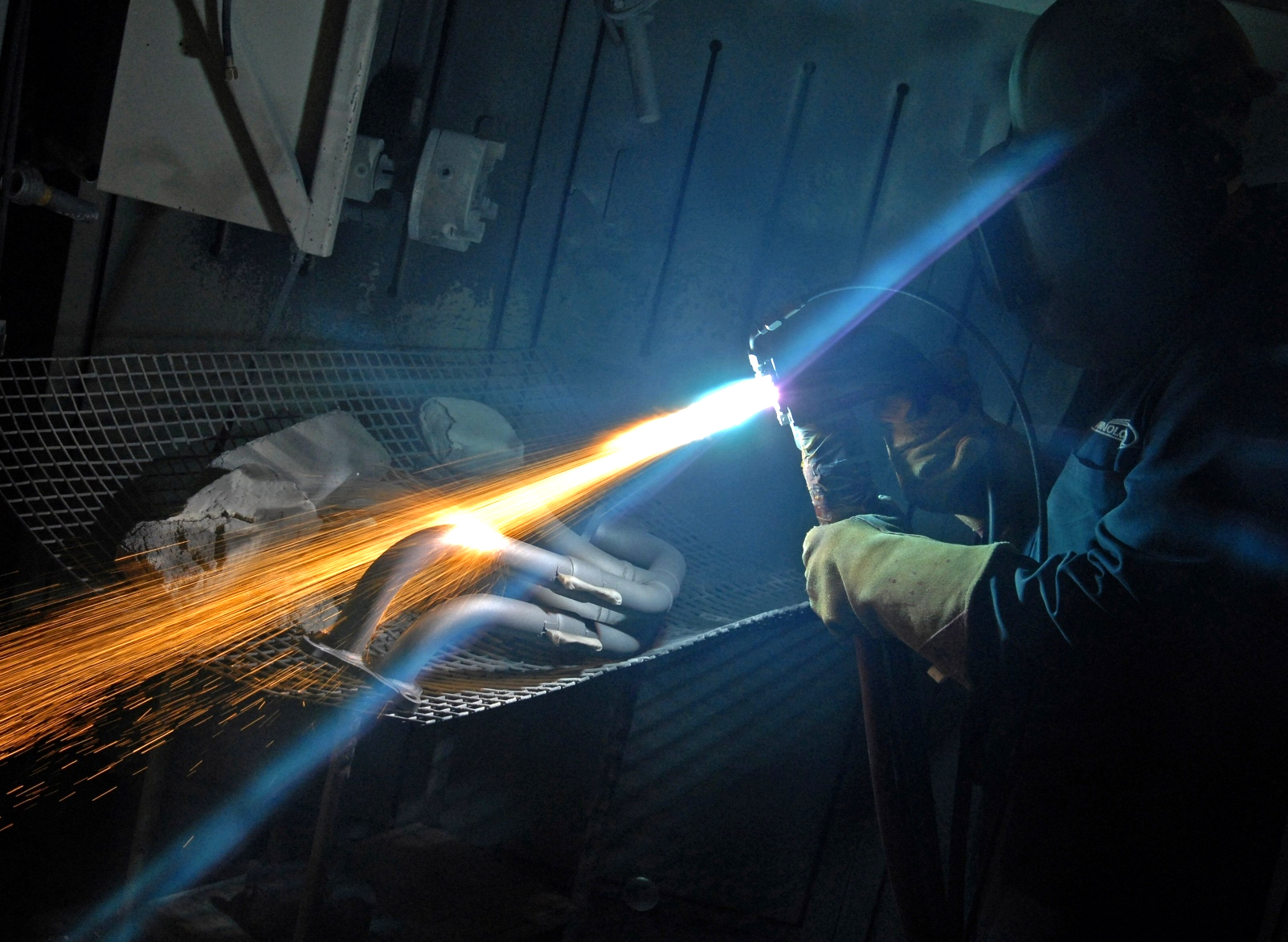
Thermal spraying
View on Wikipedia

Thermal spraying techniques are coating processes in which melted (or heated) materials are sprayed onto a surface. The "feedstock" (coating precursor) is heated by electrical (plasma or arc) or chemical means (combustion flame).
Thermal spraying can provide thick coatings (approx. thickness range is 20 microns to several mm, depending on the process and feedstock), over a large area at high deposition rate as compared to other coating processes such as electroplating, physical and chemical vapor deposition. Coating materials available for thermal spraying include metals, alloys, ceramics, plastics and composites. They are fed in powder or wire form, heated to a molten or semimolten state and accelerated towards substrates in the form of micrometer-size particles. Combustion or electrical arc discharge is usually used as the source of energy for thermal spraying. Resulting coatings are made by the accumulation of numerous sprayed particles. The surface may not heat up significantly, allowing the coating of flammable substances.
Coating quality is usually assessed by measuring its porosity, oxide content, macro and micro-hardness, bond strength and surface roughness. Generally, the coating quality increases with increasing particle velocities.
Variations
[edit]Several variations of thermal spraying are distinguished:
- Plasma spraying
- Detonation spraying
- Wire arc spraying
- Flame spraying
- High velocity oxy-fuel coating spraying (HVOF)
- High velocity air fuel (HVAF)
- Warm spraying
- Cold spraying
- Spray and Fuse
In classical (developed between 1910 and 1920) but still widely used processes such as flame spraying and wire arc spraying, the particle velocities are generally low (< 150 m/s), and raw materials must be molten to be deposited. Plasma spraying, developed in the 1970s, uses a high-temperature plasma jet generated by arc discharge with typical temperatures >15,000 K, which makes it possible to spray refractory materials such as oxides, molybdenum, etc.[1]
System overview
[edit]A typical thermal spray system consists of the following:
- Spray torch (or spray gun) – the core device performing the melting and acceleration of the particles to be deposited
- Feeder – for supplying the powder, wire or liquid to the torch through tubes.
- Media supply – gases or liquids for the generation of the flame or plasma jet, gases for carrying the powder, etc.
- Robot/Labour – for manipulating the torch or the substrates to be coated
- Power supply – often standalone for the torch
- Control console(s) – either integrated or individual for all of the above
Detonation thermal spraying process
[edit]The detonation gun consists of a long water-cooled barrel with inlet valves for gases and powder. Oxygen and fuel (acetylene most common) are fed into the barrel along with a charge of powder. A spark is used to ignite the gas mixture, and the resulting detonation heats and accelerates the powder to supersonic velocity through the barrel. A pulse of nitrogen is used to purge the barrel after each detonation. This process is repeated many times a second. The high kinetic energy of the hot powder particles on impact with the substrate results in a buildup of a very dense and strong coating. The coating adheres through a mechanical bond resulting from the deformation of the base substrate wrapping around the sprayed particles after the high speed impact.
Plasma spraying
[edit]
In plasma spraying process, the material to be deposited (feedstock) — typically as a powder, sometimes as a liquid,[2] suspension[3] or wire — is introduced into the plasma jet, emanating from a plasma torch. In the jet, where the temperature is on the order of 10,000 K, the material is melted and propelled towards a substrate. There, the molten droplets flatten, rapidly solidify and form a deposit. Commonly, the deposits remain adherent to the substrate as coatings; free-standing parts can also be produced by removing the substrate. There are a large number of technological parameters that influence the interaction of the particles with the plasma jet and the substrate and therefore the deposit properties. These parameters include feedstock type, plasma gas composition and flow rate, energy input, torch offset distance, substrate cooling, etc.
Deposit properties
[edit]The deposits consist of a multitude of pancake-like 'splats' called lamellae, formed by flattening of the liquid droplets. As the feedstock powders typically have sizes from micrometers to above 100 micrometers, the lamellae have thickness in the micrometer range and lateral dimension from several to hundreds of micrometers. Between these lamellae, there are small voids, such as pores, cracks and regions of incomplete bonding. As a result of this unique structure, the deposits can have properties significantly different from bulk materials. These are generally mechanical properties, such as lower strength and modulus, higher strain tolerance, and lower thermal and electrical conductivity. Also, due to the rapid solidification, metastable phases can be present in the deposits.
Applications
[edit]This technique is mostly used to produce coatings on structural materials. Such coatings provide protection against high temperatures (for example thermal barrier coatings for exhaust heat management), corrosion, erosion, wear; they can also change the appearance, electrical or tribological properties of the surface, replace worn material, etc. When sprayed on substrates of various shapes and removed, free-standing parts in the form of plates, tubes, shells, etc. can be produced. It can also be used for powder processing (spheroidization, homogenization, modification of chemistry, etc.). In this case, the substrate for deposition is absent and the particles solidify during flight or in a controlled environment (e.g., water). This technique with variation may also be used to create porous structures, suitable for bone ingrowth, as a coating for medical implants. A polymer dispersion aerosol can be injected into the plasma discharge in order to create a grafting of this polymer on to a substrate surface.[3] This application is mainly used to modify the surface chemistry of polymers.
Variations
[edit]Plasma spraying systems can be categorized by several criteria.
Plasma jet generation:
- direct current (DC plasma), where the energy is transferred to the plasma jet by a direct current, high-power electric arc
- induction plasma or RF plasma, where the energy is transferred by induction from a coil around the plasma jet, through which an alternating, radio-frequency current passes
Plasma-forming medium:
- gas-stabilized plasma (GSP), where the plasma forms from a gas; typically argon, hydrogen, helium or their mixtures
- water-stabilized plasma (WSP), where plasma forms from water (through evaporation, dissociation and ionization) or other suitable liquid
- hybrid plasma – with combined gas and liquid stabilization, typically argon and water
Spraying environment:
- atmospheric plasma spraying (APS), performed in ambient air
- controlled atmosphere plasma spraying (CAPS), usually performed in a closed chamber, either filled with inert gas or evacuated
- variations of CAPS: high-pressure plasma spraying (HPPS), low-pressure plasma spraying (LPPS), the extreme case of which is vacuum plasma spraying (VPS, see below)
- underwater plasma spraying
Another variation consists of having a liquid feedstock instead of a solid powder for melting, this technique is known as Solution precursor plasma spray
Vacuum plasma spraying
[edit]
Vacuum plasma spraying (VPS) is a technology for etching and surface modification to create porous layers with high reproducibility and for cleaning and surface engineering of plastics, rubbers and natural fibers as well as for replacing CFCs for cleaning metal components. This surface engineering can improve properties such as frictional behavior, heat resistance, surface electrical conductivity, lubricity, cohesive strength of films, or dielectric constant, or it can make materials hydrophilic or hydrophobic.
The process typically operates at 39–120 °C to avoid thermal damage. It can induce non-thermally activated surface reactions, causing surface changes which cannot occur with molecular chemistries at atmospheric pressure. Plasma processing is done in a controlled environment inside a sealed chamber at a medium vacuum, around 13–65 Pa. The gas or mixture of gases is energized by an electrical field from DC to microwave frequencies, typically 1–500 W at 50 V. The treated components are usually electrically isolated. The volatile plasma by-products are evacuated from the chamber by the vacuum pump, and if necessary can be neutralized in an exhaust scrubber.
In contrast to molecular chemistry, plasmas employ:
- Molecular, atomic, metastable and free radical species for chemical effects.
- Positive ions and electrons for kinetic effects.
Plasma also generates electromagnetic radiation in the form of vacuum UV photons to penetrate bulk polymers to a depth of about 10 μm. This can cause chain scissions and cross-linking.
Plasmas affect materials at an atomic level. Techniques like X-ray photoelectron spectroscopy and scanning electron microscopy are used for surface analysis to identify the processes required and to judge their effects. As a simple indication of surface energy, and hence adhesion or wettability, often a water droplet contact angle test is used. The lower the contact angle, the higher the surface energy and more hydrophilic the material is.
Changing effects with plasma
[edit]At higher energies ionization tends to occur more than chemical dissociations. In a typical reactive gas, 1 in 100 molecules form free radicals whereas only 1 in 106 ionizes. The predominant effect here is the forming of free radicals. Ionic effects can predominate with selection of process parameters and if necessary the use of noble gases.
Wire arc spray
[edit]Wire arc spray is a form of thermal spraying where two consumable metal wires are fed independently into the spray gun. These wires are then charged and an arc is generated between them. The heat from this arc melts the incoming wire, which is then entrained in an air jet from the gun. This entrained molten feedstock is then deposited onto a substrate with the help of compressed air. This process is commonly used for metallic, heavy coatings.[1]
Plasma transferred wire arc
[edit]Plasma transferred wire arc (PTWA) is another form of wire arc spray which deposits a coating on the internal surface of a cylinder, or on the external surface of a part of any geometry. It is predominantly known for its use in coating the cylinder bores of an engine, enabling the use of Aluminum engine blocks without the need for heavy cast iron sleeves. A single conductive wire is used as "feedstock" for the system. A supersonic plasma jet melts the wire, atomizes it and propels it onto the substrate. The plasma jet is formed by a transferred arc between a non-consumable cathode and the type of a wire. After atomization, forced air transports the stream of molten droplets onto the bore wall. The particles flatten when they impinge on the surface of the substrate, due to the high kinetic energy. The particles rapidly solidify upon contact. The stacked particles make up a high wear resistant coating. The PTWA thermal spray process utilizes a single wire as the feedstock material. All conductive wires up to and including 0.0625 in (1.59 mm) can be used as feedstock material, including "cored" wires. PTWA can be used to apply a coating to the wear surface of engine or transmission components to replace a bushing or bearing. For example, using PTWA to coat the bearing surface of a connecting rod offers a number of benefits including reductions in weight, cost, friction potential, and stress in the connecting rod.
High velocity oxygen fuel spraying (HVOF)
[edit]
During the 1980s, a class of thermal spray processes called high velocity oxy-fuel spraying was developed. A mixture of gaseous or liquid fuel and oxygen is fed into a combustion chamber, where they are ignited and combusted continuously. The resultant hot gas at a pressure close to 1 MPa emanates through a converging–diverging nozzle and travels through a straight section. The fuels can be gases (hydrogen, methane, propane, propylene, acetylene, natural gas, etc.) or liquids (kerosene, etc.). The jet velocity at the exit of the barrel (>1000 m/s) exceeds the speed of sound. A powder feed stock is injected into the gas stream, which accelerates the powder up to 800 m/s. The stream of hot gas and powder is directed towards the surface to be coated. The powder partially melts in the stream, and deposits upon the substrate. The resulting coating has low porosity and high bond strength.[1]
HVOF coatings may be as thick as 12 mm (1⁄2 in). It is typically used to deposit wear and corrosion resistant coatings on materials, such as ceramic and metallic layers. Common powders include WC-Co, chromium carbide, MCrAlY, and alumina. The process has been most successful for depositing cermet materials (WC–Co, etc.) and other corrosion-resistant alloys (stainless steels, nickel-based alloys, aluminium, hydroxyapatite for medical implants, etc.).[1]
High Velocity Air Fuel (HVAF)
[edit]HVAF coating technology is the combustion of propane in a compressed air stream. Like HVOF, this produces a uniform high velocity jet. HVAF differs by including a heat baffle to further stabilize the thermal spray mechanisms. Material is injected into the air-fuel stream and coating particles are propelled toward the part.[4] HVAF has a maximum flame temperature of 3,560° to 3,650 °F and an average particle velocity of 3,300 ft/sec. Since the maximum flame temperature is relatively close to the melting point of most spray materials, HVAF results in a more uniform, ductile coating. This also allows for a typical coating thickness of 0.002-0.050". HVAF coatings also have a mechanical bond strength of greater that 12,000 psi. Common HVAF coating materials include, but are not limited to; tungsten carbide, chrome carbide, stainless steel, hastelloy, and inconel. Due to its ductile nature hvaf coatings can help resist cavitation damage.[5]
Spray and Fuse
[edit]Spray and fuse uses high heat to increase the bond between the thermal spray coating and the substrate of the part. Unlike other types of thermal spray, spray and fuse creates a metallurgical bond between the coating and the surface. This means that instead of relying on friction for coating adhesion, it melds the surface and coating material into one material. Spray and fuse comes down to the difference between adhesion and cohesion.
This process usually involves spraying a powdered material onto the component then following with an acetylene torch. The torch melts the coating material and the top layer of the component material; fusing them together. Due to the high heat of spray and fuse, some heat distortion may occur, and care must be taken to determine if a component is a good candidate. These high temperatures are akin to those used in welding. This metallurgical bond creates an extremely wear and abrasion resistant coating. Spray and fuse delivers the benefits of hardface welding with the ease of thermal spray.[6]
Cold spraying
[edit]
Cold spraying (or gas dynamic cold spraying) was introduced to the market in the 1990s. The method was originally developed in the Soviet Union – while experimenting with the erosion of the target substrate, which was exposed to a two-phase high-velocity flow of fine powder in a wind tunnel, scientists observed accidental rapid formation of coatings.[1]
In cold spraying, particles are accelerated to very high speeds by the carrier gas forced through a converging–diverging de Laval type nozzle. Upon impact, solid particles with sufficient kinetic energy deform plastically and bond mechanically to the substrate to form a coating. The critical velocity needed to form bonding depends on the material's properties, powder size and temperature. Metals, polymers, ceramics, composite materials and nanocrystalline powders can be deposited using cold spraying.[7] Soft metals such as Cu and Al are best suited for cold spraying, but coating of other materials (W, Ta, Ti, MCrAlY, WC–Co, etc.) by cold spraying has been reported.[1]
The deposition efficiency is typically low for alloy powders, and the window of process parameters and suitable powder sizes is narrow. To accelerate powders to higher velocity, finer powders (<20 micrometers) are used. It is possible to accelerate powder particles to much higher velocity using a processing gas having high speed of sound (helium instead of nitrogen). However, helium is costly and its flow rate, and thus consumption, is higher. To improve acceleration capability, nitrogen gas is heated up to about 900 °C. As a result, deposition efficiency and tensile strength of deposits increase.[1]
Warm spraying
[edit]Warm spraying is a novel modification of high velocity oxy-fuel spraying, in which the temperature of combustion gas is lowered by mixing nitrogen with the combustion gas, thus bringing the process closer to the cold spraying. The resulting gas contains much water vapor, unreacted hydrocarbons and oxygen, and thus is dirtier than the cold spraying. However, the coating efficiency is higher. On the other hand, lower temperatures of warm spraying reduce melting and chemical reactions of the feed powder, as compared to HVOF. These advantages are especially important for such coating materials as Ti, plastics, and metallic glasses, which rapidly oxidize or deteriorate at high temperatures.[1]
Applications
[edit]
- Crankshaft reconditioning or conditioning
- Corrosion protection
- Fouling protection
- Altering thermal conductivity or electrical conductivity
- Wear control: either hardfacing (wear-resistant) or abradable coating
- Repairing damaged surfaces
- Temperature/oxidation protection (thermal barrier coatings)
- Medical implants coatings (by using polymer derived ceramics)[8]
- Production of functionally graded materials (for any of the above applications)
Limitations
[edit]Thermal spraying is a line of sight process and the bond mechanism is primarily mechanical. Thermal spray application is not compatible with the substrate if the area to which it is applied is complex or blocked by other bodies.[9]
Safety
[edit]Thermal spraying need not be a dangerous process if the equipment is treated with care and correct spraying practices are followed. As with any industrial process, there are a number of hazards of which the operator should be aware and against which specific precautions should be taken. Ideally, equipment should be operated automatically in enclosures specially designed to extract fumes, reduce noise levels, and prevent direct viewing of the spraying head. Such techniques will also produce coatings that are more consistent. There are occasions when the type of components being treated, or their low production levels, require manual equipment operation. Under these conditions, a number of hazards peculiar to thermal spraying are experienced in addition to those commonly encountered in production or processing industries.[10][11]
Noise
[edit]Metal spraying equipment uses compressed gases which create noise. Sound levels vary with the type of spraying equipment, the material being sprayed, and the operating parameters. Typical sound pressure levels are measured at 1 meter behind the arc.[12]
UV light
[edit]Combustion spraying equipment produces an intense flame, which may have a peak temperature more than 3,100 °C and is very bright. Electric arc spraying produces ultra-violet light which may damage delicate body tissues. Plasma also generates quite a lot of UV radiation, easily burning exposed skin and can also cause "flash burn" to the eyes. Spray booths and enclosures should be fitted with ultra-violet absorbent dark glass. Where this is not possible, operators, and others in the vicinity should wear protective goggles containing BS grade 6 green glass. Opaque screens should be placed around spraying areas. The nozzle of an arc pistol should never be viewed directly unless it is certain that no power is available to the equipment.[10]
Dust and fumes
[edit]The atomization of molten materials produces a large amount of dust and fumes made up of very fine particles (ca. 80–95% of the particles by number <100 nm).[13] Proper extraction facilities are vital not only for personal safety, but to minimize entrapment of re-frozen particles in the sprayed coatings. The use of respirators fitted with suitable filters is strongly recommended where equipment cannot be isolated.[13] Certain materials offer specific known hazards:[10]
- Finely divided metal particles are potentially pyrophoric and harmful when accumulated in the body.
- Certain materials e.g. aluminum, zinc and other base metals may react with water to evolve hydrogen. This is potentially explosive and special precautions are necessary in fume extraction equipment.
- Fumes of certain materials, notably zinc and copper alloys, have a disagreeable odour and may cause a fever-type reaction in certain individuals (known as metal fume fever). This may occur some time after spraying and usually subsides rapidly. If it does not, medical advice must be sought.
- Fumes of reactive compounds can dissociate and create harmful gasses. Respirators should be worn in these areas and gas meters should be used to monitor the air before respirators are removed.
Heat
[edit]Combustion spraying guns use oxygen and fuel gases. The fuel gases are potentially explosive. In particular, acetylene may only be used under approved conditions. Oxygen, while not explosive, will sustain combustion and many materials will spontaneously ignite if excessive oxygen levels are present. Care must be taken to avoid leakage and to isolate oxygen and fuel gas supplies when not in use.[10]
Shock hazards
[edit]Electric arc guns operate at low voltages (below 45 V dc), but at relatively high currents. They may be safely hand-held. The power supply units are connected to 440 V AC sources, and must be treated with caution.[10]
See also
[edit]References
[edit]- ^ a b c d e f g h i Kuroda, Seiji; Kawakita, Jin; Watanabe, Makoto; Katanoda, Hiroshi (2008). "Warm spraying—a novel coating process based on high-velocity impact of solid particles". Sci. Technol. Adv. Mater. 9 (3) 033002. doi:10.1088/1468-6996/9/3/033002. PMC 5099653. PMID 27877996.
- ^ Paulussen, S; Rego, R; Goossens, O; Vangeneugden, D; Rose, K (2005). "Plasma polymerization of hybrid organic–inorganic monomers in an atmospheric pressure dielectric barrier discharge". Surface and Coatings Technology. 200 (1–4): 672–675. doi:10.1016/j.surfcoat.2005.02.134.
- ^ a b Leroux, F; Campagne, C; Perwuelz, A; Gengembre, L (2008). "Fluorocarbon nano-coating of polyester fabrics by atmospheric air plasma with aerosol". Applied Surface Science. 254 (13): 3902. Bibcode:2008ApSS..254.3902L. doi:10.1016/j.apsusc.2007.12.037.
- ^ "HVAF Spray | Thermal Spray Coatings | Machine Part Enhancement". HTS Coatings. Retrieved 2020-06-04.
- ^ "Thermal Spray for Pump Cavitation". HTS Coatings. 21 January 2020. Retrieved 2020-06-04.
- ^ "Spray and Fuse Coatings | Fused Coatings | Metallurgically Bonded". HTS Coatings. Retrieved 2020-07-28.
- ^ Moridi, A.; Hassani-Gangaraj, S. M.; Guagliano, M.; Dao, M. (2014). "Cold spray coating: review of material systems and future perspectives". Surface Engineering. 30 (6): 369–395. doi:10.1179/1743294414Y.0000000270. hdl:11311/968457. S2CID 987439.
- ^ Fiocco, L.; Li, S.; Stevens, M. M.; Bernardo, E.; Jones, J. R. (1 March 2017). "Biocompatibility and bioactivity of porous polymer-derived Ca-Mg silicate ceramics". Acta Biomaterialia. 50: 56–67. doi:10.1016/j.actbio.2016.12.043. hdl:10044/1/43928. PMID 28017870.
- ^ Degitz, Todd; Dobler, Klaus (November 2002). "Thermal Spray Basics". Welding Journal. Archived from the original on 2004-11-18.
- ^ a b c d e Blunt, Jane; Balchin, N. C. (2001). Health and safety in welding and allied processes. Woodhead Publishing. pp. 190–205. ISBN 978-1-85573-538-5.
- ^ Kodali, Vamsi; Afshari, Aliakbar; Meighan, Terence; McKinney, Walter; Mazumder, Md Habibul Hasan; Majumder, Nairrita; Cumpston, Jared L.; Leonard, Howard D.; Cumpston, James B.; Friend, Sherri; Leonard, Stephen S.; Erdely, Aaron; Zeidler-Erdely, Patti C.; Hussain, Salik; Lee, Eun Gyung (2022-12-01). "In vivo and in vitro toxicity of a stainless-steel aerosol generated during thermal spray coating". Archives of Toxicology. 96 (12): 3201–3217. Bibcode:2022ArTox..96.3201K. doi:10.1007/s00204-022-03362-7. ISSN 1432-0738. PMID 35984461. S2CID 251671596.
- ^ Suryanarayanan, R. (1993). Plasma Spraying: Theory and Applications. World Scientific Pub Co Inc. p. 211. Bibcode:1993psta.book.....S. ISBN 978-981-02-1363-3.
- ^ a b Bemer, D.; Regnier, R.; Subra, I.; Sutter, B.; Lecler, M. T.; Morele, Y. (2010). "Ultrafine Particles Emitted by Flame and Electric Arc Guns for Thermal Spraying of Metals". Annals of Occupational Hygiene. 54 (6): 607–14. doi:10.1093/annhyg/meq052. PMID 20685717.