

Community hub
Recent from talks
Contribute something
Nothing was collected or created yet.
Resistor
View on Wikipedia
 An array of axial-lead resistors | |
| Component type | Passive |
|---|---|
| Working principle | Electrical resistance |
| Number of terminals | 2 |
| Electronic symbol | |
 ANSI and IEC symbols | |

A resistor is a passive two-terminal electronic component that implements electrical resistance as a circuit element. In electronic circuits, resistors are used to reduce current flow, adjust signal levels, to divide voltages, bias active elements, and terminate transmission lines, among other uses. High-power resistors that can dissipate many watts of electrical power as heat may be used as part of motor controls, in power distribution systems, or as test loads for generators. Fixed resistors have resistances that only change slightly with temperature, time or operating voltage. Variable resistors can be used to adjust circuit elements (such as a volume control or a lamp dimmer), or as sensing devices for heat, light, humidity, force, or chemical activity.
Resistors are common elements of electrical networks and electronic circuits and are ubiquitous in electronic equipment. Practical resistors as discrete components can be composed of various compounds and forms. Resistors are also implemented within integrated circuits.
The electrical function of a resistor is specified by its resistance: common commercial resistors are manufactured over a range of more than nine orders of magnitude. The nominal value of the resistance falls within the manufacturing tolerance, indicated on the component.
Electronic symbols and notation
[edit]Two typical schematic diagram symbols are as follows:
-
 ANSI-style: (a) resistor, (b) rheostat (variable resistor), and (c) potentiometer
 -
 IEC resistor symbol
The notation to state a resistor's value in a circuit diagram varies.
One common scheme is the RKM code following IEC 60062. Rather than using a decimal separator, this notation uses a letter loosely associated with SI prefixes corresponding with the part's resistance. For example, 8K2 as part marking code, in a circuit diagram or in a bill of materials (BOM) indicates a resistor value of 8.2 kΩ. Additional zeros imply a tighter tolerance, for example 15M0 for three significant digits. When the value can be expressed without the need for a prefix (that is, multiplicator 1), an "R" is used instead of the decimal separator. For example, 1R2 indicates 1.2 Ω, and 18R indicates 18 Ω.
Theory of operation
[edit]
Ohm's law
[edit]An ideal resistor (i.e. a resistance without reactance) obeys Ohm's law:

Ohm's law states that the voltage () across a resistor is proportional to the current () passing through it, where the constant of proportionality is the resistance (). For example, if a 300-ohm resistor is attached across the terminals of a 12-volt battery, then a current of 12 / 300 = 0.04 amperes flows through that resistor.


The ohm (symbol: Ω) is the SI unit of electrical resistance, named after Georg Simon Ohm. An ohm is equivalent to a volt per ampere. Since resistors are specified and manufactured over a very large range of values, the derived units of milliohm (1 mΩ = 10−3 Ω), kilohm (1 kΩ = 103 Ω), and megohm (1 MΩ = 106 Ω) are also in common usage.[2][3]: p.20
Series and parallel resistors
[edit]
The total resistance of resistors connected in series is the sum of their individual resistance values.


The total resistance of resistors connected in parallel is the reciprocal of the sum of the reciprocals of the individual resistors.[3]: p.20ff


For example, a 10 ohm resistor connected in parallel with a 5 ohm resistor and a 15 ohm resistor produces 1/1/10 + 1/5 + 1/15 ohms of resistance, or 30/11 = 2.727 ohms.
A resistor network that is a combination of parallel and series connections can be broken up into smaller parts that are either one or the other. Some complex networks of resistors cannot be resolved in this manner, requiring more sophisticated circuit analysis. Generally, the Y-Δ transform, or matrix methods can be used to solve such problems.[4][5][6]
Power dissipation
[edit]At any instant, the power P (watts) consumed by a resistor of resistance R (ohms) is calculated as: where V (volts) is the voltage across the resistor and I (amps) is the current flowing through it. Using Ohm's law, the two other forms can be derived. This power is converted into heat which must be dissipated by the resistor's package before its temperature rises excessively.[3]: p.22

Resistors are rated according to their maximum power dissipation. Discrete resistors in solid-state electronic systems are typically rated as 1⁄10, 1⁄8, or 1⁄4 watt. They usually absorb much less than a watt of electrical power and require little attention to their power rating.

Power resistors are required to dissipate substantial amounts of power and are typically used in power supplies, power conversion circuits, and power amplifiers; this designation is loosely applied to resistors with power ratings of 1 watt or greater. Power resistors are physically larger and may not use the preferred values, color codes, and external packages described below.
If the average power dissipated by a resistor is more than its power rating, damage to the resistor may occur, permanently altering its resistance; this is distinct from the reversible change in resistance due to its temperature coefficient when it warms. Excessive power dissipation may raise the temperature of the resistor to a point where it can burn the circuit board or adjacent components, or even cause a fire. There are flameproof resistors that will not produce flames with any overload of any duration.
Resistors may be specified with higher rated dissipation than is experienced in service to account for poor air circulation, high altitude, or high operating temperature.
All resistors have a maximum voltage rating; this may limit the power dissipation for higher resistance values.[7] For instance, among 1⁄4 watt resistors (a very common sort of leaded resistor) one is listed with a resistance of 100 MΩ[8] and a maximum rated voltage of 750 V. However even placing 750 V across a 100 MΩ resistor continuously would only result in a power dissipation of less than 6 mW, making the nominal 1⁄4 watt rating meaningless.

Nonideal properties
[edit]Practical resistors have a series inductance and a small parallel capacitance; these specifications can be important in high-frequency applications. And while even an ideal resistor inherently has Johnson noise, some resistors have worse noise characteristics and so may be an issue for low-noise amplifiers or other sensitive electronics.
In some precision applications, the temperature coefficient of the resistance may also be of concern.
The unwanted inductance, excess noise, and temperature coefficient are mainly dependent on the technology used in manufacturing the resistor. They are not normally specified individually for a particular family of resistors manufactured using a particular technology.[9] A family of discrete resistors may also be characterized according to its form factor, that is, the size of the device and the position of its leads (or terminals). This is relevant in the practical manufacturing of circuits that may use them.
Practical resistors are also specified as having a maximum power rating which must exceed the anticipated power dissipation of that resistor in a particular circuit: this is mainly of concern in power electronics applications. Resistors with higher power ratings are physically larger and may require heat sinks. In a high-voltage circuit, attention must sometimes be paid to the rated maximum working voltage of the resistor. While there is no minimum working voltage for a given resistor, failure to account for a resistor's maximum rating may cause the resistor to incinerate when current is run through it.
Fixed resistors
[edit]
Lead arrangements
[edit]
Through-hole components typically have "leads" (pronounced /liːdz/) leaving the body "axially", that is, on a line parallel with the part's longest axis. Others have leads coming off their body "radially" instead. Other components may be SMT (surface mount technology), while high power resistors may have one of their leads designed into the heat sink.
Carbon composition
[edit]

Carbon composition resistors (CCR) consist of a solid cylindrical resistive element with embedded wire leads or metal end caps to which the lead wires are attached. The body of the resistor is protected with paint or plastic. Early 20th-century carbon composition resistors had uninsulated bodies; the lead wires were wrapped around the ends of the resistance element rod and soldered. The completed resistor was painted for color-coding of its value.
The resistive element in carbon composition resistors is made from a mixture of finely powdered carbon and an insulating material, usually ceramic. A resin holds the mixture together. The resistance is determined by the ratio of the fill material (the powdered ceramic) to the carbon. Higher concentrations of carbon, which is a good conductor, result in lower resistances. Carbon composition resistors were commonly used in the 1960s and earlier, but are not popular for general use now as other types have better specifications, such as tolerance, voltage dependence, and stress. Carbon composition resistors change value when stressed with over-voltages. Moreover, if internal moisture content, such as from exposure for some length of time to a humid environment, is significant, soldering heat creates a non-reversible change in resistance value. Carbon composition resistors have poor stability with time and were consequently factory sorted to, at best, only 5% tolerance.[10] These resistors are non-inductive, which provides benefits when used in voltage pulse reduction and surge protection applications.[11] Carbon composition resistors have higher capability to withstand overload relative to the component's size.[12]
Carbon composition resistors are still available, but relatively expensive. Values ranged from fractions of an ohm to 22 megohms. Due to their high price, these resistors are no longer used in most applications. However, they are used in power supplies and welding controls.[12] They are also in demand for repair of vintage electronic equipment where authenticity is a factor.
Carbon pile
[edit]A carbon pile resistor is made of a stack of carbon disks compressed between two metal contact plates. Adjusting the clamping pressure changes the resistance between the plates. These resistors are used when an adjustable load is required, such as in testing automotive batteries or radio transmitters. A carbon pile resistor can also be used as a speed control for small motors in household appliances (sewing machines, hand-held mixers) with ratings up to a few hundred watts.[13] A carbon pile resistor can be incorporated in automatic voltage regulators for generators, where the carbon pile controls the field current to maintain relatively constant voltage.[14] This principle is also applied in the carbon microphone.
Carbon film
[edit]
In manufacturing carbon film resistors, a carbon film is deposited on an insulating substrate, and a helix is cut in it to create a long, narrow resistive path. Varying shapes, coupled with the resistivity of amorphous carbon (ranging from 500 to 800 μΩ m), can provide a wide range of resistance values. Carbon film resistors feature lower noise compared to carbon composition resistors because of the precise distribution of the pure graphite without binding.[15] Carbon film resistors feature a power rating range of 0.125 W to 5 W at 70 °C. Resistances available range from 1 ohm to 10 megaohm. The carbon film resistor has an operating temperature range of −55 °C to 155 °C. It has 200 to 600 volts maximum working voltage range. Special carbon film resistors are used in applications requiring high pulse stability.[12]
Printed carbon resistors
[edit]
Carbon composition resistors can be printed directly onto printed circuit board (PCB) substrates as part of the PCB manufacturing process. Although this technique is more common on hybrid PCB modules, it can also be used on standard fibreglass PCBs. Tolerances are typically quite large and can be in the order of 30%. A typical application would be non-critical pull-up resistors.
Thick and thin film
[edit]
Thick film resistors became popular during the 1970s, and most SMD (surface mount device) resistors today are of this type. The resistive element of thick films is 1000 times thicker than thin films,[16] but the principal difference is how the film is applied to the cylinder (axial resistors) or the surface (SMD resistors).
Thin film resistors are made by sputtering (a method of vacuum deposition) the resistive material onto an insulating substrate. The film is then etched in a similar manner to the old (subtractive) process for making printed circuit boards; that is, the surface is coated with a photo-sensitive material, covered by a pattern film, irradiated with ultraviolet light, and then the exposed photo-sensitive coating is developed, and underlying thin film is etched away.
Thick film resistors are manufactured using screen and stencil printing processes.[12]
Because the time during which the sputtering is performed can be controlled, the thickness of the thin film can be accurately controlled. The type of material also varies, consisting of one or more ceramic (cermet) conductors such as tantalum nitride (TaN), ruthenium oxide (RuO
2), lead oxide (PbO), bismuth ruthenate (Bi
2Ru
2O
7), nickel chromium (NiCr), or bismuth iridate (Bi
2Ir
2O
7).
The resistance of both thin and thick film resistors after manufacture is not highly accurate; they are usually trimmed to an accurate value by abrasive or laser trimming. Thin film resistors are usually specified with tolerances of 1% and 5%, and with temperature coefficients of 5 to 50 ppm/K. They also have much lower noise levels, on the level of 10–100 times less than thick film resistors.[17] Thick film resistors may use the same conductive ceramics, but they are mixed with sintered (powdered) glass and a carrier liquid so that the composite can be screen-printed. This composite of glass and conductive ceramic (cermet) material is then fused (baked) in an oven at about 850 °C.
When first manufactured, thick film resistors had tolerances of 5%, but standard tolerances have improved to 2% or 1% in the last few decades.[timeframe?] Temperature coefficients of thick film resistors are typically ±200 or ±250 ppm/K; a 40-kelvin (70 °F) temperature change can change the resistance by 1%.
Thin film resistors are usually far more expensive than thick film resistors. For example, SMD thin film resistors, with 0.5% tolerances and with 25 ppm/K temperature coefficients, when bought in full size reel quantities, are about twice the cost of 1%, 250 ppm/K thick film resistors.
Metal film
[edit]A common type of axial-leaded resistor today is the metal-film resistor. Metal Electrode Leadless Face (MELF) resistors often use the same technology.
Metal film resistors are usually coated with nickel chromium (NiCr), but might be coated with any of the cermet materials listed above for thin film resistors. Unlike thin film resistors, the material may be applied using different techniques than sputtering (though this is one technique used). The resistance value is determined by cutting a helix through the coating rather than by etching, similar to the way carbon resistors are made. The result is a reasonable tolerance (0.5%, 1%, or 2%) and a temperature coefficient that is generally between 50 and 100 ppm/K.[18] Metal film resistors possess good noise characteristics and low non-linearity due to a low voltage coefficient. They are also beneficial due to long-term stability.[12]
Metal oxide film
[edit]Metal-oxide film resistors are made of metal oxides which results in a higher operating temperature and greater stability and reliability than metal film. They are used in applications with high endurance demands.
Wire wound
[edit]

- common
- bifilar
- common on a thin former
- Ayrton–Perry
Wirewound resistors are commonly made by winding a metal wire, usually nichrome, around a ceramic, plastic, or fiberglass core. The ends of the wire are soldered or welded to two caps or rings, attached to the ends of the core. The assembly is protected with a layer of paint, molded plastic, or an enamel coating baked at high temperature. These resistors are designed to withstand unusually high temperatures of up to 450 °C.[12] Wire leads in low power wirewound resistors are usually between 0.6 and 0.8 mm in diameter and tinned for ease of soldering. For higher power wirewound resistors, either a ceramic outer case or an aluminum outer case on top of an insulating layer is used. If the outer case is ceramic, such resistors are sometimes described as "cement" resistors, though they do not actually contain any traditional cement. The aluminum-cased types are designed to be attached to a heat sink to dissipate the heat; the rated power is dependent on being used with a suitable heat sink, e.g., a 50 W power rated resistor overheats at a fraction of the power dissipation if not used with a heat sink. Large wirewound resistors may be rated for 1,000 watts or more.
Because wirewound resistors are coils they have more undesirable inductance than other types of resistor. However, winding the wire in sections with alternately reversed direction can minimize inductance. Other techniques employ bifilar winding, or a flat thin former (to reduce cross-section area of the coil). For the most demanding circuits, resistors with Ayrton–Perry winding are used.
Applications of wirewound resistors are similar to those of composition resistors with the exception of high frequency applications. The high frequency response of wirewound resistors is substantially worse than that of a composition resistor.[12]
Metal foil resistor
[edit]
In 1960, Felix Zandman and Sidney J. Stein[19] presented a development of resistor film of very high stability.
The primary resistance element of a foil resistor is a chromium nickel alloy foil several micrometers thick. Chromium nickel alloys are characterized by having a large electrical resistance (about 58 times that of copper), a small temperature coefficient and high resistance to oxidation. Examples are Chromel A and Nichrome V, whose typical composition is 80 Ni and 20 Cr, with a melting point of 1420 °C. When iron is added, the chromium nickel alloy becomes more ductile. The Nichrome and Chromel C are examples of an alloy containing iron. The composition typical of Nichrome is 60 Ni, 12 Cr, 26 Fe, 2 Mn and Chromel C, 64 Ni, 11 Cr, Fe 25. The melting temperature of these alloys are 1350 °C and 1390 °C, respectively.[20][full citation needed]
Since their introduction in the 1960s, foil resistors have had the best precision and stability of any resistor available. One of the important parameters of stability is the temperature coefficient of resistance (TCR). The TCR of foil resistors is extremely low, and has been further improved over the years. One range of ultra-precision foil resistors offers a TCR of 0.14 ppm/°C, tolerance ±0.005%, long-term stability (1 year) 25 ppm, (3 years) 50 ppm (further improved 5-fold by hermetic sealing), stability under load (2000 hours) 0.03%, thermal EMF 0.1 μV/°C, noise −42 dB, voltage coefficient 0.1 ppm/V, inductance 0.08 μH, capacitance 0.5 pF.[21]
The thermal stability of this type of resistor also has to do with the opposing effects of the metal's electrical resistance increasing with temperature, and being reduced by thermal expansion leading to an increase in thickness of the foil, whose other dimensions are constrained by a ceramic substrate.[citation needed]
Ammeter shunts
[edit]An ammeter shunt is a special type of current-sensing resistor, having four terminals and a value in milliohms or even micro-ohms. Current-measuring instruments, by themselves, can usually accept only limited currents. To measure high currents, the current passes through the shunt across which the voltage drop is measured and interpreted as current. A typical shunt consists of two solid metal blocks, sometimes brass, mounted on an insulating base. Between the blocks, and soldered or brazed to them, are one or more strips of low temperature coefficient of resistance (TCR) manganin alloy. Large bolts threaded into the blocks make the current connections, while much smaller screws provide volt meter connections. Shunts are rated by full-scale current, and often have a voltage drop of 50 mV at rated current. Such meters are adapted to the shunt full current rating by using an appropriately marked dial face; no change need to be made to the other parts of the meter.
Grid resistor
[edit]In heavy-duty industrial high-current applications, a grid resistor is a large convection-cooled lattice of stamped metal alloy strips connected in rows between two electrodes. Such industrial grade resistors can be as large as a refrigerator; some designs can handle over 500 amperes of current, with a range of resistances extending lower than 0.04 ohms. They are used in applications such as dynamic braking and load banking for locomotives and trams, neutral grounding for industrial AC distribution, control loads for cranes and heavy equipment, load testing of generators and harmonic filtering for electric substations.[22]
The term grid resistor is sometimes used to describe a resistor of any type connected to the control grid of a vacuum tube. This is not a resistor technology; it is an electronic circuit topology.
Special varieties
[edit]Variable resistors
[edit]Adjustable resistors
[edit]A resistor may have one or more fixed tapping points so that the resistance can be changed by moving the connecting wires to different terminals. Some wirewound power resistors have a tapping point that can slide along the resistance element, allowing a larger or smaller part of the resistance to be used.
Where continuous adjustment of the resistance value during operation of equipment is required, the sliding resistance tap can be connected to a knob accessible to an operator. Such a device is called a rheostat and has two terminals.
Potentiometers
[edit]
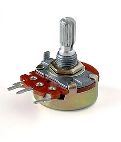
A potentiometer (colloquially, pot) is a three-terminal resistor with a continuously adjustable tapping point controlled by rotation of a shaft or knob or by a linear slider.[23] The name potentiometer comes from its function as an adjustable voltage divider to provide a variable potential at the terminal connected to the tapping point. Volume control in an audio device is a common application of a potentiometer. A typical low power potentiometer (see drawing) is constructed of a flat resistance element (B) of carbon composition, metal film, or conductive plastic, with a springy phosphor bronze wiper contact (C) which moves along the surface. An alternate construction is resistance wire wound on a form, with the wiper sliding axially along the coil.[23] These have lower resolution, since as the wiper moves the resistance changes in steps equal to the resistance of a single turn.[23]
High-resolution multiturn potentiometers are used in precision applications. These have wire-wound resistance elements typically wound on a helical mandrel, with the wiper moving on a helical track as the control is turned, making continuous contact with the wire. Some include a conductive-plastic resistance coating over the wire to improve resolution. These typically offer ten turns of their shafts to cover their full range. They are usually set with dials that include a simple turns counter and a graduated dial, and can typically achieve three-digit resolution. Electronic analog computers used them in quantity for setting coefficients and delayed-sweep oscilloscopes of recent decades included one on their panels.
-
 Typical panel mount potentiometer
 -
 An assortment of small through-hole potentiometers designed for mounting on printed circuit boards.


Resistance decade boxes
[edit].jpg)
A resistance decade box or resistor substitution box is a unit containing resistors of many values, with one or more mechanical switches which allow any one of various discrete resistances offered by the box to be dialed in. Usually the resistance is accurate to high precision, ranging from laboratory/calibration grade accuracy of 20 parts per million, to field grade at 1%. Inexpensive boxes with lesser accuracy are also available. All types offer a convenient way of selecting and quickly changing a resistance in laboratory, experimental and development work without needing to attach resistors one by one, or even stock each value. The range of resistance provided, the maximum resolution, and the accuracy characterize the box. For example, one box offers resistances from 0 to 100 megohms, maximum resolution 0.1 ohm, accuracy 0.1%.[24]
Special devices
[edit]There are various devices whose resistance changes with various quantities. The resistance of NTC thermistors exhibit a strong negative temperature coefficient, making them useful for measuring temperatures. Since their resistance can be large until they are allowed to heat up due to the passage of current, they are also commonly used to prevent excessive current surges when equipment is powered on. Similarly, the resistance of a humistor varies with humidity. One sort of photodetector, the photoresistor, has a resistance which varies with illumination.
The strain gauge, invented by Edward E. Simmons and Arthur C. Ruge in 1938, is a type of resistor that changes value with applied strain. A single resistor may be used, or a pair (half bridge), or four resistors connected in a Wheatstone bridge configuration. The strain resistor is bonded with adhesive to an object that is subjected to mechanical strain. With the strain gauge and a filter, amplifier, and analog/digital converter, the strain on an object can be measured.
A related but more recent invention uses a Quantum Tunnelling Composite to sense mechanical stress. It passes a current whose magnitude can vary by a factor of 1012 in response to changes in applied pressure.
Measurement
[edit]The value of a resistor can be measured with an ohmmeter, which may be one function of a multimeter. Usually, probes on the ends of test leads connect to the resistor. A simple ohmmeter may apply a voltage from a battery across the unknown resistor (with an internal resistor of a known value in series) producing a current which drives a meter movement. The current, in accordance with Ohm's law, is inversely proportional to the sum of the internal resistance and the resistor being tested, resulting in an analog meter scale which is very non-linear, calibrated from infinity to 0 ohms. A digital multimeter, using active electronics, may instead pass a specified current through the test resistance. The voltage generated across the test resistance in that case is linearly proportional to its resistance, which is measured and displayed. In either case the low-resistance ranges of the meter pass much more current through the test leads than do high-resistance ranges. This allows for the voltages present to be at reasonable levels (generally below 10 volts) but still measurable.
Measuring low-value resistors, such as fractional-ohm resistors, with acceptable accuracy requires four-terminal connections. One pair of terminals applies a known, calibrated current to the resistor, while the other pair senses the voltage drop across the resistor. Some laboratory quality ohmmeters, milliohmmeters, and even some of the better digital multimeters sense using four input terminals for this purpose, which may be used with special test leads called Kelvin clips. Each of the two clips has a pair of jaws insulated from each other. One side of each clip applies the measuring current, while the other connections are only to sense the voltage drop. The resistance is again calculated using Ohm's Law as the measured voltage divided by the applied current.
Standards
[edit]Production resistors
[edit]Resistor characteristics are quantified and reported using various national standards. In the US, MIL-STD-202[25] contains the relevant test methods to which other standards refer.
There are various standards specifying properties of resistors for use in equipment:
- IEC 60062 (IEC 62) / DIN 40825 / BS 1852 / IS 8186 / JIS C 5062 etc. (Resistor color code, RKM code, date code)
- EIA RS-279 / DIN 41429 (Resistor color code)
- IEC 60063 (IEC 63) / JIS C 5063 (Standard E series values)
- MIL-PRF-26
- MIL-PRF-39007 (Fixed power, established reliability)
- MIL-PRF-55342 (Surface-mount thick and thin film)
- MIL-PRF-914
- MIL-R-11 Standard Canceled
- MIL-R-39017 (Fixed, General Purpose, Established Reliability)
- MIL-PRF-32159 (zero ohm jumpers)
- UL 1412 (fusing and temperature limited resistors)[26]
There are other United States military procurement MIL-R- standards.
Resistance standards
[edit]The primary standard for resistance, the "mercury ohm" was initially defined in 1884 in as a column of mercury 106.3 cm long and 1 square millimeter in cross-section, at 0 degrees Celsius. Difficulties in precisely measuring the physical constants to replicate this standard result in variations of as much as 30 ppm. From 1900 the mercury ohm was replaced with a precision machined plate of manganin.[27] Since 1990 the international resistance standard has been based on the quantized Hall effect discovered by Klaus von Klitzing, for which he won the Nobel Prize in Physics in 1985.[28]
Resistors of extremely high precision are manufactured for calibration and laboratory use. They may have four terminals, using one pair to carry an operating current and the other pair to measure the voltage drop; this eliminates errors caused by voltage drops across the lead resistances, because no charge flows through voltage sensing leads. It is important in small value resistors (100–0.0001 ohm) where lead resistance is significant or even comparable with respect to resistance standard value.[29]
Resistor marking
[edit]
Axial resistor cases are usually tan, brown, blue, or green (though other colors are occasionally found as well, such as dark red or dark gray), and display three to six colored stripes that indicate resistance (and by extension tolerance), and may include bands to indicate the temperature coefficient and reliability class. In four-striped resistors, the first two stripes represent the first two digits of the resistance in ohms, the third represents a multiplier, and the fourth the tolerance (which if absent, denotes ±20%). For five- and six- striped resistors the third band is the third digit, the fourth is the multiplier and the fifth is the tolerance; a sixth stripe represents the temperature coefficient. The power rating of the resistor is usually not marked and is deduced from its size.
Surface-mount resistors are marked numerically.
Early 20th century resistors, essentially uninsulated, were dipped in paint to cover their entire body for color-coding. This base color represented the first digit. A second color of paint was applied to one end of the element to represent a second digit, and a color dot (or band) in the middle provided the third digit. The rule was "body, tip, dot", providing two significant digits for value and the decimal multiplier, in that sequence. Default tolerance was ±20%. Closer-tolerance resistors had silver (±10%) or gold-colored (±5%) paint on the other end.
Preferred values
[edit]Early resistors were made in more or less arbitrary round numbers; a series might have 100, 125, 150, 200, 300, etc.[30] Early power wirewound resistors, such as brown vitreous-enameled types, were made with a system of preferred values like some of those mentioned here. Resistors as manufactured are subject to a certain percentage tolerance, and it makes sense to manufacture values that correlate with the tolerance, so that the actual value of a resistor overlaps slightly with its neighbors. Wider spacing leaves gaps; narrower spacing increases manufacturing and inventory costs to provide resistors that are more or less interchangeable.
A logical scheme is to produce resistors in a range of values which increase in a geometric progression, so that each value is greater than its predecessor by a fixed multiplier or percentage, chosen to match the tolerance of the range. For example, for a tolerance of ±20% it makes sense to have each resistor about 1.5 times its predecessor, covering a decade in 6 values. More precisely, the factor used is 1.4678 ≈ , giving values of 1.47, 2.15, 3.16, 4.64, 6.81, 10 for the 1–10-decade (a decade is a range increasing by a factor of 10; 0.1–1 and 10–100 are other examples); these are rounded in practice to 1.5, 2.2, 3.3, 4.7, 6.8, 10; followed by 15, 22, 33, ... and preceded by ... 0.47, 0.68, 1. This scheme has been adopted as the E6 series of the IEC 60063 preferred number values. There are also E12, E24, E48, E96 and E192 series for components of progressively finer resolution, with 12, 24, 48, 96, and 192 different values within each decade. The actual values used are in the IEC 60063 lists of preferred numbers.

A resistor of 100 ohms ±20% would be expected to have a value between 80 and 120 ohms; its E6 neighbors are 68 (54–82) and 150 (120–180) ohms. A sensible spacing, E6 is used for ±20% components; E12 for ±10%; E24 for ±5%; E48 for ±2%, E96 for ±1%; E192 for ±0.5% or better. Resistors are manufactured in values from a few milliohms to about a gigaohm in IEC60063 ranges appropriate for their tolerance. Manufacturers may sort resistors into tolerance-classes based on measurement. Accordingly, a selection of 100 ohms resistors with a tolerance of ±10%, might not lie just around 100 ohm (but no more than 10% off) as one would expect (a bell-curve), but rather be in two groups – either between 5 and 10% too high or 5 to 10% too low (but not closer to 100 ohm than that) because any resistors the factory had measured as being less than 5% off would have been marked and sold as resistors with only ±5% tolerance or better. When designing a circuit, this may become a consideration. This process of sorting parts based on post-production measurement is known as "binning", and can be applied to other components than resistors (such as speed grades for CPUs).
SMT resistors
[edit]
Surface mounted resistors of larger sizes (metric 1608 and above) are printed with numerical values in a code related to that used on axial resistors. Standard-tolerance surface-mount technology (SMT) resistors are marked with a three-digit code, in which the first two digits are the first two significant digits of the value and the third digit is the power of ten (the number of zeroes). For example:
- 334 = 33 × 104 Ω = 330 kΩ
- 222 = 22 × 102 Ω = 2.2 kΩ
- 473 = 47 × 103 Ω = 47 kΩ
- 105 = 10 × 105 Ω = 1 MΩ
Resistances less than 100 Ω are written: 100, 220, 470. The final zero represents ten to the power zero, which is 1. For example:
- 100 = 10 × 100 Ω = 10 Ω
- 220 = 22 × 100 Ω = 22 Ω
Sometimes these values are marked as 10 or 22 to prevent a mistake.
Resistances less than 10 Ω have 'R' to indicate the position of the decimal point (radix point). For example:
- 4R7 = 4.7 Ω
- R300 = 0.30 Ω
- 0R22 = 0.22 Ω
- 0R01 = 0.01 Ω
000 and 0000 sometimes appear as values on surface-mount zero-ohm links, since these have (approximately) zero resistance.
More recent surface-mount resistors are too small, physically, to permit practical markings to be applied.
Precision resistor markings
[edit]Many precision resistors, including surface mount and axial-lead types, are marked with a four-digit code. The first three digits are the significant figures and the fourth is the power of ten. For example:
- 1001 = 100 × 101 Ω = 1.00 kΩ
- 4992 = 499 × 102 Ω = 49.9 kΩ
- 1000 = 100 × 100 Ω = 100 Ω
Axial-lead precision resistors often use color code bands to represent this four-digit code.
EIA-96 marking
[edit]The former EIA-96 marking system now included in IEC 60062:2016 is a more compact marking system intended for physically small high-precision resistors. It uses a two-digit code plus a letter (a total of three alphanumeric characters) to indicate 1% resistance values to three significant digits.[31] The two digits (from "01" to "96") are a code that indicates one of the 96 "positions" in the standard E96 series of 1% resistor values. The uppercase letter is a code that indicates a power of ten multiplier. For example, the marking "01C" represents 10 kOhm; "10C" represents 12.4 kOhm; "96C" represents 97.6 kOhm.[32][33][34][35][36]
|
| ||||||||||||||||||||||||||||||||||||||||||||||||||||||||||||||||||||||||||||||||||||||||||||||||||||||||||||||||||||||||||||||||||||||||||||||||||||||||||||||||||||||||||||||||||||||||||||||||||||||||||||||||||||||||||||||||||||||||||||||||||||||||||||||||||||||||||||||||||||||||||||||||||||||||||||||||||||||||||||||||||||||||||||||||||||||||||||||||||||||||||||||||||||||||||||||||||||||||||||||||||||||||||||||||||||||||||||||||||||||||||||||||||||||||||||||||||||||||||||||||||||||||||||||||||||||||||||||||||||||||||||||||||||||||||||||||||||||||||||||||||||||||||||||||||||||||||||||||||||||||||||||||||||||||||||||||||||||||||||||||||||||||||||||||||||||||||||||||||||||||||||||||||||||||||||||||||||||||||||||||||||||||||||||||||||||||||||||||||||||||||||||||||||||||||||||||||||||||||||||||||||||||||||||||||||||||||||||||||||||||||||||||||||||||||||||||||||||||||||||||||||||||||||||||||||
Industrial type designation
[edit]| Type no. | Power rating (watts) |
MIL-R-11 style |
MIL-R-39008 style |
|---|---|---|---|
| BB | 1⁄8 | RC05 | RCR05 |
| CB | 1⁄4 | RC07 | RCR07 |
| EB | 1⁄2 | RC20 | RCR20 |
| GB | 1 | RC32 | RCR32 |
| HB | 2 | RC42 | RCR42 |
| GM | 3 | - | - |
| HM | 4 | - | - |
| Industrial type designation | Tolerance | MIL designation |
|---|---|---|
| 5 | ±5% | J |
| 2 | ±20% | M |
| 1 | ±10% | K |
| - | ±2% | G |
| - | ±1% | F |
| - | ±0.5% | D |
| - | ±0.25% | C |
| - | ±0.1% | B |
Steps to find out the resistance or capacitance values:[37]
- First two letters gives the power dissipation capacity.
- Next three digits gives the resistance value.
- First two digits are the significant values
- Third digit is the multiplier.
- Final digit gives the tolerance.
If a resistor is coded:
- EB1041: power dissipation capacity = 1/2 watts, resistance value = 10×104±10% = between 9×10⁴ ohms and 11×104 ohms.
- CB3932: power dissipation capacity = 1/4 watts, resistance value = 39×103±20% = between 31.2×10³ and 46.8×10³ ohms.
Common usage patterns
[edit]There are several common usage patterns that resistors are commonly configured in.[38]
Current limiting
[edit]Resistors are commonly used to limit the amount of current flowing through a circuit. Many circuit components (such as LEDs) require the current flowing through them to be limited, but do not themselves limit the amount of current. Therefore, oftentimes resistors will be added to prevent overcurrent situations. Additionally, oftentimes circuits do not need the amount of current that would be otherwise flowing through them, so resistors can be added to limit the power consumption of such circuits.
Voltage divider
[edit]Oftentimes circuits need to provide various reference voltages for other circuits (such as voltage comparators). A fixed voltage can be obtained by taking two resistors in series between two other fixed voltages (such as the source voltage and ground). The terminal between the two resistors will be at a voltage that is between the two voltages, at a linear distance based on the relative resistances of the two resistors. For instance, if a 200 ohm resistor and a 400 ohm resistor are placed in series between 6 V and 0 V, the terminal between them will be at 4 V.
Pull-down and pull-up resistors
[edit]When a circuit is not connected to power, the voltage of that circuit is not zero but undefined (it can be influenced by previous voltages or the environment). A pull-up or pull-down resistor provides a voltage for a circuit when it is otherwise disconnected (such as when a button is not pushed down or a transistor is not active). A pull-up resistor connects the circuit to a high positive voltage (if the circuit requires a high positive default voltage) and a pull-down resistor connects the circuit to a low voltage or ground (if the circuit requires a low default voltage). The resistor value must be high enough so that, when the circuit is active, the voltage source it is attached to does not over influence the function of the circuit, but low enough so that it "pulls" quickly enough when the circuit is deactivated, and does not significantly alter the voltage from the source value.
Electrical and thermal noise
[edit]In amplifying faint signals, it is often necessary to minimize electronic noise, particularly in the first stage of amplification. As a dissipative element, even an ideal resistor naturally produces a randomly fluctuating voltage, or noise, across its terminals. This Johnson–Nyquist noise is a fundamental noise source which depends only upon the temperature and resistance of the resistor, and is predicted by the fluctuation–dissipation theorem. Using a larger value of resistance produces a larger voltage noise, whereas a smaller value of resistance generates more current noise, at a given temperature.
The thermal noise of a practical resistor may also be larger than the theoretical prediction and that increase is typically frequency-dependent. Excess noise of a practical resistor is observed only when current flows through it. This is specified in unit of μV/V/decade – μV of noise per volt applied across the resistor per decade of frequency. The μV/V/decade value is frequently given in dB so that a resistor with a noise index of 0 dB exhibits 1 μV (rms) of excess noise for each volt across the resistor in each frequency decade. Excess noise is thus an example of 1/f noise. Thick-film and carbon composition resistors generate more excess noise than other types at low frequencies. Wire-wound and thin-film resistors are often used for their better noise characteristics. Carbon composition resistors can exhibit a noise index of 0 dB while bulk metal foil resistors may have a noise index of −40 dB, usually making the excess noise of metal foil resistors insignificant.[39] Thin film surface mount resistors typically have lower noise and better thermal stability than thick film surface mount resistors. Excess noise is also size-dependent: in general, excess noise is reduced as the physical size of a resistor is increased (or multiple resistors are used in parallel), as the independently fluctuating resistances of smaller components tend to average out.
While not an example of "noise" per se, a resistor may act as a thermocouple, producing a small DC voltage differential across it due to the thermoelectric effect if its ends are at different temperatures. This induced DC voltage can degrade the precision of instrumentation amplifiers in particular. Such voltages appear in the junctions of the resistor leads with the circuit board and with the resistor body. Common metal film resistors show such an effect at a magnitude of about 20 μV/°C. Some carbon composition resistors can exhibit thermoelectric offsets as high as 400 μV/°C, whereas specially constructed resistors can reduce this number to 0.05 μV/°C. In applications where the thermoelectric effect may become important, care has to be taken to mount the resistors horizontally to avoid temperature gradients and to mind the air flow over the board.[40]
Failure modes
[edit]The failure rate of resistors in a properly designed circuit is low compared to other electronic components such as semiconductors and electrolytic capacitors. Damage to resistors most often occurs due to overheating when the average power delivered to it greatly exceeds its ability to dissipate heat (specified by the resistor's power rating). This may be due to a fault external to the circuit but is frequently caused by the failure of another component (such as a transistor that shorts out) in the circuit connected to the resistor. Operating a resistor too close to its power rating can limit the resistor's lifespan or cause a significant change in its resistance. A safe design generally uses overrated resistors in power applications to avoid this danger.
Low-power thin-film resistors can be damaged by long-term high-voltage stress, even below maximum specified voltage and below maximum power rating. This is often the case for the startup resistors feeding a switched-mode power supply integrated circuit.[citation needed]
When overheated, carbon-film resistors may decrease or increase in resistance.[41] Carbon film and composition resistors can fail (open circuit) if running close to their maximum dissipation. This is also possible but less likely with metal film and wirewound resistors.
There can also be failure of resistors due to mechanical stress and adverse environmental factors including humidity. If not enclosed, wirewound resistors can corrode.
Surface mount resistors have been known to fail due to the ingress of sulfur into the internal makeup of the resistor. This sulfur chemically reacts with the silver layer to produce non-conductive silver sulfide. The resistor's impedance goes to infinity. Sulfur resistant and anti-corrosive resistors are sold into automotive, industrial, and military applications. ASTM B809 is an industry standard that tests a part's susceptibility to sulfur.
An alternative failure mode can be encountered where large value resistors are used (hundreds of kilohms and higher). Resistors are not only specified with a maximum power dissipation, but also for a maximum voltage drop. Exceeding this voltage causes the resistor to degrade slowly reducing in resistance. The voltage dropped across large value resistors can be exceeded before the power dissipation reaches its limiting value. Since the maximum voltage specified for commonly encountered resistors is a few hundred volts, this is a problem only in applications where these voltages are encountered.
Variable resistors can also degrade in a different manner, typically involving poor contact between the wiper and the body of the resistance. This may be due to dirt or corrosion and is typically perceived as "crackling" as the contact resistance fluctuates; this is especially noticed as the device is adjusted. This is similar to crackling caused by poor contact in switches, and like switches, potentiometers are to some extent self-cleaning: running the wiper across the resistance may improve the contact. Potentiometers which are seldom adjusted, especially in dirty or harsh environments, are most likely to develop this problem. When self-cleaning of the contact is insufficient, improvement can usually be obtained through the use of contact cleaner (also known as "tuner cleaner") spray. The crackling noise associated with turning the shaft of a dirty potentiometer in an audio circuit (such as the volume control) is greatly accentuated when an undesired DC voltage is present, often indicating the failure of a DC blocking capacitor in the circuit.
See also
[edit]References
[edit]- ^ Harder, Douglas Wilhelm. "Resistors: A Motor with a Constant Force (Force Source)". Department of Electrical and Computer Engineering, University of Waterloo. Retrieved 9 November 2014.
- ^ American Radio Relay League (ARRL) (2021). "Fundamental Theory—Circuits and Components". ARRL Handbook for Radio Communications (98 ed.). American Radio Relay League. ISBN 978-1-62595-139-7.
- ^ a b c Doug DeMaw, ed. (1968). "Electrical Laws and Circuits —Resistance". Radio Amateurs Handbook (45 ed.). American Radio Relay League.
- ^ Farago, P.S. (1961) An Introduction to Linear Network Analysis, pp. 18–21, The English Universities Press Ltd.
- ^ Wu, F. Y. (2004). "Theory of resistor networks: The two-point resistance". Journal of Physics A: Mathematical and General. 37 (26): 6653–6673. arXiv:math-ph/0402038. Bibcode:2004JPhA...37.6653W. doi:10.1088/0305-4470/37/26/004. S2CID 119611570.
- ^ Wu, Fa Yueh; Yang, Chen Ning (2009). Exactly Solved Models: A Journey in Statistical Mechanics : Selected Papers with Commentaries (1963–2008). World Scientific. pp. 489–. ISBN 978-981-281-388-6.
- ^ "Specifications and How to Interpret Them" (PDF). Stackpole Electronics. Retrieved July 6, 2021.
- ^ "Through Hole Resistor, 0.1 Gohm, RGP Series, 250 mW, ± 5%, Axial Leaded, 750 V". nl.farnell.com. Archived from the original on 2021-07-09. Retrieved 2023-10-07.
- ^ A family of resistors may also be characterized according to its critical resistance. Applying a constant voltage across resistors in that family below the critical resistance will exceed the maximum power rating first; resistances larger than the critical resistance fail first from exceeding the maximum voltage rating. See Middleton, Wendy; Van Valkenburg, Mac E. (2002). Reference data for engineers: radio, electronics, computer, and communications (9 ed.). Newnes. pp. 5–10. ISBN 0-7506-7291-9.
- ^ Harter, James H. and Lin, Paul Y. (1982) Essentials of electric circuits. Reston Publishing Company. pp. 96–97. ISBN 0-8359-1767-3.
- ^ HVR International (ed.). "SR Series: Surge Resistors for PCB Mounting". (PDF; 252 kB), 26 May 2005, retrieved 24 January 2017.
- ^ a b c d e f g Beyschlag, Vishay (2008). "Basics of Linear Fixed Resistors Application Note", Document Number 28771.
- ^ Morris, C. G. (ed.) (1992). Academic Press Dictionary of Science and Technology. Gulf Professional Publishing. p. 360. ISBN 0122004000.
- ^ Principles of automotive vehicles. United States Department of the Army (1985). p. 13
- ^ "Carbon Film Resistor". The Resistorguide. Retrieved 10 March 2013.
- ^ "Thick Film and Thin Film" (PDF). Digi-Key (SEI). Archived from the original (PDF) on 27 September 2011. Retrieved 23 July 2011.
- ^ "Thin and Thick film". resistorguide.com. resistor guide. Retrieved 3 December 2017.
- ^ Kuhn, Kenneth A. "Measuring the Temperature Coefficient of a Resistor" (PDF). Archived from the original (PDF) on 2016-03-04. Retrieved 2010-03-18.
- ^ Zandman, F.; Stein, S. (1964). "A New Precision Film Resistor Exhibiting Bulk Properties". IEEE Transactions on Component Parts. 11 (2): 107–119. doi:10.1109/TCP.1964.1135008.
- ^ Procedures in Experimental Physics, John Strong, p. 546.
- ^ "Alpha Electronics Corp. Metal Foil Resistors". Alpha-elec.co.jp. Retrieved 2008-09-22.
- ^ "Grid Resistors: High Power/High Current". Milwaukee Resistor Corporation. Retrieved 14 May 2012.
- ^ a b c Mazda, F. F. (1981). Discrete Electronic Components. CUP Archive. pp. 57–61. ISBN 0521234700.
- ^ "Decade Box – Resistance Decade Boxes". Ietlabs.com. Retrieved 2008-09-22.
- ^ "Test method standard: electronic and electrical component parts" (PDF). Department of Defense. Archived from the original (PDF) on 2015-02-09.
- ^ Fusing Resistors and Temperature-Limited Resistors for Radio- and Television- Type Appliances UL 1412. ulstandardsinfonet.ul.com
- ^ Stability of Double-Walled Manganin Resistors Archived 2006-10-06 at the Wayback Machine. NIST.gov
- ^ Klaus von Klitzing The Quantized Hall Effect. Nobel lecture, December 9, 1985. nobelprize.org
- ^ "Standard Resistance Unit Type 4737B". Tinsley.co.uk. Archived from the original on 2008-08-21. Retrieved 2008-09-22.
- ^ "1940 Catalog – page 60 – Resistors". RadioShack. Archived from the original on 11 July 2017. Retrieved 11 July 2017.
- ^ "Chapter 2 - Resistor standards and codes".
- ^ "CRP0603 Series - Precision Chip Resistors". p. 3.
- ^ "Online calculator - EIA-96 SMD resistor".
- ^ "SMD Resistor Codes: How to Find the Value of SMD Resistors".
- ^ "Marking Codes used on Welwyn Chip Resistors". p. 2.
- ^ "Surface Mount Resistor: codes & markings".
- ^ Maini, A. K. (2008), Electronics and Communications Simplified, 9th ed., Khanna Publications. ISBN 817409217X
- ^ Bartlett, Jonathan (2020). "Basic Resistor Circuit Patterns". Electronics for Beginners. pp. 129–144. doi:10.1007/978-1-4842-5979-5_9. ISBN 978-1-4842-5978-8. S2CID 226539488.
- ^ Audio Noise Reduction Through the Use of Bulk Metal Foil Resistors – "Hear the Difference" (PDF). Archived from the original (PDF) on 2013-01-19. Retrieved 2009-08-03., Application note AN0003, Vishay Intertechnology Inc, 12 July 2005.
- ^ Jung, Walt (2005). "Chapter 7 – Hardware and Housekeeping Techniques" (PDF). Op Amp Applications Handbook. Newnes. p. 7.11. ISBN 0-7506-7844-5.
- ^ "Electronic components – resistors". Inspector's Technical Guide. US Food and Drug Administration. 1978-01-16. Archived from the original on 2008-04-03. Retrieved 2008-06-11.
External links
[edit]- Color Coded Resistance Calculator - University of Pennsylvania
- Resistor Types – Does It Matter? - Aiken Amps
- Difference between types of resistors - Analog Devices
- Basics of Linear Fixed Resistors - Vishay
- 4-terminal resistors – How ultra-precise resistors work - PSL
- Beginners' Guide to Potentiometers - ESP
| International | |
|---|---|
| National | |
| Other | |
Resistor
View on GrokipediaBasic Principles
Definition and Role
A resistor is a passive two-terminal electrical component that implements electrical resistance as a circuit element by opposing the flow of electric current and dissipating the resulting energy primarily as heat.[5][6] Unlike active components such as transistors, resistors do not generate or amplify signals but instead provide a controlled opposition to current, making them essential for managing electrical behavior in circuits. The concept of electrical resistance originated from the work of German physicist Georg Simon Ohm, who formalized it in 1827 through his discovery of the proportional relationship between voltage, current, and resistance, later known as Ohm's law.[7] Modern fixed resistors emerged in the early 20th century with advancements in materials like carbon composition, enabling standardized production for widespread use in electronics.[8] At its core, the resistance of a material arises from its intrinsic properties, including resistivity (), the length () of the conductor, and its cross-sectional area (), expressed by the formulaThis equation demonstrates how resistance increases with length and resistivity while decreasing with greater cross-sectional area, reflecting the physical hindrance to electron flow within the material.[9] The unit of resistance is the ohm (), defined as the resistance that allows one ampere of current to flow under one volt of potential difference; common prefixes include kilo-ohm (k, ) and mega-ohm (M, ).[10] In electrical circuits, resistors serve critical roles such as limiting current to protect components, dividing voltages to create reference levels, and setting bias points for active devices like transistors to ensure stable operation.[11] By precisely controlling current and voltage, they enable the design of reliable analog and digital systems, from simple voltage regulators to complex signal processing networks.[12]
Symbols and Notation
In electrical schematics, the International Electrotechnical Commission (IEC) standard 60617 defines the graphical symbol for a fixed resistor as a rectangle.[13] For variable resistors, the IEC symbol is a rectangle with an arrow indicating the wiper position.[14] The American National Standards Institute (ANSI) and Institute of Electrical and Electronics Engineers (IEEE) standards, such as ANSI Y32.2 and IEEE 315, use a zigzag line for the fixed resistor.[15] Variable resistors under this standard feature an arrow indicating the wiper on the zigzag symbol.[13] Resistor values in circuit diagrams follow standardized notation conventions, typically labeled with "R" followed by a numeric identifier (e.g., R1 for the first resistor) and the resistance value in ohms (Ω), often using multipliers like k (kilo) or M (mega) for brevity, such as R1 = 10 kΩ.[11] Physical components may also employ color codes to indicate values, though these are interpreted separately from schematic notation and detailed in component marking standards.[16] Standard resistors lack polarity indicators in their symbols, as they are bidirectional components without preferred current direction; the rectangle or zigzag symbols show no + or - markings.[17] Certain specialized variants, such as negative temperature coefficient (NTC) thermistors, may include brief schematic notes on orientation for measurement purposes, distinguishing them from non-polarized fixed resistors.[18] In schematic diagrams, resistor symbols are placed to illustrate series or parallel configurations without regard to orientation, as the non-directional nature of resistors means current flow is unaffected by symbol rotation; for instance, in a series connection, symbols align end-to-end, while parallel arrangements show branches converging at nodes.[19]Electrical Theory
Ohm's Law
Ohm's law states that the electric current through a conductor between two points is directly proportional to the voltage across the two points and inversely proportional to the resistance between them, expressed as , where is in volts (V), is in amperes (A), and is in ohms ().[20][21] This relationship derives from fundamental principles in conductors, assuming uniform current density and a constant electric field. The current density (current per unit cross-sectional area) is proportional to the electric field , given by , where is the material's conductivity (the reciprocal of resistivity , so ). For a conductor of length and uniform cross-sectional area , the total current , and the voltage . Substituting yields , defining resistance as , thus . This assumes ohmic materials where the proportionality holds linearly under uniform conditions.[22][23] For example, applying 5 V across a 1 k resistor (1000 ) yields a current of A, or 5 mA. Conversely, if 2 A flows through a resistor under 10 V, the resistance is .[24][20] Ohm's law applies specifically to ohmic or linear resistors, where the current-voltage relationship is linear, resulting in constant resistance independent of applied voltage. Non-ohmic devices, such as diodes, exhibit nonlinear behavior where resistance varies with voltage.[25][26] This law forms the foundational basis for all subsequent resistance calculations in electrical circuits.[20]Series and Parallel Networks
In electrical circuits, resistors connected in series share the same current, leading to an equivalent resistance that is the sum of the individual resistances. For resistors in series with resistances , the total resistance is given by .[27] This result follows from Kirchhoff's voltage law (KVL), which states that the sum of voltage drops around a closed loop is zero; since the current is identical through each resistor, the total voltage implies the voltages add as , yielding the summation formula.[28] The voltage across each resistor divides proportionally to its resistance value, such that for the -th resistor. For example, two 100 Ω resistors in series yield an equivalent resistance of 200 Ω.[29] Resistors in parallel, by contrast, share the same voltage across their terminals, resulting in an equivalent resistance derived from the reciprocal sum of the individual conductances. For resistors in parallel, the total conductance satisfies , or equivalently .[27] This arises from Kirchhoff's current law (KCL), which requires that the sum of currents entering a junction equals the sum leaving; with identical voltage across each, the total current becomes , confirming the reciprocal formula.[28] The current through each resistor divides inversely proportional to its resistance, so . As an illustration, two 100 Ω resistors in parallel produce an equivalent resistance of 50 Ω.[29] For more complex resistor networks that cannot be simplified solely through series and parallel combinations, transformations such as the delta-Y (Δ-Y) conversion are employed to rearrange the topology into equivalent forms amenable to reduction. In a delta configuration with resistors , , and , the equivalent wye resistors are , , and ; the reverse wye-to-delta formulas follow similarly by solving for the delta branches.[30] These transformations preserve the equivalent resistance between any two terminals and are derived by equating the terminal behaviors under KVL and KCL.[31] In general resistor networks with arbitrary interconnections, full analysis requires advanced techniques like mesh analysis (applying KVL to current loops) or nodal analysis (applying KCL to voltage nodes), which extend the principles used in series and parallel derivations but account for multiple interdependent paths.[32]Power Rating and Dissipation
The power dissipated in a resistor arises from the conversion of electrical energy into heat through the resistance to current flow, a process known as Joule heating. This dissipation rate, or power , is calculated using the formulas , where is the voltage drop across the resistor, is the current through it, and is its resistance value. These expressions derive from the fundamental energy dissipation equation , where is energy in joules and is time in seconds, indicating that power represents the rate of thermal energy generation.[33][34][35] The power rating of a resistor denotes the maximum continuous power it can dissipate as heat without sustaining damage, typically specified for an ambient temperature of 70°C or lower. Standard ratings for common axial-lead resistors include 1/8 W, 1/4 W, 1/2 W, and 1 W, with the physical size of the component determining its capacity to radiate heat effectively. For example, in a 100 Ω resistor with 1 A of current, the dissipated power is W, requiring a specialized high-power resistor far exceeding typical ratings. To ensure reliability, engineers select resistors with a power rating at least twice the expected dissipation, providing a safety margin against variations in operating conditions.[33][36] At elevated ambient temperatures, the allowable power dissipation must be reduced via derating to prevent excessive internal heating. Derating curves, often provided in resistor datasheets, show a linear decline in rated power from 100% at 70°C to 0% at a maximum temperature such as 155°C for carbon film types, ensuring the component's core temperature remains within safe limits. These curves account for diminished heat transfer efficiency as the temperature difference between the resistor and surroundings decreases.[37][38] Thermal management techniques enhance a resistor's ability to handle power by improving heat transfer to the ambient environment. Heat sinks, attached via thermal interface materials, reduce the overall thermal resistance from the resistor junction to ambient, following , where is the temperature difference; for surface-mount resistors, this can lower from around 250 K/W to under 100 K/W depending on design. Higher ambient temperatures exacerbate thermal stress by narrowing the gradient, necessitating derating or active cooling like forced airflow to maintain safe operation.[39][40]Non-Ideal Behaviors
Tolerance and Stability
Tolerance in resistors refers to the permissible deviation of the actual resistance value from its nominal marked value, typically expressed as a percentage, such as ±1% or ±5%. This specification determines the initial accuracy of the component and directly impacts circuit precision, particularly in applications like voltage dividers or feedback networks where even small variations can lead to significant errors in overall performance.[41][2] These tolerances arise primarily from manufacturing variations, including inconsistencies in raw materials such as carbon composition or metal films and inconsistencies in production methods like deposition or trimming processes. For instance, in composition resistors, uneven mixing of conductive particles and binders can result in deviations, while film resistors may experience variations due to inconsistencies in film thickness or purity. Real-world resistors thus deviate from their ideal nominal values by 0.1% to 20%, with tighter tolerances achieved through advanced techniques like laser trimming for precision grades.[2] Standardized value series, such as the E24 series with ±5% tolerance offering 24 values per decade for general-purpose use, contrast with the E96 series providing ±1% tolerance and 96 values per decade for higher precision needs. In precision applications, such as instrumentation amplifiers, resistors with ±1% or better tolerance are selected to minimize errors, often paired with stability considerations to ensure long-term reliability.[41] Stability encompasses the resistor's ability to maintain its resistance value over time under various stresses, with key factors including aging, humidity, and mechanical stress leading to drift quantified as percentage changes over the component's life, such as ±1% to ±2% for film and wirewound types. Aging causes gradual resistance shifts due to material degradation, while humidity induces drift through moisture permeation that cracks protective coatings and alters the resistive element. Mechanical stress, from vibration or thermal cycling, can exacerbate cracking or delamination, further contributing to instability; designs for high-reliability applications must account for these effects to tolerate up to ±2% total shift over lifetime.[42]Temperature and Frequency Effects
The resistance of a resistor varies with temperature according to the temperature coefficient of resistance (TCR), defined by the linear approximation , where is the relative change in resistance, is the TCR in parts per million per degree Celsius (ppm/°C), and is the temperature change in °C.[43] This coefficient depends on the resistor material; for example, carbon composition resistors exhibit a high TCR of around 1200 ppm/°C, leading to significant resistance shifts over temperature ranges, while precision metal foil resistors achieve very low TCR values below 5 ppm/°C for enhanced stability.[44][43] Standard resistors display either positive temperature coefficient (PTC) or negative temperature coefficient (NTC) behavior based on their materials, but these effects are typically small and linear, with resistance increasing (PTC) or decreasing (NTC) modestly with temperature.[43] Metal-based resistors generally show PTC characteristics due to the expansion of metallic lattices reducing electron mobility, whereas carbon-based types often exhibit NTC behavior from increased charge carrier density at higher temperatures. In contrast, thermistors are specialized devices distinct from standard resistors, featuring large, often nonlinear PTC or NTC responses—such as resistance doubling every few degrees—with coefficients exceeding several percent per °C, designed specifically for temperature sensing or protection rather than general circuit use.[45] At high frequencies, resistors deviate from ideal pure resistance due to parasitic capacitance and inductance inherent in their construction, altering the impedance.[46] For carbon-based resistors, these parasitics become significant above approximately 1 MHz, where interwinding capacitance in film layers or composition structure causes the impedance to drop as capacitive effects dominate, reducing effective resistance.[47] Metal film and foil types perform better, maintaining near-resistive behavior up to tens of MHz, but beyond 100 MHz, series inductance from leads and terminations introduces phase shifts and resonance peaks, with corner frequencies around 15 MHz for low-value shunts.[46][48] Self-heating occurs when power dissipation raises the resistor's internal temperature, exacerbating TCR effects and potentially exceeding ratings. The temperature rise is given by , where is the thermal resistance in °C/W, typically 50–100 °C/W for small surface-mount resistors depending on package and mounting.[49] For a 1 W dissipation in a device with °C/W, this yields a of 75 °C above ambient, which can shift resistance by thousands of ppm in high-TCR types.[50] To mitigate risks from elevated temperatures or frequencies, derating reduces the allowable power or voltage ratings. Temperature derating curves linearly decrease power from 100% at 70 °C to zero at maximum ratings (e.g., 150–200 °C for film types), often to 50–70% at the starting derate point.[42] For frequency, wirewound resistors are derated above 50 kHz due to inductive parasitics, while film types maintain full rating up to 10–400 MHz but require selection of low-parasitic designs for RF applications.[42]Fixed Resistor Types
Composition and Carbon-Based
Carbon composition resistors are constructed from a mixture of fine carbon particles, such as graphite or carbon dust, combined with a non-conductive binder like ceramic powder or resin, which is molded under heat and pressure into a solid cylindrical shape.[51] Metal leads are then inserted into the ends or attached via metal caps, and the entire body is coated with an insulating material, often ceramic, to protect against environmental factors like moisture and mechanical damage.[52] This design results in resistors with power ratings typically ranging from 0.25 W to 5 W and resistance values from 1 Ω to 10 MΩ, offering high tolerance for pulse loads due to the distributed current paths that minimize inductance, making them suitable for high-frequency applications.[53] However, they exhibit high current noise and poor long-term stability, with resistance values potentially drifting by up to 5% per year under normal conditions or 15% at elevated temperatures around 70°C.[51] Carbon film resistors improve upon composition types by depositing a thin layer of pure carbon onto an insulating ceramic rod through a process involving the pyrolysis of hydrocarbon gases, such as methane or benzene, at high temperatures around 1000°C.[54] A helical groove is then cut into the film using a laser to precisely adjust the resistance, which spans a range of 1 Ω to 10 MΩ, with power ratings from 0.05 W to 2 W and tolerances as low as 1% to 20%.[54] These resistors provide better temperature stability than composition types, with a negative temperature coefficient of resistance (TCR) typically between -250 ppm/°C and -800 ppm/°C, lower noise levels, and operation up to 350°C, though they have limited surge current handling compared to other film types.[53] The protective silicone coating enhances their voltage tolerance, often up to 15 kV. Carbon-based resistors offer advantages such as low manufacturing costs and a wide resistance range, making them accessible for general-purpose electronics, while their negative TCR and tolerances of ±5% to ±20% limit precision applications.[54] Composition types excel in surge protection with high pulse tolerance but suffer from elevated noise, whereas film variants provide superior stability for audio and signal circuits.[52] Developed in the 1920s, carbon composition resistors dominated early electronics through the 1950s in radios and amplifiers, but were largely replaced by film and metal types by the 1960s for better performance; they persist today in niche surge-handling roles.[7]Film and Metal-Based
Film and metal-based resistors represent a class of fixed resistors that utilize deposited layers of resistive materials on insulating substrates to achieve high precision and stability in electronic circuits. These resistors are particularly valued in modern applications requiring accurate current limiting and voltage division, such as in telecommunications, instrumentation, and surface-mount devices (SMD). Unlike carbon-based types, which rely on bulk mixtures for ruggedness, film resistors employ thin or thick inorganic films for superior performance in controlled environments.[55] Thick film resistors are constructed by screen-printing a resistive paste, typically composed of metal oxides like ruthenium or palladium silver, onto a ceramic substrate such as alumina, followed by high-temperature firing to form a stable layer. This process enables cost-effective production, especially for SMD components, with typical tolerances ranging from ±1% to ±5%. They offer a broad resistance range up to several megaohms and are suitable for general-purpose applications where moderate precision suffices.[56][53] Thin film resistors involve vacuum deposition techniques, such as sputtering or evaporation, to apply a uniform metallic layer—often nichrome (an alloy of nickel and chromium)—onto a substrate like silicon or ceramic. This results in low temperature coefficients of resistance (TCR) below 50 ppm/°C and exceptional long-term stability, often better than 0.1% drift over time, making them ideal for precision analog circuits. The thin layer, typically 10-100 nm thick, ensures minimal parasitic effects and high reliability under varying conditions.[57][58][59] Metal film resistors, a subset of thin film types, use sputtered metals or alloys like tin oxide or nichrome to create the resistive element, offering resistance values from 1 Ω to 10 MΩ. They exhibit low noise levels, typically -20 dB or better, due to the uniform film structure that minimizes current fluctuations, and provide excellent linearity for signal processing tasks. Compared to carbon film resistors, metal film types deliver tighter tolerances (down to ±0.1%) and reduced thermal noise, though at a higher manufacturing cost.[60][55] Metal oxide film resistors employ ruthenium oxide as the primary material, deposited via thick film processes but optimized for enhanced durability, providing high power ratings up to several watts and superior stability in demanding scenarios. These resistors maintain performance in harsh environments, including high humidity, temperature extremes up to 200°C, and overload conditions, with TCR values around ±250 ppm/°C and minimal aging effects. They are commonly used in power supplies and automotive electronics where robustness is critical.[61][62] Overall, film and metal-based resistors excel in low inductance—often below 0.1 nH—due to their planar construction, enabling high-frequency operation up to GHz ranges, and offer precision tolerances as low as ±0.01% for specialized variants. However, their fragility from the thin deposited layers makes them susceptible to mechanical stress and cracking during handling or soldering, and they incur higher costs than carbon-based alternatives owing to advanced deposition techniques.[59][53]Wirewound and Specialty
Wirewound resistors consist of a resistance wire, typically made from alloys such as nichrome or constantan, that is coiled around an insulating core like ceramic or fiberglass to form a helical structure, enabling high power dissipation capabilities often exceeding 50 watts in standard configurations.[63] These resistors achieve low temperature coefficients of resistance (TCR), typically in the range of ±10 to ±50 ppm/°C, due to the stable material properties of the wire alloy, making them suitable for applications requiring consistent performance under varying thermal conditions.[64] Power ratings can reach up to 100 watts or more when mounted on heatsinks, allowing them to handle significant electrical loads without excessive heating, though derating is necessary for continuous operation near maximum limits.[65] Metal foil resistors represent a precision variant where a thin resistive foil, often an alloy like nickel-chromium, is etched and bonded to a ceramic substrate, providing ultra-tight tolerances as low as ±0.001% and exceptional long-term stability.[66] Their construction minimizes excess noise, with levels often below -40 dB, due to the uniform foil structure that avoids granular interfaces common in film types, making them ideal for high-accuracy instrumentation amplifiers and measurement bridges.[67] TCR values for these resistors can be as low as ±0.05 ppm/°C, ensuring minimal resistance variation across temperature swings, which enhances reliability in precision analog circuits.[68] Ammeter shunts are specialized low-value wirewound resistors, typically ranging from milliohms to a few ohms, designed for current sensing in high-current applications by producing a measurable voltage drop proportional to the flowing current.[69] To achieve high accuracy, they often incorporate four-terminal Kelvin connections, where separate sense leads connect directly to the resistor ends, eliminating errors from lead resistance and contact drops in the measurement path.[70] These shunts are constructed with robust wire materials to withstand pulse currents and thermal stresses, commonly used in power supplies, motor drives, and battery monitoring systems.[71] Grid resistors feature a lattice or edge-wound configuration of stainless steel or nichrome ribbons folded into a grid pattern, optimized for very high power handling in the kilowatt range and rapid energy dissipation during high-voltage discharges.[72] This design provides large surface area for cooling while maintaining structural integrity under mechanical stress, and they are frequently employed in welding equipment for controlling arc currents and in dynamic braking systems for elevators and cranes.[73] Their open structure allows for natural convection cooling, enabling operation at elevated voltages without insulation breakdown.[74] Overall, wirewound and specialty resistors excel in stability and power dissipation, with TCRs and tolerances superior to many film types for demanding environments, but their coiled or wound structures introduce parasitic inductance—often 0.1 to 10 µH—that degrades performance at frequencies above 1 MHz, limiting use in RF circuits.[75] Additionally, their larger physical size compared to film resistors accommodates heat management but increases board space requirements in compact designs.[76]Variable Resistor Types
Potentiometers and Trimmers
A potentiometer is a three-terminal variable resistor consisting of a resistive element with a movable contact called a wiper that slides or rotates along its track to adjust resistance.[77] The two fixed terminals connect to the ends of the resistive track, providing a constant total resistance, while the wiper terminal allows variable tapping along the track, enabling its primary use as an adjustable voltage divider in circuits.[77] This configuration divides an input voltage proportionally based on the wiper's position, making potentiometers essential for applications requiring precise analog signal control, such as volume adjustment in audio equipment or tuning in instrumentation.[77] Potentiometers come in several types suited to different adjustment needs. Rotary potentiometers, the most common form, feature a circular resistive track adjusted by turning a knob or shaft, offering single-turn operation for quick changes.[77] For higher precision, multi-turn rotary potentiometers require multiple shaft rotations—often 10 or more—to traverse the full resistive range, providing finer resolution in calibration tasks.[78] Slide potentiometers use linear motion along a straight track, ideal for fader controls in mixing consoles.[77] In modern designs, digital potentiometers replace mechanical wipers with electronic control via digital interfaces such as SPI, I^2C, or up/down signals, allowing microprocessor-driven adjustments without physical movement and extending lifespan in automated systems.[79] Trimmers, also known as trim pots, are compact potentiometers designed for infrequent adjustments during circuit setup or calibration.[80] They are typically mounted directly on printed circuit boards and adjusted using a screwdriver via a small screw mechanism, with many models sealed to protect against dust, moisture, and vibration for long-term stability.[80] [81] Trimmers fine-tune parameters like bias voltages or gain in amplifiers, often in one-time factory settings.[81] Rheostats are two-terminal variable resistors used primarily to control current in a circuit by varying resistance, often employing a sliding or rotary contact along a resistive element.[82] Unlike potentiometers, only two terminals are used, with one connected to the wiper and the other to one end of the track, making them suitable for high-power applications such as motor speed control or dimming lamps. They are typically constructed with wirewound elements for handling higher currents and power ratings up to several hundred watts, though they generate significant heat and require careful heat dissipation.[83] Common types include rotary and linear slide rheostats, with the former being more prevalent in industrial settings.[84] Potentiometers and trimmers are constructed with resistive tracks made from materials like carbon composition for cost-effective general use, cermet for enhanced durability and temperature stability, or wirewound for higher precision and power handling.[77] [85] The wiper maintains electrical contact with the track, and the overall assembly includes a housing to support the mechanism.[77] Power ratings for these devices typically range from 0.1 W to 2 W, limited by heat dissipation in the resistive element and suitable for signal-level applications rather than high-current loads.[86] [87] They offer the advantage of continuous, fine resistance control for analog tuning, but mechanical types suffer from wear on the wiper and track over repeated cycles, potentially leading to inconsistent performance.[77] Additionally, wiper movement can introduce electrical noise, such as contact or sliding noise, which may affect signal integrity in sensitive circuits.[77] [88]Decade Boxes and Special Variants
Decade boxes, also known as resistance substitution boxes, are precision instruments consisting of multiple fixed resistors arranged in decade steps, selectable via mechanical switches or rotary dials to achieve a wide range of total resistance values, such as from 1 Ω to 9999999 Ω in 1 Ω increments.[89] These devices employ non-inductive wirewound or metal film resistors for high accuracy and stability, with switches designed to minimize contact resistance and ensure reliable connections without introducing inductance or capacitance errors.[89] Constructed from high-stability materials like manganin alloys for the resistors and low-thermal-expansion enclosures, they maintain tolerances as low as ±0.01% over extended use.[89] In laboratory settings, decade boxes facilitate calibration of measurement equipment, circuit prototyping, and fault simulation by allowing quick reconfiguration of resistance values without soldering or component replacement.[90] Their key advantages include precise discrete steps for repeatable settings and lack of wear from continuous adjustment, unlike wiper-based potentiometers, making them ideal for high-reliability testing environments.[90] Among special variants, photoresistors, or light-dependent resistors (LDRs), are semiconductor-based devices whose resistance varies non-linearly with light intensity, typically decreasing from megaohms in darkness to hundreds of ohms in bright light due to photoconductive effects in materials like cadmium sulfide.[91] Constructed as flat discs or surface-mount chips with a light-sensitive layer between electrodes, they find use in light-sensing circuits for automatic lighting controls and exposure meters, though their non-ohmic behavior distinguishes them from standard linear resistors.[91] Thermistors are temperature-dependent resistors whose resistance changes significantly with temperature, classified into negative temperature coefficient (NTC) types, where resistance decreases as temperature rises, and positive temperature coefficient (PTC) types, where resistance increases.[92] Made from materials like metal oxides (NTC) or ceramics/polymers (PTC), they are used in temperature sensing, compensation, and protection circuits, such as in thermostats, battery management, and overcurrent protection, with typical resistance ranges from tens of ohms to megaohms depending on temperature.[93] Varistors, or voltage-dependent resistors (VDRs), exhibit non-linear resistance that sharply decreases above a clamping voltage threshold, primarily using zinc oxide ceramics in disc or multilayer chip forms to absorb transient energy.[94] Designed for surge protection, they limit overvoltages in power supplies and telecommunications equipment by diverting excess current, with energy ratings up to several joules per device, but operate outside linear resistor paradigms due to their voltage-nonlinear characteristics.[94]Standards and Manufacturing
Value Standards and Preferred Numbers
The preferred number system for resistor values standardizes the range of available resistances to optimize manufacturing efficiency, inventory management, and circuit design. Established by the International Electrotechnical Commission (IEC) in standard 60063, this system defines series of values that provide logarithmic spacing, ensuring comprehensive coverage of the resistance spectrum from fractions of an ohm to megaohms with a minimal number of distinct components. The standard, first published in 1963 and updated in 2015, applies to both through-hole and surface-mount device (SMD) resistors, with values repeating in decades (multiplied by powers of 10). The E-series, named after the IEC notation where the number following "E" indicates the count of values per decade, forms the core of this system. Common series include E6 for 20% tolerance, E12 for 10%, E24 for 5%, E48 for 2%, E96 for 1%, and E192 for 0.5% or better, with rarer E3 for 50% tolerance.[95] These values are logarithmically distributed, with the ratio between consecutive numbers approximating the nth root of 10 (e.g., approximately 1.21 for E12), such that each step covers about 20% of the range for E12, aligning closely with typical tolerances to avoid redundancy.[96] Historically, the preferred number concept emerged in the United States in the 1930s, when the Radio Manufacturers Association (RMA) adopted a system in 1936 to standardize fixed-composition resistors amid manufacturing variability.[97] International adoption followed in the 1950s through IEC efforts, culminating in Publication 63 in 1963 to promote global efficiency; modern extensions support precision SMD production without altering the core series.[98] Tolerance integration is a key design principle: the E12 series, for instance, spaces values to ensure that a 10% tolerance band around each nominal value touches but does not substantially overlap with the next, providing near-continuous coverage across decades with just 12 unique mantissas (e.g., 1.0, 1.2, 1.5, ..., 8.2).[96] Similarly, E24 supports 5% tolerances with finer steps (24 values per decade, e.g., 1.0, 1.1, 1.2, ..., 9.1), while E96 enables 1% precision (96 values, including 1.00, 1.02, 1.05, ..., 9.76).[95] This alignment minimizes the need for custom values while accommodating production tolerances. The benefits of these standards are substantial: they reduce the variety of components manufacturers must produce and stock—typically covering 80-90% of practical needs with 10-20% of possible values—lowering costs and simplifying supply chains.[97] Designers benefit from predictable availability, enabling standardized circuits without excessive customization, as evidenced by widespread adoption in electronics from consumer devices to industrial applications.[99] For illustration, the following table lists representative values from common E-series in the 10-100 Ω decade:| Series | Tolerance | Values (Ω) |
|---|---|---|
| E12 | 10% | 10, 12, 15, 18, 22, 27, 33, 39, 47, 56, 68, 82 |
| E24 | 5% | 10, 11, 12, 13, 15, 16, 18, 20, 22, 24, 27, 30, 33, 36, 39, 43, 47, 51, 56, 62, 68, 75, 82, 91 |
| E96 | 1% | 10.0, 10.2, 10.5, 10.7, 11.0, 11.3, 11.5, 11.8, 12.0, 12.1, ... (up to 97.6; 96 total) |
Production Tolerances and Designations
Resistors are manufactured to specific tolerance classes that define the allowable deviation from the nominal resistance value, ensuring consistency in performance across production batches. The Electronic Industries Alliance (EIA) standardizes these classes using letter designations, where F indicates ±1% tolerance, G denotes ±2%, J represents ±5%, K signifies ±10%, and M corresponds to ±20%. These classes are selected based on application requirements, with tighter tolerances like F or G used in precision circuits to minimize errors in voltage division or current limiting.[100][99] Temperature ratings classify resistors by their operational environmental resilience, critical for applications exposed to varying thermal conditions. Commercial-grade resistors typically operate within 0°C to 70°C, suitable for consumer electronics in controlled indoor settings. Industrial-grade components extend to -40°C to 85°C, accommodating harsher factory environments, while military-grade resistors handle -55°C to 125°C, designed for extreme conditions in defense systems. These ratings ensure stable resistance over the specified range, with manufacturers like Vishay specifying even broader limits, such as -65°C to +175°C for certain high-reliability series.[101][102] Designations for resistor styles and specifications follow EIA standards, including RS-279 for color coding and related guidelines for fixed resistor types. For instance, the RN designation identifies metal film resistors, commonly used in precision axial-lead configurations under military specifications like MIL-PRF-55182, which align with EIA practices for style and power ratings. Power and size codes, such as those indicating 1/8 W or 1/4 W ratings in specific body diameters, further specify construction details to match circuit board layouts and thermal dissipation needs.[103] Quality levels differentiate resistors for demanding applications, with space-grade components undergoing rigorous screening compared to consumer-grade ones. Space-grade resistors, often at reliability level T per MIL-PRF-55342, include 100% burn-in testing at elevated temperatures and voltages to eliminate early failures, achieving failure rates as low as E7 level (0.01% per 1000 hours). Consumer-grade resistors, while cost-effective, lack such extensive testing and are prone to higher variability in harsh environments. Burn-in processes, typically lasting 160 hours or more, stress components to reveal defects, enhancing long-term reliability in aerospace and military uses.[102][104] Since 2006, RoHS compliance has mandated lead-free materials in resistor production across the European Union and globally, restricting hazardous substances like lead to less than 0.1% by weight. This shift to tin-based terminations and alternative alloys has improved environmental safety without compromising performance, though it requires higher soldering temperatures to prevent issues like tin whisker growth. Manufacturers certify RoHS adherence through material declarations, ensuring compatibility with modern lead-free assembly processes.[105]Marking and Identification
Through-Hole and Axial Markings
Through-hole and axial resistors, which feature leads extending from both ends for insertion into circuit boards, primarily employ colored bands wrapped around the cylindrical body to indicate their resistance value, tolerance, and sometimes additional parameters like temperature coefficient of resistance (TCR). This marking system, standardized under IEC 60062, originated in the 1920s through efforts by the Radio Manufacturers Association (RMA) to provide a universal method for quick identification in radio manufacturing.[106][107] The bands are read from left to right, starting from the end opposite the tolerance band, which is typically the widest or separated by a gap and colored gold or silver. Common errors in reading include starting from the wrong end or misinterpreting the multiplier band as a significant digit, which can lead to orders-of-magnitude discrepancies in calculated values.[108][107] The most prevalent configuration is the 4-band color code, used for standard tolerances of ±5% or ±10%, where the first two bands represent significant digits, the third is the multiplier (power of 10), and the fourth indicates tolerance. For instance, a resistor with bands red (2), red (2), brown (×10), and gold (±5%) denotes 220 Ω with 5% tolerance.[107][108] The color assignments follow a fixed scheme: black=0, brown=1, red=2, orange=3, yellow=4, green=5, blue=6, violet=7, gray=8, white=9 for digits; multipliers use the same sequence up to gold (×0.1) and silver (×0.01); tolerances include brown=±1%, red=±2%, green=±0.5%, blue=±0.25%, violet=±0.1%, gray=±0.05%, gold=±5%, silver=±10%, or no band for ±20%.[107] These codes align with preferred value series like E24 for 5% tolerances, ensuring standardized spacing of resistance values.[107] For higher precision applications, 5-band codes extend the significant figures to three, with the fourth band as multiplier and the fifth as tolerance, enabling values with ±1% or better accuracy. A 6-band variant adds a sixth band for TCR, crucial for temperature-sensitive circuits; for example, blue indicates 10 ppm/°C, while brown signifies 100 ppm/°C.[108][107] In cases of very high resistance values or larger power ratings (e.g., over 1 W), some axial resistors forgo color bands in favor of printed numeric markings, such as "103" for 10 kΩ (10 × 10³ Ω) followed by a tolerance letter like "J" for ±5%, per EIA standards.[108][107] This printed approach, while less common for standard through-hole types, improves readability on oversized bodies and reduces manufacturing complexity for non-standard variants.[108]| Parameter | Color Bands | Meaning |
|---|---|---|
| Significant Digits (1st-3rd for 5/6-band) | Black to White | 0 to 9 |
| Multiplier (3rd/4th band) | Black to Silver | ×10⁰ to ×10⁻² |
| Tolerance (4th/5th band) | Brown to Silver | ±1% to ±10% (or none for ±20%) |
| TCR (6th band, if present) | Brown, Red, Orange, Yellow, Blue, Violet | 100, 50, 15, 25, 10, 5 ppm/°C |
Surface-Mount and Precision Codes
Surface-mount device (SMD) resistors employ compact alphanumeric codes to denote their resistance values, tolerances, and other parameters, enabling identification on densely populated printed circuit boards (PCBs) without the space-intensive color bands used in axial components.[109] The most common system for standard-tolerance SMD resistors (typically 5% or 10%) is the three-digit code, where the first two digits represent the significant figures of the resistance value, and the third digit indicates the power of 10 multiplier. For example, the marking "103" signifies 10 × 10³ Ω = 10 kΩ.[109] This numeric approach, standardized in the 1990s alongside the proliferation of surface-mount technology, facilitates automated assembly and inspection while conserving PCB real estate compared to traditional through-hole resistors. For higher-precision SMD resistors with tolerances of 1% or better, the four-digit code extends the three-digit system by adding an extra significant digit, providing greater resolution for values in the E96 series. In this format, the first three digits are the significant figures, followed by the multiplier digit; for instance, "1002" denotes 100 × 10² Ω = 10 kΩ.[109] An advanced variant, the EIA-96 marking system developed by the Electronic Industries Alliance, is specifically tailored for 1% tolerance resistors and uses a two-digit code referencing the E96 value table combined with a single letter for the multiplier. The two digits correspond to a base resistance from the E96 series (e.g., "01" = 100 Ω), and the letter indicates the multiplier as a power of 10 (e.g., A = ×10^0, B = ×10^1, C = ×10^2, D = ×10^3, E = ×10^4, F = ×10^5, X/S = ×10^{-1}, Y/R = ×10^{-2}, Z = ×10^{-3}). An example is "01C," which represents 100 Ω × 10² = 10 kΩ.[110] This system ensures precise value encoding within the limited surface area of small packages like 0603 or 0402.[109] High-precision resistors, such as metal foil types used in instrumentation and automotive applications, often incorporate six-band or six-dot color codes to convey additional details like temperature coefficient of resistance (TCR). These markings typically include four digits for the value and multiplier, a tolerance band, and a sixth band or dot for TCR (e.g., blue for ±10 ppm/°C).[109] Foil resistors from manufacturers like VPG Foil Resistors may use laser-etched alphanumeric codes or dot patterns on the body to indicate stability ratings and custom values, enhancing readability under magnification.[111]| Marking System | Tolerance Range | Format | Example | Value |
|---|---|---|---|---|
| 3-Digit | 5-10% | ABC (A,B = digits, C = multiplier) | 103 | 10 kΩ |
| 4-Digit | ≤2% | ABCD (A,B,C = digits, D = multiplier) | 1002 | 10 kΩ |
| EIA-96 | 1% | ABX (AB = E96 code, X = multiplier letter) | 01C | 10 kΩ |