
Composite material
View on Wikipedia
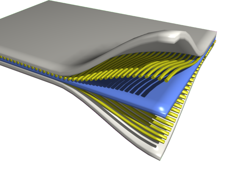
A composite or composite material (also composition material) is a material which is produced from two or more constituent materials.[1] These constituent materials have notably dissimilar chemical or physical properties and are merged to create a material with properties unlike the individual elements. Within the finished structure, the individual elements remain separate and distinct, distinguishing composites from mixtures and solid solutions. Composite materials with more than one distinct layer are called composite laminates.
Typical engineered composite materials are made up of a binding agent forming the matrix and a filler material (particulates or fibres) giving substance, e.g.:
- Concrete, reinforced concrete and masonry with cement, lime or mortar (which is itself a composite material) as a binder
- Composite wood such as glulam and plywood with wood glue as a binder
- Reinforced plastics, such as fiberglass and fibre-reinforced polymer with resin or thermoplastics as a binder
- Ceramic matrix composites (composite ceramic and metal matrices)
- Metal matrix composites[2]
- advanced composite materials, often first developed for spacecraft and aircraft applications.
Composite materials can be less expensive, lighter, stronger or more durable than common materials. Some are inspired by biological structures found in plants and animals.[3] Robotic materials are composites that include sensing, actuation, computation, and communication components.[4][5]
Composite materials are used for construction and technical structures such as boat hulls, swimming pool panels, racing car bodies, shower stalls, bathtubs, storage tanks, imitation granite, and cultured marble sinks and countertops.[6][7] They are also being increasingly used in general automotive applications.[8]
History
[edit]The earliest composite materials were made from straw and mud combined to form bricks for building construction. Ancient brick-making was documented by Egyptian tomb paintings.[9]
Wattle and daub might be the oldest composite materials, at over 6000 years old.[10]
- Woody plants, both true wood from trees and such plants as palms and bamboo, yield natural composites that were used prehistorically by humankind and are still used widely in construction and scaffolding.
- Plywood, 3400 BC,[11] by the Ancient Mesopotamians; gluing wood at different angles gives better properties than natural wood.
- Cartonnage, layers of linen or papyrus soaked in plaster dates to the First Intermediate Period of Egypt c. 2181–2055 BC[11] and was used for death masks.
- Cob mud bricks, or mud walls, (using mud (clay) with straw or gravel as a binder) have been used for thousands of years.[12]
- Concrete was described by Vitruvius, writing around 25 BC in his Ten Books on Architecture, distinguished types of aggregate appropriate for the preparation of lime mortars. For structural mortars, he recommended pozzolana, which were volcanic sands from the sandlike beds of Pozzuoli brownish-yellow-gray in colour near Naples and reddish-brown at Rome. Vitruvius specifies a ratio of 1 part lime to 3 parts pozzolana for cements used in buildings and a 1:2 ratio of lime to pulvis Puteolanus for underwater work, essentially the same ratio mixed today for concrete used at sea.[13] Natural cement-stones, after burning, produced cements used in concretes from post-Roman times into the 20th century, with some properties superior to manufactured Portland cement.
- Papier-mâché, a composite of paper and glue, has been used for hundreds of years.[14]
- The first artificial fibre reinforced plastic was a combination of fiber glass and bakelite, performed in 1935 by Al Simison and Arthur D Little in Owens Corning Company[15]
- One of the most common and familiar composite is fibreglass, in which small glass fibre are embedded within a polymeric material (normally an epoxy or polyester). The glass fibre is relatively strong and stiff (but also brittle), whereas the polymer is ductile (but also weak and flexible). Thus the resulting fibreglass is relatively stiff, strong, flexible, and ductile.[16]
- Composite bow
- Leather cannon, wooden cannon
Examples
[edit]Composite materials
[edit]
Concrete is the most common artificial composite material of all. As of 2009[update], about 7.5 billion cubic metres of concrete are made each year.[17] Concrete typically consists of loose stones (construction aggregate) held with a matrix of cement. Concrete is an inexpensive material resisting large compressive forces,[18] however, susceptible to tensile loading.[19] To give concrete the ability to resist being stretched, steel bars, which can resist high stretching (tensile) forces, are often added to concrete to form reinforced concrete.[20]

Fibre-reinforced polymers include carbon-fiber-reinforced polymers and glass-reinforced plastic. If classified by matrix then there are thermoplastic composites, short fibre thermoplastics, long fibre thermoplastics or long-fiber-reinforced thermoplastics. There are numerous thermoset composites, including paper composite panels. Many advanced thermoset polymer matrix systems usually incorporate aramid fibre and carbon fibre in an epoxy resin matrix.[21][22]
Shape-memory polymer composites are high-performance composites, formulated using fibre or fabric reinforcements and shape-memory polymer resin as the matrix. Since a shape-memory polymer resin is used as the matrix, these composites have the ability to be easily manipulated into various configurations when they are heated above their activation temperatures and will exhibit high strength and stiffness at lower temperatures. They can also be reheated and reshaped repeatedly without losing their material properties. These composites are ideal for applications such as lightweight, rigid, deployable structures; rapid manufacturing; and dynamic reinforcement.[23][24]
High strain composites are another type of high-performance composites that are designed to perform in a high deformation setting and are often used in deployable systems where structural flexing is advantageous.[citation needed] Although high strain composites exhibit many similarities to shape-memory polymers, their performance is generally dependent on the fibre layout as opposed to the resin content of the matrix.[25]
Composites can also use metal fibres reinforcing other metals, as in metal matrix composites (MMC)[26] or ceramic matrix composites (CMC),[27] which includes bone (hydroxyapatite reinforced with collagen fibres), cermet (ceramic and metal), and concrete. Ceramic matrix composites are built primarily for fracture toughness, not for strength. Another class of composite materials involve woven fabric composite consisting of longitudinal and transverse laced yarns. Woven fabric composites are flexible as they are in form of fabric.
Organic matrix/ceramic aggregate composites include asphalt concrete, polymer concrete, mastic asphalt, mastic roller hybrid, dental composite, syntactic foam, and mother of pearl.[28] Chobham armour is a special type of composite armour used in military applications.[citation needed]
Additionally, thermoplastic composite materials can be formulated with specific metal powders resulting in materials with a density range from 2 g/cm3 to 11 g/cm3 (same density as lead). The most common name for this type of material is "high gravity compound" (HGC), although "lead replacement" is also used. These materials can be used in place of traditional materials such as aluminium, stainless steel, brass, bronze, copper, lead, and even tungsten in weighting, balancing (for example, modifying the centre of gravity of a tennis racquet), vibration damping, and radiation shielding applications. High density composites are an economically viable option when certain materials are deemed hazardous and are banned (such as lead) or when secondary operations costs (such as machining, finishing, or coating) are a factor.[29]
There have been several studies indicating that interleaving stiff and brittle epoxy-based carbon-fiber-reinforced polymer laminates with flexible thermoplastic laminates can help to make highly toughened composites that show improved impact resistance.[30] Another interesting aspect of such interleaved composites is that they are able to have shape memory behaviour without needing any shape-memory polymers or shape-memory alloys e.g. balsa plies interleaved with hot glue,[31] aluminium plies interleaved with acrylic polymers or PVC[32] and carbon-fiber-reinforced polymer laminates interleaved with polystyrene.[33]

A sandwich-structured composite is a special class of composite material that is fabricated by attaching two thin but stiff skins to a lightweight but thick core. The core material is normally low strength material, but its higher thickness provides the sandwich composite with high bending stiffness with overall low density.[34][35]

Wood is a naturally occurring composite comprising cellulose fibres in a lignin and hemicellulose matrix.[36] Engineered wood includes a wide variety of different products such as wood fibre board, plywood, oriented strand board, wood plastic composite (recycled wood fibre in polyethylene matrix), Pykrete (sawdust in ice matrix), plastic-impregnated or laminated paper or textiles, Arborite, Formica (plastic), and Micarta. Other engineered laminate composites, such as Mallite, use a central core of end grain balsa wood, bonded to surface skins of light alloy or GRP. These generate low-weight, high rigidity materials.[37]
Particulate composites have particle as filler material dispersed in matrix, which may be nonmetal, such as glass, epoxy. Automobile tire is an example of particulate composite.[38]
Advanced diamond-like carbon (DLC) coated polymer composites have been reported[39] where the coating increases the surface hydrophobicity, hardness and wear resistance.
Ferromagnetic composites, including those with a polymer matrix consisting, for example, of nanocrystalline filler of Fe-based powders and polymers matrix. Amorphous and nanocrystalline powders obtained, for example, from metallic glasses can be used. Their use makes it possible to obtain ferromagnetic nanocomposites with controlled magnetic properties.[40]
Products
[edit]Fibre-reinforced composite materials have gained popularity (despite their generally high cost) in high-performance products that need to be lightweight, yet strong enough to take harsh loading conditions such as aerospace components (tails, wings, fuselages, propellers), boat and scull hulls, bicycle frames, and racing car bodies. Other uses include fishing rods, storage tanks, swimming pool panels, and baseball bats. The Boeing 787 and Airbus A350 structures including the wings and fuselage are composed largely of composites.[41] Composite materials are also becoming more common in the realm of orthopedic surgery,[42] and it is the most common hockey stick material.
Carbon composite is a key material in today's launch vehicles and heat shields for the re-entry phase of spacecraft. It is widely used in solar panel substrates, antenna reflectors and yokes of spacecraft. It is also used in payload adapters, inter-stage structures and heat shields of launch vehicles. Furthermore, disk brake systems of airplanes and racing cars are using carbon/carbon material, and the composite material with carbon fibres and silicon carbide matrix has been introduced in luxury vehicles and sports cars.
In 2006, a fibre-reinforced composite pool panel was introduced for in-ground swimming pools, residential as well as commercial, as a non-corrosive alternative to galvanized steel.
In 2007, an all-composite military Humvee was introduced by TPI Composites Inc and Armor Holdings Inc, the first all-composite military vehicle. By using composites the vehicle is lighter, allowing higher payloads.[43] In 2008, carbon fibre and DuPont Kevlar (five times stronger than steel) were combined with enhanced thermoset resins to make military transit cases by ECS Composites creating 30-percent lighter cases with high strength.
Pipes and fittings for various purpose like transportation of potable water, fire-fighting, irrigation, seawater, desalinated water, chemical and industrial waste, and sewage are now manufactured in glass reinforced plastics.
Composite materials used in tensile structures for facade application provides the advantage of being translucent. The woven base cloth combined with the appropriate coating allows better light transmission. This provides a very comfortable level of illumination compared to the full brightness of outside.[44]
Wind turbine blades, in growing sizes in the order of 50 m length are fabricated in composites since several years.[45] Composites are also used for marine energy structures like tidal turbine blades.[46]
Amputees can run on carbon-fiber composite prosthetic lower legs as fast as non-amputees.[47]
High-pressure gas cylinders typically about 7–9 litre volume x 300 bar pressure for firemen are nowadays constructed from carbon composite. Type-4-cylinders include metal only as boss that carries the thread to screw in the valve.
On 5 September 2019, HMD Global unveiled the Nokia 6.2 and Nokia 7.2 which are claimed to be using polymer composite for the frames.[48]
Overview
[edit]
Composite materials are created from individual materials. These individual materials are known as constituent materials, and there are two main categories of it. One is the matrix (binder) and the other reinforcement.[49] A portion of each kind is needed at least. The reinforcement receives support from the matrix as the matrix surrounds the reinforcement and maintains its relative positions. The properties of the matrix are improved as the reinforcements impart their exceptional physical and mechanical properties. The mechanical properties become unavailable from the individual constituent materials by synergism. At the same time, the designer of the product or structure receives options to choose an optimum combination from the variety of matrix and strengthening materials.
To shape the engineered composites, it must be formed. The reinforcement is placed onto the mould surface or into the mould cavity. Before or after this, the matrix can be introduced to the reinforcement. The matrix undergoes a melding event which sets the part shape necessarily. This melding event can happen in several ways, depending upon the matrix nature, such as solidification from the melted state for a thermoplastic polymer matrix composite or chemical polymerization for a thermoset polymer matrix.
According to the requirements of end-item design, various methods of moulding can be used. The natures of the chosen matrix and reinforcement are the key factors influencing the methodology. The gross quantity of material to be made is another main factor. To support high capital investments for rapid and automated manufacturing technology, vast quantities can be used. Cheaper capital investments but higher labour and tooling expenses at a correspondingly slower rate assists the small production quantities.
Many commercially produced composites use a polymer matrix material often called a resin solution. There are many different polymers available depending upon the starting raw ingredients. There are several broad categories, each with numerous variations. The most common are known as polyester, vinyl ester, epoxy, phenolic, polyimide, polyamide, polypropylene, PEEK, and others. The reinforcement materials are often fibres but also commonly ground minerals. The various methods described below have been developed to reduce the resin content of the final product, or the fibre content is increased. As a rule of thumb, lay up results in a product containing 60% resin and 40% fibre, whereas vacuum infusion gives a final product with 40% resin and 60% fibre content. The strength of the product is greatly dependent on this ratio.
Martin Hubbe and Lucian A Lucia consider wood to be a natural composite of cellulose fibres in a matrix of lignin.[50][51]
Cores in composites
[edit]Several layup designs of composite also involve a co-curing or post-curing of the prepreg with many other media, such as foam or honeycomb. Generally, this is known as a sandwich structure. This is a more general layup for the production of cowlings, doors, radomes or non-structural parts.
Open- and closed-cell-structured foams like polyvinyl chloride, polyurethane, polyethylene, or polystyrene foams, balsa wood, syntactic foams, and honeycombs are generally utilized core materials. Open- and closed-cell metal foam can also be utilized as core materials. Recently, 3D graphene structures ( also called graphene foam) have also been employed as core structures. A recent review by Khurram and Xu et al., have provided the summary of the state-of-the-art techniques for fabrication of the 3D structure of graphene, and the examples of the use of these foam like structures as a core for their respective polymer composites.[52]
Semi-crystalline polymers
[edit]Although the two phases are chemically equivalent, semi-crystalline polymers can be described both quantitatively and qualitatively as composite materials. The crystalline portion has a higher elastic modulus and provides reinforcement for the less stiff, amorphous phase. Polymeric materials can range from 0% to 100%[53] crystallinity aka volume fraction depending on molecular structure and thermal history. Different processing techniques can be employed to vary the percent crystallinity in these materials and thus the mechanical properties of these materials as described in the physical properties section. This effect is seen in a variety of places from industrial plastics like polyethylene shopping bags to spiders which can produce silks with different mechanical properties.[54] In many cases these materials act like particle composites with randomly dispersed crystals known as spherulites. However they can also be engineered to be anisotropic and act more like fiber reinforced composites.[55] In the case of spider silk, the properties of the material can even be dependent on the size of the crystals, independent of the volume fraction.[56] Ironically, single component polymeric materials are some of the most easily tunable composite materials known.
Methods of fabrication
[edit]Normally, the fabrication of composite includes wetting, mixing or saturating the reinforcement with the matrix. The matrix is then induced to bind together (with heat or a chemical reaction) into a rigid structure. Usually, the operation is done in an open or closed forming mould. However, the order and ways of introducing the constituents alters considerably. Composites fabrication is achieved by a wide variety of methods, including advanced fibre placement (automated fibre placement),[57] fibreglass spray lay-up process,[58] filament winding,[59] lanxide process,[60] tailored fibre placement,[61] tufting,[62] and z-pinning.[63]
Overview of mould
[edit]The reinforcing and matrix materials are merged, compacted, and cured (processed) within a mould to undergo a melding event. The part shape is fundamentally set after the melding event. However, under particular process conditions, it can deform. The melding event for a thermoset polymer matrix material is a curing reaction that is caused by the possibility of extra heat or chemical reactivity such as an organic peroxide. The melding event for a thermoplastic polymeric matrix material is a solidification from the melted state. The melding event for a metal matrix material such as titanium foil is a fusing at high pressure and a temperature near the melting point.
It is suitable for many moulding methods to refer to one mould piece as a "lower" mould and another mould piece as an "upper" mould. Lower and upper does not refer to the mould's configuration in space, but the different faces of the moulded panel. There is always a lower mould, and sometimes an upper mould in this convention. Part construction commences by applying materials to the lower mould. Lower mould and upper mould are more generalized descriptors than more common and specific terms such as male side, female side, a-side, b-side, tool side, bowl, hat, mandrel, etc. Continuous manufacturing utilizes a different nomenclature.
Usually, the moulded product is referred to as a panel. It can be referred to as casting for certain geometries and material combinations. It can be referred to as a profile for certain continuous processes. Some of the processes are autoclave moulding,[64] vacuum bag moulding,[65] pressure bag moulding,[66] resin transfer moulding,[67] and light resin transfer moulding.[68]
Other fabrication methods
[edit]Other types of fabrication include casting,[69] centrifugal casting,[70] braiding (onto a former), continuous casting,[71] filament winding,[72] press moulding,[73] transfer moulding, pultrusion moulding,[74] and slip forming.[75] There are also forming capabilities including CNC filament winding, vacuum infusion, wet lay-up, compression moulding, and thermoplastic moulding, to name a few. The practice of curing ovens and paint booths is also required for some projects.
Finishing methods
[edit]The composite parts finishing is also crucial in the final design. Many of these finishes will involve rain-erosion coatings or polyurethane coatings.
Tooling
[edit]The mould and mould inserts are referred to as "tooling". The mould/tooling can be built from different materials. Tooling materials include aluminium, carbon fibre, invar, nickel, reinforced silicone rubber and steel. The tooling material selection is normally based on, but not limited to, the coefficient of thermal expansion, expected number of cycles, end item tolerance, desired or expected surface condition, cure method, glass transition temperature of the material being moulded, moulding method, matrix, cost, and other various considerations.
Physical properties
[edit]
Usually, the composite's physical properties are dependent on the direction of consideration, and so are anisotropic. This applies to many properties including elastic modulus,[76] ultimate tensile strength, thermal conductivity, and electrical conductivity.[77] The rule of mixtures and inverse rule of mixtures give upper and lower bounds for these properties. The real value will lie somewhere between these values and can depend on many factors including:
- the orientation of interest
- the length of the fibres
- the accuracy of the fibre alignment
- the properties of the matrix and fibres
- delamination of the fibres and matrix
- the inclusion of any impurities

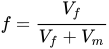
For some material property , the rule of mixtures states that the overall property in the direction parallel to the fibers could be as high as


The inverse rule of mixtures states that in the direction perpendicular to the fibers, the elastic modulus of a composite could be as low as

where
- is the volume fraction of the fibers
- is the material property of the composite parallel to the fibers
- is the material property of the composite perpendicular to the fibers
- is the material property of the fibers
- is the material property of the matrix


The majority of commercial composites are formed with random dispersion and orientation of the strengthening fibres, in which case the composite Young's modulus will fall between the isostrain and isostress bounds. However, in applications where the strength-to-weight ratio is engineered to be as high as possible (such as in the aerospace industry), fibre alignment may be tightly controlled.
In contrast to composites, isotropic materials (for example, aluminium or steel), in standard wrought forms, possess the same stiffness typically despite the directional orientation of the applied forces and/or moments. The relationship between forces/moments and strains/curvatures for an isotropic material can be described with the following material properties: Young's Modulus, the shear modulus, and the Poisson's ratio, in relatively simple mathematical relationships. For the anisotropic material, it needs the mathematics of a second-order tensor and up to 21 material property constants. For the special case of orthogonal isotropy, there are three distinct material property constants for each of Young's Modulus, Shear Modulus and Poisson's ratio—a total of 9 constants to express the relationship between forces/moments and strains/curvatures.
Techniques that take benefit of the materials' anisotropic properties involve mortise and tenon joints (in natural composites such as wood) and pi joints in synthetic composites.
Mechanical properties of composites
[edit]Particle reinforcement
[edit]In general, particle reinforcement is strengthening the composites less than fiber reinforcement. It is used to enhance the stiffness of the composites while increasing the strength and the toughness. Because of their mechanical properties, they are used in applications in which wear resistance is required. For example, hardness of cement can be increased by reinforcing gravel particles, drastically. Particle reinforcement a highly advantageous method of tuning mechanical properties of materials since it is very easy implement while being low cost.[79][80][81][82]
The elastic modulus of particle-reinforced composites can be expressed as,

where E is the elastic modulus, V is the volume fraction. The subscripts c, p and m are indicating composite, particle and matrix, respectively. is a constant can be found empirically.

Similarly, tensile strength of particle-reinforced composites can be expressed as,

where T.S. is the tensile strength, and is a constant (not equal to ) that can be found empirically.

Short fiber reinforcement (shear lag theory)
[edit]Short fibers are often cheaper or more convenient to manufacture than longer continuous fibers, but still provide better properties than particle reinforcement. A common example is carbon fiber reinforced 3D printing filaments, which use chopped short carbon fibers mixed into a matrix, typically PLA or PETG.
Shear lag theory uses the shear lag model to predict properties such as the Young's modulus for short fiber composites. The model assumes that load is transferred from the matrix to the fibers solely through the interfacial shear stresses acting on the cylindrical interface. Shear lag theory says then that the rate of change of the axial stress in the fiber as you move along the fiber is proportional to the ratio of the interfacial shear stresses over the radius of the fibre :


This leads to the average fiber stress over the full length of the fibre being given by:

where
- is the macroscopic strain in the composite
- is the fiber aspect ratio (length over diameter)
- is a dimensionless constant[83]
- is the Poisson's ratio of the matrix


By assuming a uniform tensile strain, this results in:[84]

As s becomes larger, this tends towards the rule of mixtures, which represents the Young's modulus parallel to continuous fibers.
Continuous fiber reinforcement
[edit]In general, continuous fiber reinforcement is implemented by incorporating a fiber as the strong phase into a weak phase, matrix. The reason for the popularity of fiber usage is materials with extraordinary strength can be obtained in their fiber form. Non-metallic fibers are usually showing a very high strength to density ratio compared to metal fibers because of the covalent nature of their bonds. The most famous example of this is carbon fibers that have many applications extending from sports gear to protective equipment to space industries.[85][86]
The stress on the composite can be expressed in terms of the volume fraction of the fiber and the matrix.

where is the stress, V is the volume fraction. The subscripts c, f and m are indicating composite, fiber and matrix, respectively.

Although the stress–strain behavior of fiber composites can only be determined by testing, there is an expected trend, three stages of the stress–strain curve. The first stage is the region of the stress–strain curve where both fiber and the matrix are elastically deformed. This linearly elastic region can be expressed in the following form.[85]

where is the stress, is the strain, E is the elastic modulus, and V is the volume fraction. The subscripts c, f, and m are indicating composite, fiber, and matrix, respectively.

After passing the elastic region for both fiber and the matrix, the second region of the stress–strain curve can be observed. In the second region, the fiber is still elastically deformed while the matrix is plastically deformed since the matrix is the weak phase. The instantaneous modulus can be determined using the slope of the stress–strain curve in the second region. The relationship between stress and strain can be expressed as,

where is the stress, is the strain, E is the elastic modulus, and V is the volume fraction. The subscripts c, f, and m are indicating composite, fiber, and matrix, respectively. To find the modulus in the second region derivative of this equation can be used since the slope of the curve is equal to the modulus.

In most cases it can be assumed since the second term is much less than the first one.[85]

In reality, the derivative of stress with respect to strain is not always returning the modulus because of the binding interaction between the fiber and matrix. The strength of the interaction between these two phases can result in changes in the mechanical properties of the composite. The compatibility of the fiber and matrix is a measure of internal stress.[85]
The covalently bonded high strength fibers (e.g. carbon fibers) experience mostly elastic deformation before the fracture since the plastic deformation can happen due to dislocation motion. Whereas, metallic fibers have more space to plastically deform, so their composites exhibit a third stage where both fiber and the matrix are plastically deforming. Metallic fibers have many applications to work at cryogenic temperatures that is one of the advantages of composites with metal fibers over nonmetallic. The stress in this region of the stress–strain curve can be expressed as,

where is the stress, is the strain, E is the elastic modulus, and V is the volume fraction. The subscripts c, f, and m are indicating composite, fiber, and matrix, respectively. and are for fiber and matrix flow stresses respectively. Just after the third region the composite exhibit necking. The necking strain of composite is happened to be between the necking strain of the fiber and the matrix just like other mechanical properties of the composites. The necking strain of the weak phase is delayed by the strong phase. The amount of the delay depends upon the volume fraction of the strong phase.[85]


Thus, the tensile strength of the composite can be expressed in terms of the volume fraction.[85]

where T.S. is the tensile strength, is the stress, is the strain, E is the elastic modulus, and V is the volume fraction. The subscripts c, f, and m are indicating composite, fiber, and matrix, respectively. The composite tensile strength can be expressed as
- for is less than or equal to (arbitrary critical value of volume fraction)
- for is greater than or equal to



The critical value of volume fraction can be expressed as,
![{\displaystyle V_{c}={\frac {[(T.S.)_{m}-\sigma _{m}(\epsilon _{f})]}{[(T.S.)_{f}+(T.S.)_{m}-\sigma _{m}(\epsilon _{f})]}}}](https://wikimedia.org/api/rest_v1/media/math/render/svg/9a0cb48f61c071d3675fabb7c708af485af0ade4)
Evidently, the composite tensile strength can be higher than the matrix if is greater than .


Thus, the minimum volume fraction of the fiber can be expressed as,
![{\displaystyle V_{c}={\frac {[(T.S.)_{m}-\sigma _{m}(\epsilon _{f})]}{[(T.S.)_{f}-\sigma _{m}(\epsilon _{f})]}}}](https://wikimedia.org/api/rest_v1/media/math/render/svg/8b4d04ff78d317dd93bc5657b9443fbe953067a7)
Although this minimum value is very low in practice, it is very important to know since the reason for the incorporation of continuous fibers is to improve the mechanical properties of the materials/composites, and this value of volume fraction is the threshold of this improvement.[85]
The effect of fiber orientation
[edit]Aligned fibers
[edit]A change in the angle between the applied stress and fiber orientation will affect the mechanical properties of fiber-reinforced composites, especially the tensile strength. This angle, , can be used predict the dominant tensile fracture mechanism.

At small angles, , the dominant fracture mechanism is the same as with load-fiber alignment, tensile fracture. The resolved force acting upon the length of the fibers is reduced by a factor of from rotation. . The resolved area on which the fiber experiences the force is increased by a factor of from rotation. . Taking the effective tensile strength to be and the aligned tensile strength .[85]







At moderate angles, , the material experiences shear failure. The effective force direction is reduced with respect to the aligned direction. . The resolved area on which the force acts is . The resulting tensile strength depends on the shear strength of the matrix, .[85]



At extreme angles, , the dominant mode of failure is tensile fracture in the matrix in the perpendicular direction. As in the isostress case of layered composite materials, the strength in this direction is lower than in the aligned direction. The effective areas and forces act perpendicular to the aligned direction so they both scale by . The resolved tensile strength is proportional to the transverse strength, .[85]



The critical angles from which the dominant fracture mechanism changes can be calculated as,
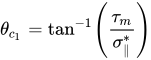
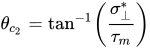
where is the critical angle between longitudinal fracture and shear failure, and is the critical angle between shear failure and transverse fracture.[85]


By ignoring length effects, this model is most accurate for continuous fibers and does not effectively capture the strength-orientation relationship for short fiber reinforced composites. Furthermore, most realistic systems do not experience the local maxima predicted at the critical angles.[87][88][89][90] The Tsai-Hill criterion provides a more complete description of fiber composite tensile strength as a function of orientation angle by coupling the contributing yield stresses: , , and .[91][85]

![{\displaystyle ({\mbox{T.S.}})_{\mbox{c}}\;({\mbox{Tsai-Hill}})={\bigg [}{\frac {\cos ^{4}\theta }{({\sigma _{\parallel }^{*}})^{2}}}+\cos ^{2}\theta \sin ^{2}\theta \left({\frac {1}{({\tau _{m}})^{2}}}-{\frac {1}{({\sigma _{\parallel }^{*}})^{2}}}\right)+{\frac {\sin ^{4}\theta }{({\sigma _{\perp }^{*}})^{2}}}{\bigg ]}^{-1/2}}](https://wikimedia.org/api/rest_v1/media/math/render/svg/970bbbef62730b15a7123400d6ff5504eb672a7b)
Randomly oriented fibers
[edit]Anisotropy in the tensile strength of fiber reinforced composites can be removed by randomly orienting the fiber directions within the material. It sacrifices the ultimate strength in the aligned direction for an overall, isotropically strengthened material.

Where K is an empirically determined reinforcement factor; similar to the particle reinforcement equation. For fibers with randomly distributed orientations in a plane, , and for a random distribution in 3D, .[85]


Stiffness and Compliance Elasticity
[edit]Composite materials are generally anisotropic, and in many cases are orthotropic. Voigt notation can be used to reduce the rank of the stress and strain tensors such that the stiffness (often also referred to by ) and compliance can be written as a matrix:[92]


and
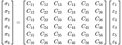
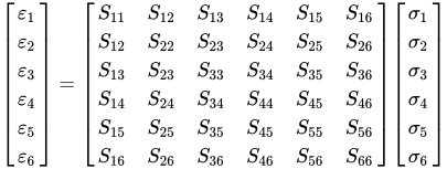
When considering each ply individually, it is assumed that they can be treated as thi lamina and so out–of–plane stresses and strains are negligible. That is and .[93] This allows the stiffness and compliance matrices to be reduced to 3x3 matrices as follows:


and


For fiber-reinforced composite, the fiber orientation in material affect anisotropic properties of the structure. From characterizing technique i.e. tensile testing, the material properties were measured based on sample (1-2) coordinate system. The tensors above express stress-strain relationship in (1-2) coordinate system. While the known material properties is in the principal coordinate system (x-y) of material. Transforming the tensor between two coordinate system help identify the material properties of the tested sample. The transformation matrix with degree rotation is [93]
for for




Types of fibers and mechanical properties
[edit]The most common types of fibers used in industry are glass fibers, carbon fibers, and kevlar due to their ease of production and availability. Their mechanical properties are very important to know, therefore the table of their mechanical properties is given below to compare them with S97 steel.[94][95][96][97] The angle of fiber orientation is very important because of the anisotropy of fiber composites (please see the section "Physical properties" for a more detailed explanation). The mechanical properties of the composites can be tested using standard mechanical testing methods by positioning the samples at various angles (the standard angles are 0°, 45°, and 90°) with respect to the orientation of fibers within the composites. In general, 0° axial alignment makes composites resistant to longitudinal bending and axial tension/compression, 90° hoop alignment is used to obtain resistance to internal/external pressure, and ± 45° is the ideal choice to obtain resistance against pure torsion.[98]
Mechanical properties of fiber composite materials
[edit]| Symbol | Units | Standard
Carbon Fiber Fabric |
High Modulus
Carbon Fiber Fabric |
E-Glass
Fibre Glass Fabric |
Kevlar
Fabric |
Standard
Unidirectional Carbon Fiber Fabric |
High Modulus
Unidirectional Carbon Fiber Fabric |
E-Glass
Unidirectional Fiber Glass Fabric |
Kevlar
Unidirectional Fabric |
Steel
S97 | |
|---|---|---|---|---|---|---|---|---|---|---|---|
| Young's Modulus 0° | E1 | GPa | 70 | 85 | 25 | 30 | 135 | 175 | 40 | 75 | 207 |
| Young's Modulus 90° | E2 | GPa | 70 | 85 | 25 | 30 | 10 | 8 | 8 | 6 | 207 |
| In-plane Shear Modulus | G12 | GPa | 5 | 5 | 4 | 5 | 5 | 5 | 4 | 2 | 80 |
| Major Poisson's Ratio | v12 | 0.10 | 0.10 | 0.20 | 0.20 | 0.30 | 0.30 | 0.25 | 0.34 | – | |
| Ult. Tensile Strength 0° | Xt | MPa | 600 | 350 | 440 | 480 | 1500 | 1000 | 1000 | 1300 | 990 |
| Ult. Comp. Strength 0° | Xc | MPa | 570 | 150 | 425 | 190 | 1200 | 850 | 600 | 280 | – |
| Ult. Tensile Strength 90° | Yt | MPa | 600 | 350 | 440 | 480 | 50 | 40 | 30 | 30 | – |
| Ult. Comp. Strength 90° | Yc | MPa | 570 | 150 | 425 | 190 | 250 | 200 | 110 | 140 | – |
| Ult. In-plane Shear Stren. | S | MPa | 90 | 35 | 40 | 50 | 70 | 60 | 40 | 60 | – |
| Ult. Tensile Strain 0° | ext | % | 0.85 | 0.40 | 1.75 | 1.60 | 1.05 | 0.55 | 2.50 | 1.70 | – |
| Ult. Comp. Strain 0° | exc | % | 0.80 | 0.15 | 1.70 | 0.60 | 0.85 | 0.45 | 1.50 | 0.35 | – |
| Ult. Tensile Strain 90° | eyt | % | 0.85 | 0.40 | 1.75 | 1.60 | 0.50 | 0.50 | 0.35 | 0.50 | – |
| Ult. Comp. Strain 90° | eyc | % | 0.80 | 0.15 | 1.70 | 0.60 | 2.50 | 2.50 | 1.35 | 2.30 | – |
| Ult. In-plane shear strain | es | % | 1.80 | 0.70 | 1.00 | 1.00 | 1.40 | 1.20 | 1.00 | 3.00 | – |
| Density | g/cc | 1.60 | 1.60 | 1.90 | 1.40 | 1.60 | 1.60 | 1.90 | 1.40 | – |
| Symbol | Units | Standard
Carbon Fiber |
High Modulus
Carbon Fiber |
E-Glass
Fiber Glass |
Standard
Carbon Fibers Fabric |
E-Glass
Fiber Glass Fabric |
Steel | Al | |
|---|---|---|---|---|---|---|---|---|---|
| Longitudinal Modulus | E1 | GPa | 17 | 17 | 12.3 | 19.1 | 12.2 | 207 | 72 |
| Transverse Modulus | E2 | GPa | 17 | 17 | 12.3 | 19.1 | 12.2 | 207 | 72 |
| In Plane Shear Modulus | G12 | GPa | 33 | 47 | 11 | 30 | 8 | 80 | 25 |
| Poisson's Ratio | v12 | .77 | .83 | .53 | .74 | .53 | |||
| Tensile Strength | Xt | MPa | 110 | 110 | 90 | 120 | 120 | 990 | 460 |
| Compressive Strength | Xc | MPa | 110 | 110 | 90 | 120 | 120 | 990 | 460 |
| In Plane Shear Strength | S | MPa | 260 | 210 | 100 | 310 | 150 | ||
| Thermal Expansion Co-ef | Alpha1 | Strain/K | 2.15 E-6 | 0.9 E-6 | 12 E-6 | 4.9 E-6 | 10 E-6 | 11 E-6 | 23 E-6 |
| Moisture Co-ef | Beta1 | Strain/K | 3.22 E-4 | 2.49 E-4 | 6.9 E-4 |
Carbon fiber & fiberglass composites vs. aluminum alloy and steel
[edit]Although strength and stiffness of steel and aluminum alloys are comparable to fiber composites, specific strength and stiffness of composites (i.e. in relation to their weight) are significantly higher.
| Carbon Fiber Composite (aerospace grade) | Carbon Fiber Composite (commercial grade) | Fiberglass Composite | Aluminum 6061 T-6 | Steel,
Mild | |
| Cost $/LB | $20 – $250+ | $5 – $20 | $1.50 – $3.00 | $3 | $0.30 |
| Strength (psi) | 90,000 – 200,000 | 50,000 – 90,000 | 20,000 – 35,000 | 35,000 | 60,000 |
| Stiffness (psi) | 10 x 106– 50 x 106 | 8 x 10⁶ – 10 x 106 | 1 x 10⁶ – 1.5 x 10⁶ | 10 x 106 | 30 x 106 |
| Density (lb/in3) | 0.050 | 0.050 | 0.055 | 0.10 | 0.30 |
| Specific Strength | 1.8 x 10⁶ – 4 x 10⁶ | 1 x 10⁶ – 1.8 x 10⁶ | 363,640–636,360 | 350,000 | 200,000 |
| Specific Stiffness | 200 x 106 – 1,000 x 106 | 160 x 106 – 200 x 106 | 18 x 106 – 27 x 106 | 100 x 106 | 100 x 106 |
Failure
[edit]Shock, impact of varying speed, or repeated cyclic stresses can provoke the laminate to separate at the interface between two layers, a condition known as delamination.[101][102] Individual fibres can separate from the matrix, for example, fibre pull-out.
Composites can fail on the macroscopic or microscopic scale. Compression failures can happen at both the macro scale or at each individual reinforcing fibre in compression buckling. Tension failures can be net section failures of the part or degradation of the composite at a microscopic scale where one or more of the layers in the composite fail in tension of the matrix or failure of the bond between the matrix and fibres.
Some composites are brittle and possess little reserve strength beyond the initial onset of failure while others may have large deformations and have reserve energy absorbing capacity past the onset of damage. The distinctions in fibres and matrices that are available and the mixtures that can be made with blends leave a very broad range of properties that can be designed into a composite structure. The most famous failure of a brittle ceramic matrix composite occurred when the carbon-carbon composite tile on the leading edge of the wing of the Space Shuttle Columbia fractured when impacted during take-off. It directed to the catastrophic break-up of the vehicle when it re-entered the Earth's atmosphere on 1 February 2003.
Composites have relatively poor bearing strength compared to metals.

Another failure mode is fiber tensile fracture, which becomes more likely when fibers are aligned with the loading direction, so is the possibility of fiber tensile fracture, assuming the tensile strength exceeds that of the matrix. When a fiber has some angle of misorientation θ, several fracture modes are possible. For small values of θ the stress required to initiate fracture is increased by a factor of (cos θ)−2 due to the increased cross-sectional area (A cos θ) of the fibre and reduced force (F/cos θ) experienced by the fiber, leading to a composite tensile strength of σparallel /cos2 θ where σparallel is the tensile strength of the composite with fibers aligned parallel with the applied force.
Intermediate angles of misorientation θ lead to matrix shear failure. Again the cross sectional area is modified but since shear stress is now the driving force for failure the area of the matrix parallel to the fibers is of interest, increasing by a factor of 1/sin θ. Similarly, the force parallel to this area again decreases (F/cos θ) leading to a total tensile strength of τmy /sin θ cos θ where τmy is the matrix shear strength.
Finally, for large values of θ (near π/2) transverse matrix failure is the most likely to occur, since the fibers no longer carry the majority of the load. Still, the tensile strength will be greater than for the purely perpendicular orientation, since the force perpendicular to the fibers will decrease by a factor of 1/sin θ and the area decreases by a factor of 1/sin θ producing a composite tensile strength of σperp /sin2θ where σperp is the tensile strength of the composite with fibers align perpendicular to the applied force.[103]
Testing
[edit]Composites are tested before and after construction to assist in predicting and preventing failures. Pre-construction testing may adopt finite element analysis (FEA) for ply-by-ply analysis of curved surfaces and predicting wrinkling, crimping and dimpling of composites.[104][105][106][107] Materials may be tested during manufacturing and after construction by various non-destructive methods including ultrasonic, thermography, shearography and X-ray radiography,[108] and laser bond inspection for NDT of relative bond strength integrity in a localized area.
See also
[edit]- 3D composites
- Aluminium composite panel
- American Composites Manufacturers Association
- Chemical vapour infiltration
- Composite laminate
- Discontinuous aligned composite
- Epoxy granite
- Hybrid material
- Lay-up process
- Nanocomposite
- Pykrete
- Rule of mixtures
- Scaled Composites
- Smart material
- Smart Materials and Structures
- Void (composites)
References
[edit]- ^ "What are Composites". Discover Composites. Archived from the original on 2021-05-22. Retrieved 2020-12-18.
- ^ Zhou, M.Y.; Ren, L.B.; Fan, L.L.; Zhang, Y.W.X.; Lu, T.H.; Quan, G.F.; Gupta, M. (October 2020). "Progress in research on hybrid metal matrix composites". Journal of Alloys and Compounds. 838 155274. doi:10.1016/j.jallcom.2020.155274.
- ^ Nepal, Dhriti; Kang, Saewon; Adstedt, Katarina M.; Kanhaiya, Krishan; Bockstaller, Michael R.; Brinson, L. Catherine; Buehler, Markus J.; Coveney, Peter V.; Dayal, Kaushik; El-Awady, Jaafar A.; Henderson, Luke C.; Kaplan, David L.; Keten, Sinan; Kotov, Nicholas A.; Schatz, George C.; Vignolini, Silvia; Vollrath, Fritz; Wang, Yusu; Yakobson, Boris I.; Tsukruk, Vladimir V.; Heinz, Hendrik (January 2023). "Hierarchically structured bioinspired nanocomposites". Nature Materials. 22 (1): 18–35. Bibcode:2023NatMa..22...18N. doi:10.1038/s41563-022-01384-1. hdl:1721.1/148578. PMID 36446962.
- ^ McEvoy, M. A.; Correll, N. (19 March 2015). "Materials that couple sensing, actuation, computation, and communication". Science. 347 (6228) 1261689. Bibcode:2015Sci...34761689M. doi:10.1126/science.1261689. PMID 25792332.
- ^ "Autonomous Materials Will Let Future Robots Change Color And Shift Shape". popsci.com. 20 March 2015. Archived from the original on 27 September 2017. Retrieved 3 May 2018.
- ^ "Composites | Composite Materials". Mar-Bal, Inc. 2013-10-15. Archived from the original on 2015-11-13. Retrieved 2020-12-18.
- ^ "Applications | Composites UK". compositesuk.co.uk. Archived from the original on 2015-02-26. Retrieved 2020-12-18.
- ^ "Achieving Class A Appearance On Fiber-Reinforced Substrates". www.coatingstech-digital.org. Archived from the original on 2021-09-20. Retrieved 2021-06-24.
- ^ Haka, Andreas. Engineered Stability.The History of Composite Materials. Cham: Springer 2023 Chap. 1 on "Early composites".
- ^ Shaffer, Gary D. (Spring 1993). "An Archaeomagnetic Study of a Wattle and Daub Building Collapse". Journal of Field Archaeology. 20 (1): 59–75. doi:10.2307/530354. JSTOR 530354.
- ^ a b "History of Composite Materials". Mar-Bal Incorporated. 2013-08-19. Archived from the original on 2018-01-04. Retrieved 2018-01-03.
- ^ "Is Cob A Composite?". expandusceramics.com. 27 August 2019. Archived from the original on 2021-05-23. Retrieved 2020-12-19.
- ^ Lechtmann, Heather; Hobbs, Linn (1986). "Roman Concrete and the Roman Architectural Revolution". In Kingery, W. D.; Lense, Esther (eds.). High-technology Ceramics: Past, Present, and Future: The Nature of Innovation and Change in Ceramic Technology. American Caeramic Society. pp. 81–128. ISBN 978-0-608-00723-6.
- ^ "Papier Mache - Articles - Papier Mache And Paper Clay". www.papiermache.co.uk. Archived from the original on 2011-04-29. Retrieved 2020-12-19.
- ^ Owens corning milestones 2017[verification needed]
- ^ "What is Fibreglass or Fiberglass?". www.fibreglassdirect.co.uk. Archived from the original on 2020-09-30. Retrieved 2020-12-19.
- ^ "Minerals commodity summary – cement – 2009". US United States Geological Survey. 1 June 2007. Archived from the original on 13 December 2007. Retrieved 16 January 2008.
- ^ "Slabs On Grade". Construction Knowldegs.net. Archived from the original on October 2, 2017. Retrieved January 3, 2018.
- ^ "Behaviour of Concrete Under Tension". The Constructor. 2012-12-06. Archived from the original on January 4, 2018. Retrieved January 3, 2018.
- ^ "Reinforced concrete". www.designingbuildings.co.uk. Archived from the original on 2016-07-11. Retrieved 2020-12-17.
- ^ Reeve, Scott. "3 Reasons to use Fiber-Reinforced Polymer (FRP)". www.compositeadvantage.com. Archived from the original on 2020-10-24. Retrieved 2020-12-17.
- ^ "A Beginner's Guide to Fiber Reinforced Plastics (FRP's) - Craftech Industries - High-Performance Plastics - (518) 828-5001". Craftech Industries. 2014-08-05. Archived from the original on 2017-05-14. Retrieved 2020-12-17.
- ^ "Shape Memory Polymers - A Complete Guide". www.bpf.co.uk. Archived from the original on 2021-05-23. Retrieved 2020-12-17.
- ^ "Shape Memory Polymers | Sheffield Hallam University". www.shu.ac.uk. Archived from the original on 2021-05-23. Retrieved 2020-12-17.
- ^ "Tensile Fiber Failure on High Strain Composites" (PDF). University of Colorado, Boulder. Archived (PDF) from the original on May 23, 2021. Retrieved Dec 17, 2020.
- ^ "7: Metal Matrix Composites | School of Materials Science and Engineering". www.materials.unsw.edu.au. Archived from the original on 2021-01-25. Retrieved 2020-12-17.
- ^ "What are Ceramic Matrix Composites?". L&L Special Furnace. 30 August 2018.
- ^ "Composite Material". hi-techindia. Archived from the original on 2021-03-03. Retrieved 2020-12-21.
- ^ "Thermoplastic Composites - An Introduction". AZoM.com. 2001-02-15. Archived from the original on 2012-04-05. Retrieved 2020-12-17.
- ^ Quan, Dong; Bologna, Francesca; Scarselli, Gennaro; Ivankovic, Alojz; Murphy, Neal (January 2020). "Interlaminar fracture toughness of aerospace-grade carbon fibre reinforced plastics interleaved with thermoplastic veils". Composites Part A: Applied Science and Manufacturing. 128 105642. doi:10.1016/j.compositesa.2019.105642.
- ^ Gordon, Benjamin; Clark, William (2007). "Morphing Structures by way of Stiffness Variations". 48th AIAA/ASME/ASCE/AHS/ASC Structures, Structural Dynamics, and Materials Conference. doi:10.2514/6.2007-1717. ISBN 978-1-62410-013-0.
- ^ Gandhi, Farhan; Kang, Sang-Guk (1 August 2007). "Beams with controllable flexural stiffness". Smart Materials and Structures. 16 (4): 1179–1184. Bibcode:2007SMaS...16.1179G. doi:10.1088/0964-1726/16/4/028. hdl:10203/25282.
- ^ Robinson, Paul; Bismarck, Alexander; Zhang, Bohao; Maples, Henry A. (June 2017). "Deployable, shape memory carbon fibre composites without shape memory constituents". Composites Science and Technology. 145: 96–104. doi:10.1016/j.compscitech.2017.02.024. hdl:10044/1/49550.
- ^ "What is a sandwich structure?". www.twi-global.com. Archived from the original on 2021-05-23. Retrieved 2020-12-17.
- ^ "Basics of sandwich technology". www.diabgroup.com. Archived from the original on 2018-02-26. Retrieved 2020-12-17.
- ^ "Is Wood A Composite Material or A Pure Substance?". WoodWoodLand. 2019-07-09. Archived from the original on 2020-08-12. Retrieved 2020-12-17.
- ^ "Composite wood; what is it? Origin and advantages". Silvadec. Archived from the original on 2017-12-01. Retrieved 2020-12-17.
- ^ Staab, George H. (1999). "Introduction to Composite Materials". Laminar Composites. pp. 1–16. doi:10.1016/B978-075067124-8/50001-1. ISBN 978-0-7506-7124-8.
A particulate composite is characterized as being composed of particles suspended in a matrix. Particles can have virtually any shape, size or configuration. Examples of well-known particulate composites are concrete and particle board. There are two subclasses of particulates: flake and filled/skeletal
- ^ Zia, Abdul Wasy; Shah, Atta Ur Rehman; Lee, Seunghun; Song, Jung Il (2015). "Development of diamond-like-carbon coated abaca-reinforced polyester composites for hydrophobic and outdoor structural applications". Polymer Bulletin. 72 (11): 2797–2808. doi:10.1007/s00289-015-1436-y.
- ^ Nowosielski, Ryszard; Gramatyka, Paweł; Sakiewicz, Piotr; Babilas, Rafał (August 2015). "Ferromagnetic composites with polymer matrix consisted of nanocrystalline Fe-based filler". Journal of Magnetism and Magnetic Materials. 387: 179–185. Bibcode:2015JMMM..387..179N. doi:10.1016/j.jmmm.2015.04.004.
- ^ "Airbus takes on Boeing with composite A350 XWB". Materials Today. Archived from the original on 2015-10-23. Retrieved 2020-12-17.
- ^ Longo, Joseph A.; Koeneman, James B. (2000). "Orthopedic Applications of Carbon Fiber Composites". Biomaterials Engineering and Devices: Human Applications. pp. 203–214. doi:10.1007/978-1-59259-197-8_12. ISBN 978-1-61737-227-8.
- ^ "TPI Composites and Armor Holdings Unveil Army's First All-Composite Military Vehicle". www.businesswire.com. 2007-07-20. Archived from the original on 2021-05-23. Retrieved 2020-12-21.
- ^ "The pros and cons of fabric structures | Span Design". Archived from the original on 2009-07-27. Retrieved 2018-09-24.
- ^ "Wind Power Blades Energize Composites Manufacturing". www.ptonline.com. October 2008. Archived from the original on 2011-02-16. Retrieved 2020-12-21.
- ^ Lusty, Ariel F; Murdy, Paul; Gionet-Gonzales, Julia A (2024). "Submerged Fatigue Testing of Marine Energy Advanced Materials". doi:10.13140/RG.2.2.34441.25445.
{{cite journal}}: Cite journal requires|journal=(help) - ^ Nolan, Lee (2008-01-01). "Carbon fibre prostheses and running in amputees: A review". Foot and Ankle Surgery. Special Issue. 14 (3): 125–129. doi:10.1016/j.fas.2008.05.007. ISSN 1268-7731.
- ^ "HMD Global debuts two killer mid-range Nokia phones". Android Authority. 2019-09-05. Archived from the original on 2019-09-13. Retrieved 2020-12-17.
- ^ "Composite materials - Using materials - AQA - GCSE Chemistry (Single Science) Revision - AQA". BBC Bitesize. Archived from the original on 2021-05-23. Retrieved 2020-12-18.
- ^ Hubbe, Martin A.; Lucia, Lucian A. (2007). "The 'love-hate' relationship present in lignocellulosic materials". BioResources. 2 (4): 534–535. doi:10.15376/BIORES.2.4.534-535.
- ^ Hon, David N.S.; Shiraishi, Nobuo (2000). Wood and Cellulosic Chemistry, Revised, and Expanded. p. 5 ff. doi:10.1201/9781482269741. ISBN 978-0-429-17533-6. OCLC 50869397.
- ^ Shehzad, Khurram; Xu, Yang; Gao, Chao; Duan, Xiangfeng (2016). "Three-dimensional macro-structures of two-dimensional nanomaterials". Chemical Society Reviews. 45 (20): 5541–5588. doi:10.1039/c6cs00218h. PMID 27459895.
- ^ Agbolaghi, Samira; Abbaspoor, Saleheh; Abbasi, Farhang (June 2018). "A comprehensive review on polymer single crystals—From fundamental concepts to applications". Progress in Polymer Science. 81: 22–79. doi:10.1016/j.progpolymsci.2017.11.006.
- ^ Termonia, Yves (December 1994). "Molecular Modeling of Spider Silk Elasticity". Macromolecules. 27 (25): 7378–7381. Bibcode:1994MaMol..27.7378T. doi:10.1021/ma00103a018.
- ^ Quan, Hui; Li, Zhong-Ming; Yang, Ming-Bo; Huang, Rui (June 2005). "On transcrystallinity in semi-crystalline polymer composites". Composites Science and Technology. 65 (7–8): 999–1021. doi:10.1016/j.compscitech.2004.11.015.
- ^ Keten, Sinan; Xu, Zhiping; Ihle, Britni; Buehler, Markus J. (14 March 2010). "Nanoconfinement controls stiffness, strength and mechanical toughness of β-sheet crystals in silk". Nature Materials. 9 (4): 359–367. Bibcode:2010NatMa...9..359K. doi:10.1038/nmat2704. PMID 20228820.
- ^ drawpub. "Automated Fiber Placement". Automated Dynamics - Composite Structures, Automation Equipment, and Engineering Services. Archived from the original on 2014-04-12. Retrieved 2020-12-17.
- ^ "Lay-up methods for fibreglass composites | Resin Library". Archived from the original on 2023-01-22. Retrieved 2020-12-17.
- ^ "Filament Winding - Open Molding". CompositesLab. Archived from the original on 2015-09-27. Retrieved 2020-12-17.
- ^ Yamaguchi, Y. (1994-08-01). "Unique methods of making MMC and CMC by Lanxide process; Lanxide hoshiki ni yoru CMC oyobi MMC no seiho". Seramikkusu (Ceramics Japan) (in Japanese). 29. Archived from the original on 2021-05-23. Retrieved 2020-12-17.
- ^ Pye, Andy (2020-03-12). "Tailored Fibre Placement - complex composite designs delivered at speed with reduced waste". Prospector Knowledge Center. Archived from the original on 2021-05-23. Retrieved 2020-12-17.
- ^ Dell'Anno, G.; Treiber, J.W.G.; Partridge, I.K. (February 2016). "Manufacturing of composite parts reinforced through-thickness by tufting". Robotics and Computer-Integrated Manufacturing. 37: 262–272. doi:10.1016/j.rcim.2015.04.004. hdl:1983/a2f04bfb-1b46-4029-9318-aa47f9c29f2f.
- ^ "Z pinning - CSIR - NAL". www.nal.res.in. Archived from the original on 2020-11-10. Retrieved 2020-12-17.
- ^ "Autoclave molding - CSIR - NAL". www.nal.res.in. Archived from the original on 2020-08-05. Retrieved 2020-12-18.
- ^ "Vacuum bag moulding - CSIR - NAL". www.nal.res.in. Archived from the original on 2020-08-06. Retrieved 2020-12-18.
- ^ "Pressure Bag Moulding". NetComposites. Archived from the original on 2020-11-10. Retrieved 2020-12-18.
- ^ "Resin Transfer Moulding Processes - CSIR - NAL". www.nal.res.in. Archived from the original on 2020-08-06. Retrieved 2020-12-18.
- ^ "Light Resin Transfer Molding: CompositesWorld". www.compositesworld.com. Archived from the original on 2014-07-22. Retrieved 2020-12-18.
- ^ "Composite Casting Processes". www.sicomin.com. Archived from the original on 2020-05-14. Retrieved 2020-12-20.
- ^ "Centrifugal Casting - Closed Molding". CompositesLab. Archived from the original on 2015-09-26. Retrieved 2020-12-20.
- ^ Kwaśniewski, Paweł; Kiesiewicz, Grzegorz (2014). "Studies on Obtaining Cu-CNT Composites by Continuous Casting Method". Metallurgy and Foundry Engineering. 40 (2): 83. doi:10.7494/mafe.2014.40.2.83.
- ^ "Filament Winding". NetComposites. Archived from the original on 2021-05-23. Retrieved 2020-12-20.
- ^ "PRESS MOULDING OF AUTOMOTIVE COMPOSITES – Shape Group". Archived from the original on 2020-09-20. Retrieved 2020-12-20.
- ^ Shrivastava, Anshuman (2018). "Plastics Processing". Introduction to Plastics Engineering. pp. 143–177. doi:10.1016/B978-0-323-39500-7.00005-8. ISBN 978-0-323-39500-7.
The term 'pultrusion' combines the word 'pull' and 'extrusion.' It is a continuous manufacturing process to produce products with constant cross sections such as profiles and sheets. Fig. 5.25 is a schematic illustration of general pultrusion setup. As shown in the figure, continuous fiber reinforcements are saturated (wet out) with desired resin matrix either in a resin bath or in resin injection chamber. The coated fibers then pass through heating and forming dies where curing of the resin and forming of the shape occur. After the die the composite is allowed to postcure while being pulled to the saw which cuts it into stock length. Different resin–fiber combinations are used to achieve the final desired properties
- ^ [1], "System and method for slip forming monolithic reinforced composite concrete structures having multiple functionally discrete components", issued 2015-05-24 Archived 2021-06-08 at the Wayback Machine
- ^ Alger, Mark. S. M. (1997). Polymer Science Dictionary (2nd ed.). Springer Publishing. ISBN 0-412-60870-7.
- ^ Askeland, Donald R.; Fulay, Pradeep P.; Wright, Wendelin J. (2010-06-21). The Science and Engineering of Materials (6th ed.). Cengage Learning. ISBN 978-0-495-29602-7.
- ^ Kim, Hyoung Seop (September 2000). "On the rule of mixtures for the hardness of particle reinforced composites". Materials Science and Engineering: A. 289 (1–2): 30–33. doi:10.1016/S0921-5093(00)00909-6.
- ^ Wu, Xiangguo; Yang, Jing; Mpalla, Issa B. (25 December 2013). "Preliminary design and structural responses of typical hybrid wind tower made of ultra high performance cementitious composites". Structural Engineering and Mechanics. 48 (6): 791–807. doi:10.12989/sem.2013.48.6.791.
- ^ Li, Mo; Li, Victor C. (March 2013). "Rheology, fiber dispersion, and robust properties of Engineered Cementitious Composites". Materials and Structures. 46 (3): 405–420. doi:10.1617/s11527-012-9909-z. hdl:2027.42/94214.
- ^ "Large-Scale Processing of Engineered Cementitious Composites". ACI Materials Journal. 105 (4). 2008. doi:10.14359/19897.
- ^ Zeidi, Mahdi; Kim, Chun IL; Park, Chul B. (2021). "The role of interface on the toughening and failure mechanisms of thermoplastic nanocomposites reinforced with nanofibrillated rubbers". Nanoscale. 13 (47): 20248–20280. doi:10.1039/D1NR07363J. PMID 34851346.
- ^ John A. Nairn (1997). "On the Use of Shear-Lag Methods for Analysis of Stress Transfer in Unidirectional Composites". Mechanics of Materials. 26 (2): 63–80. Bibcode:1997MechM..26...63N. doi:10.1016/S0167-6636(97)00023-9.
- ^ P.J. WITHERS (2000). "4.02 - Elastic and Thermoelastic Properties of Brittle Matrix Composites". Comprehensive Composite Materials: 25–45. doi:10.1016/B0-08-042993-9/00087-5. ISBN 978-0-08-042993-9.
- ^ a b c d e f g h i j k l m Courtney, Thomas H. (2005). Mechanical Behavior of Materials. Waveland Press. ISBN 978-1-4786-0838-7.[page needed]
- ^ Park, Soo-Jin (2018). Carbon Fibers. Springer Series in Materials Science. Vol. 210. doi:10.1007/978-981-13-0538-2. ISBN 978-981-13-0537-5.[page needed]
- ^ Lasikun; Ariawan, Dody; Surojo, Eko; Triyono, Joko (2018). "Effect of fiber orientation on tensile and impact properties of Zalacca Midrib fiber-HDPE composites by compression molding". The 3rd International Conference on Industrial. AIP Conference Proceedings. 1927 (1). Jatinangor, Indonesia: 030060. Bibcode:2018AIPC.1931c0060L. doi:10.1063/1.5024119.
- ^ Mortazavian, Seyyedvahid; Fatemi, Ali (April 2015). "Effects of fiber orientation and anisotropy on tensile strength and elastic modulus of short fiber reinforced polymer composites". Composites Part B: Engineering. 72: 116–129. doi:10.1016/j.compositesb.2014.11.041.
- ^ Banakar, Prashanth; Shivananda, H K; Niranjan, H B (March 2012). "Influence of Fiber Orientation and Thickness on Tensile Properties of Laminated Polymer Composites". International Journal of Pure and Applied Sciences and Technology. 9 (1): 61–68. ProQuest 1030964421.
- ^ Brahim, Sami Ben; Cheikh, Ridha Ben (January 2007). "Influence of fibre orientation and volume fraction on the tensile properties of unidirectional Alfa-polyester composite". Composites Science and Technology. 67 (1): 140–147. doi:10.1016/j.compscitech.2005.10.006.
- ^ Azzi, V. D.; Tsai, S.W. (1965). "Anisotropic Strength of Composites". Experimental Mechanics. 5 (9): 283–288. doi:10.1007/BF02326292.
- ^ Lekhnit͡skiĭ, Sergeĭ Georgievich (1963). Theory of Elasticity of an Anisotropic Elastic Body. Holden-Day. OCLC 652279972.[page needed]
- ^ a b Soares, Carlos A. Mota; Soares, Cristóvão M. Mota; Freitas, Manuel J. M., eds. (1999). Mechanics of Composite Materials and Structures. doi:10.1007/978-94-011-4489-6. ISBN 978-0-7923-5871-8.
- ^ "Carbon Fibre, Tubes, Profiles – Filament Winding and Composite Engineering". www.performance-composites.com. Archived from the original on 2020-05-05. Retrieved 2020-05-22.
- ^ "Composite Manufacturing | Performance Composites". www.performancecomposites.com. Archived from the original on 2020-05-03. Retrieved 2020-05-22.
- ^ "Composite Materials • Innovative Composite Engineering". Innovative Composite Engineering. Archived from the original on 2020-05-05. Retrieved 2020-05-22.
- ^ "Reinforcement Fabrics – In Stock for Same Day Shipping | Fibre Glast". www.fibreglast.com. Archived from the original on 2020-07-16. Retrieved 2020-05-22.
- ^ "Filament Winding, Carbon Fibre Angles in Composite Tubes". www.performance-composites.com. Archived from the original on 2020-05-05. Retrieved 2020-05-22.
- ^ a b "Mechanical Properties of Carbon Fibre Composite Materials". www.performance-composites.com. Archived from the original on 2020-06-03. Retrieved 2020-05-22.
- ^ "Carbon Fiber Composite Design Guide" (PDF). www.performancecomposites.com. Archived (PDF) from the original on 2020-10-30. Retrieved 2020-05-22.
- ^ Ma, Binlin; Cao, Xiaofei; Feng, Yu; Song, Yujian; Yang, Fei; Li, Ying; Zhang, Deyue; Wang, Yipeng; He, Yuting (February 2024). "A comparative study on the low velocity impact behavior of UD, woven, and hybrid UD/woven FRP composite laminates". Composites Part B: Engineering. 271 111133. doi:10.1016/j.compositesb.2023.111133.
- ^ Sanchez-Saez, S.; Barbero, E.; Zaera, R.; Navarro, C. (October 2005). "Compression after impact of thin composite laminates". Composites Science and Technology. 65 (13): 1911–1919. doi:10.1016/j.compscitech.2005.04.009. hdl:10016/7498.
- ^ Courtney, Thomas H. (2000). Mechanical Behavior of Materials (2nd ed.). Long Grove, IL: Waveland Press, Inc. pp. 263–265. ISBN 978-1-57766-425-3.
- ^ Waterman, Pamela (1 May 2007). "The Life of Composite Materials". Digital Engineering.
- ^ Aghdam, M.M.; Morsali, S.R. (November 2013). "Damage initiation and collapse behavior of unidirectional metal matrix composites at elevated temperatures". Computational Materials Science. 79: 402–407. doi:10.1016/j.commatsci.2013.06.024.
- ^ Debnath, Kishore; Singh, Inderdeep, eds. (2017). Primary and Secondary Manufacturing of Polymer Matrix Composites. doi:10.1201/9781351228466. ISBN 978-1-351-22846-6.[page needed]
- ^ What is Finite Element Analysis?[permanent dead link]
- ^ Matzkanin, George A.; Yolken, H. Thomas. "Techniques for the Nondestructive Evaluation of Polymer Matrix Composites" (PDF). AMMTIAC Quarterly. 2 (4). Archived from the original (PDF) on 2008-12-17.
Further reading
[edit]- Jones, Robert M. (2018). Mechanics of Composite Materials. doi:10.1201/9781498711067. ISBN 978-1-315-27298-6.
- Aboudi, Jacob; Cederbaum, Gabriel; Elishakoff, Isaac; Librescu, Liviu (1992). Random Vibration and Reliability of Composite Structures. CRC Press. ISBN 978-0-87762-865-1.
- Librescu, Liviu; Song, Ohseop (2006). Thin-Walled Composite Beams. Solid Mechanics and Its Applications. Vol. 131. doi:10.1007/1-4020-4203-5. ISBN 978-1-4020-3457-2.
- Palsule, Sanjay, ed. (2016). Polymers and Polymeric Composites: A Reference Series. doi:10.1007/978-3-642-37179-0. ISBN 978-3-642-37179-0.
- Kaw, Autar K. (2005). Mechanics of Composite Materials. doi:10.1201/9781420058291. ISBN 978-0-429-12539-3.
- Hollaway, L. C. (1994). Handbook of Polymer Composites for Engineers. Woodhead Publishing. ISBN 978-1-85573-129-5.
- Madbouly, Samy; Zhang, Chaoqun; Kessler, Michael R. (2015). Bio-Based Plant Oil Polymers and Composites. William Andrew. ISBN 978-0-323-37128-5.
- Matthews, F. L.; Rawlings, Rees D. (1999). Composite Materials: Engineering and Science. Woodhead Publishing. ISBN 978-0-8493-0621-1.
- Haka, Andreas T. (2023). Engineered Stability. doi:10.1007/978-3-658-41408-5. ISBN 978-3-658-41407-8.
External links
[edit]
- cdmHUB – the Global Composites Community
- Distance learning course in polymers and composites
- OptiDAT composite material database Archived 2013-11-04 at the Wayback Machine
| International | |
|---|---|
| National | |
| Other | |
