Hubbry Logo
search
logo
2320919

Microscopy

logo
Community Hub0 Subscribers
Read side by side
from Wikipedia
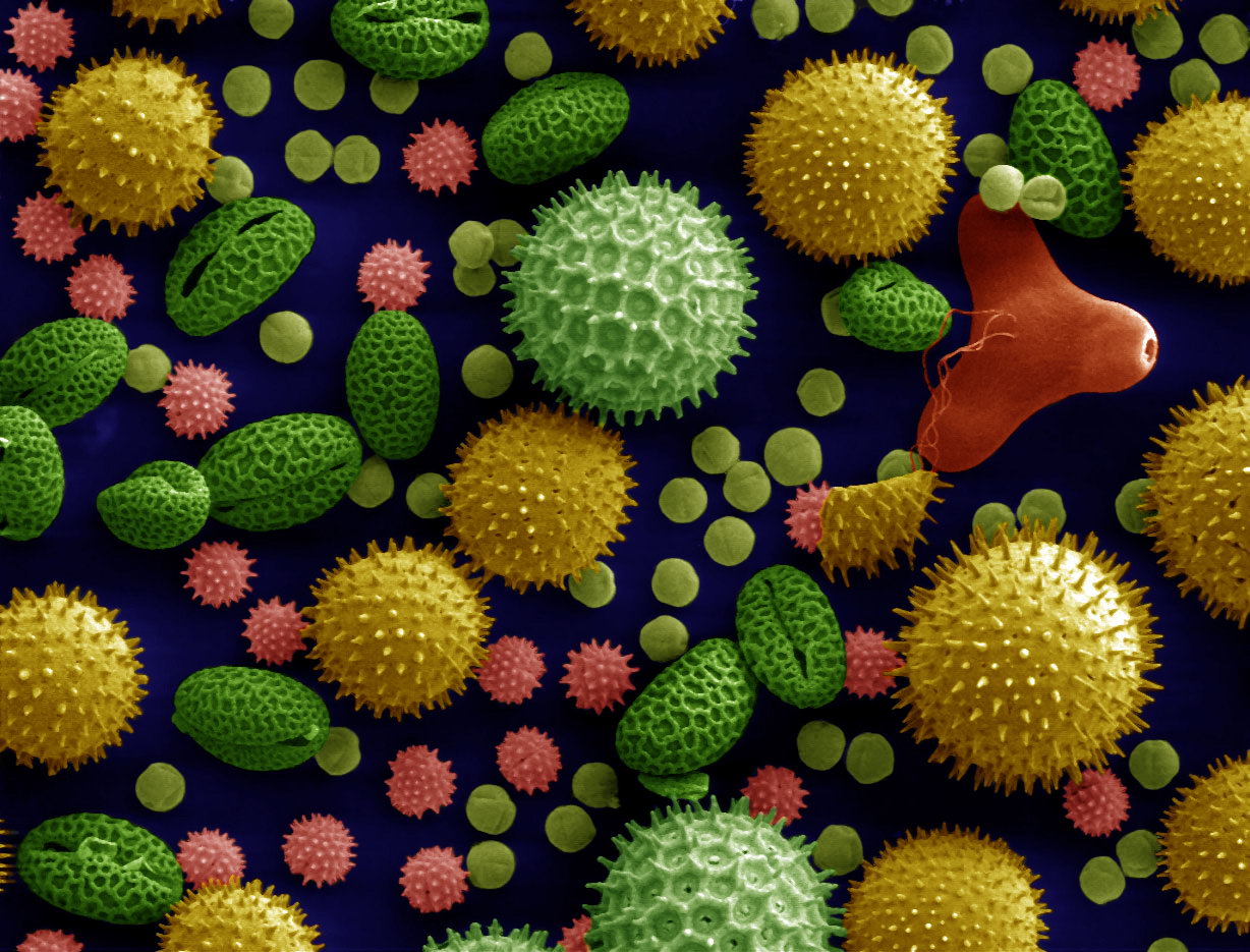
Scanning electron microscope image of pollen (false colors)
Microscopic examination in a biochemical laboratory

Microscopy is the technical field of using microscopes to view subjects too small to be seen with the naked eye (objects that are not within the resolution range of the normal eye).[1] There are three well-known branches of microscopy: optical, electron, and scanning probe microscopy, along with the emerging field of X-ray microscopy.[citation needed]

Optical microscopy and electron microscopy involve the diffraction, reflection, or refraction of electromagnetic radiation/electron beams interacting with the specimen, and the collection of the scattered radiation or another signal in order to create an image. This process may be carried out by wide-field irradiation of the sample (for example standard light microscopy and transmission electron microscopy) or by scanning a fine beam over the sample (for example confocal laser scanning microscopy and scanning electron microscopy). Scanning probe microscopy involves the interaction of a scanning probe with the surface of the object of interest. The development of microscopy revolutionized biology, gave rise to the field of histology and so remains an essential technique in the life and physical sciences. X-ray microscopy is three-dimensional and non-destructive, allowing for repeated imaging of the same sample for in situ or 4D studies, and providing the ability to "see inside" the sample being studied before sacrificing it to higher resolution techniques. A 3D X-ray microscope uses the technique of computed tomography (microCT), rotating the sample 360 degrees and reconstructing the images. CT is typically carried out with a flat panel display. A 3D X-ray microscope employs a range of objectives, e.g., from 4X to 40X, and can also include a flat panel.

History

[edit]
Antonie van Leeuwenhoek (1632–1723)

The field of microscopy (optical microscopy) dates back to at least the 17th-century. Earlier microscopes, single lens magnifying glasses with limited magnification, date at least as far back as the wide spread use of lenses in eyeglasses in the 13th century[2] but more advanced compound microscopes first appeared in Europe around 1620[3][4] The earliest practitioners of microscopy include Galileo Galilei, who found in 1610 that he could close focus his telescope to view small objects close up[5][6] and Cornelis Drebbel, who may have invented the compound microscope around 1620.[7][8] Antonie van Leeuwenhoek developed a very high magnification simple microscope in the 1670s and is often considered to be the first acknowledged microscopist and microbiologist.[9][10]

Optical microscopy

[edit]
Stereo microscope

Optical or light microscopy involves passing visible light transmitted through or reflected from the sample through a single lens or multiple lenses to allow a magnified view of the sample.[11] The resulting image can be detected directly by the eye, imaged on a photographic plate, or captured digitally. The single lens with its attachments, or the system of lenses and imaging equipment, along with the appropriate lighting equipment, sample stage, and support, makes up the basic light microscope. The most recent development is the digital microscope, which uses a CCD camera to focus on the exhibit of interest. The image is shown on a computer screen, so eye-pieces are unnecessary.[12]

Limitations

[edit]

Limitations of standard optical microscopy (bright field microscopy) lie in three areas;

  • The technique can only image dark or strongly refracting objects effectively.
  • There is a diffraction-limited resolution depending on incident wavelength; in visible range, the resolution of optical microscopy is limited to approximately 0.2  micrometres (see: microscope) and the practical magnification limit to ~1500x.[13]
  • Out-of-focus light from points outside the focal plane reduces image clarity.[14]

Live cells in particular generally lack sufficient contrast to be studied successfully, since the internal structures of the cell are colorless and transparent. The most common way to increase contrast is to stain the structures with selective dyes, but this often involves killing and fixing the sample.[15] Staining may also introduce artifacts, which are apparent structural details that are caused by the processing of the specimen and are thus not features of the specimen. In general, these techniques make use of differences in the refractive index of cell structures. Bright-field microscopy is comparable to looking through a glass window: one sees not the glass but merely the dirt on the glass. There is a difference, as glass is a denser material, and this creates a difference in phase of the light passing through. The human eye is not sensitive to this difference in phase, but clever optical solutions have been devised to change this difference in phase into a difference in amplitude (light intensity).[citation needed]

Techniques

[edit]

To improve specimen contrast or highlight structures in a sample, special techniques must be used. A huge selection of microscopy techniques are available to increase contrast or label a sample.

Bright field

[edit]

Bright field microscopy is the simplest of all the light microscopy techniques. Sample illumination is via transmitted white light, i.e. illuminated from below and observed from above. Limitations include low contrast of most biological samples and low apparent resolution due to the blur of out-of-focus material. The simplicity of the technique and the minimal sample preparation required are significant advantages.[citation needed]

Oblique illumination

[edit]

The use of oblique (from the side) illumination gives the image a three-dimensional appearance and can highlight otherwise invisible features. A more recent technique based on this method is Hoffmann's modulation contrast, a system found on inverted microscopes for use in cell culture. Oblique illumination enhances contrast even in clear specimens; however, because light enters off-axis, the position of an object will appear to shift as the focus is changed. This limitation makes techniques like optical sectioning or accurate measurement on the z-axis impossible.

Dark field

[edit]

Dark field microscopy is a technique for improving the contrast of unstained, transparent specimens.[16] Dark field illumination uses a carefully aligned light source to minimize the quantity of directly transmitted (unscattered) light entering the image plane, collecting only the light scattered by the sample. Dark field can dramatically improve image contrast – especially of transparent objects – while requiring little equipment setup or sample preparation. However, the technique suffers from low light intensity in the final image of many biological samples and continues to be affected by low apparent resolution.

A diatom under Rheinberg illumination

Rheinberg illumination is a variant of dark field illumination in which transparent, colored filters are inserted just before the condenser so that light rays at high aperture are differently colored than those at low aperture (i.e., the background to the specimen may be blue while the object appears self-luminous red). Other color combinations are possible, but their effectiveness is quite variable.[17]

Dispersion staining

[edit]

Dispersion staining is an optical technique that results in a colored image of a colorless object. This is an optical staining technique and requires no stains or dyes to produce a color effect. There are five different microscope configurations used in the broader technique of dispersion staining. They include brightfield Becke line, oblique, darkfield, phase contrast, and objective stop dispersion staining.

Phase contrast

[edit]
Phase-contrast light micrograph of undecalcified hyaline cartilage showing chondrocytes and organelles, lacunae and extracellular matrix
In electron microscopy: Phase-contrast imaging

More sophisticated techniques will show proportional differences in optical density. Phase contrast is a widely used technique that shows differences in refractive index as difference in contrast. It was developed by the Dutch physicist Frits Zernike in the 1930s (for which he was awarded the Nobel Prize in 1953). The nucleus in a cell for example will show up darkly against the surrounding cytoplasm. Contrast is excellent; however it is not for use with thick objects. Frequently, a halo is formed even around small objects, which obscures detail. The system consists of a circular annulus in the condenser, which produces a cone of light. This cone is superimposed on a similar sized ring within the phase-objective. Every objective has a different size ring, so for every objective another condenser setting has to be chosen. The ring in the objective has special optical properties: it, first of all, reduces the direct light in intensity, but more importantly, it creates an artificial phase difference of about a quarter wavelength. As the physical properties of this direct light have changed, interference with the diffracted light occurs, resulting in the phase contrast image. One disadvantage of phase-contrast microscopy is halo formation (halo-light ring).

Differential interference contrast

[edit]

Superior and much more expensive is the use of interference contrast. Differences in optical density will show up as differences in relief. A nucleus within a cell will actually show up as a globule in the most often used differential interference contrast system according to Georges Nomarski. However, it has to be kept in mind that this is an optical effect, and the relief does not necessarily resemble the true shape. Contrast is very good and the condenser aperture can be used fully open, thereby reducing the depth of field and maximizing resolution.

The system consists of a special prism (Nomarski prism, Wollaston prism) in the condenser that splits light in an ordinary and an extraordinary beam. The spatial difference between the two beams is minimal (less than the maximum resolution of the objective). After passage through the specimen, the beams are reunited by a similar prism in the objective.

In a homogeneous specimen, there is no difference between the two beams, and no contrast is being generated. However, near a refractive boundary (say a nucleus within the cytoplasm), the difference between the ordinary and the extraordinary beam will generate a relief in the image. Differential interference contrast requires a polarized light source to function; two polarizing filters have to be fitted in the light path, one below the condenser (the polarizer), and the other above the objective (the analyzer).

Note: In cases where the optical design of a microscope produces an appreciable lateral separation of the two beams we have the case of classical interference microscopy, which does not result in relief images, but can nevertheless be used for the quantitative determination of mass-thicknesses of microscopic objects.

Interference reflection

[edit]

An additional technique using interference is interference reflection microscopy (also known as reflected interference contrast, or RIC). It relies on cell adhesion to the slide to produce an interference signal. If there is no cell attached to the glass, there will be no interference.

Interference reflection microscopy can be obtained by using the same elements used by DIC, but without the prisms. Also, the light that is being detected is reflected and not transmitted as it is when DIC is employed.

Fluorescence

[edit]
Images may also contain artifacts. This is a confocal laser scanning fluorescence micrograph of thale cress anther (part of stamen). The picture shows among other things a nice red flowing collar-like structure just below the anther. However, an intact thale cress stamen does not have such collar, this is a fixation artifact: the stamen has been cut below the picture frame, and epidermis (upper layer of cells) of stamen stalk has peeled off, forming a non-characteristic structure. Photo: Heiti Paves from Tallinn University of Technology.

When certain compounds are illuminated with high energy light, they emit light of a lower frequency. This effect is known as fluorescence. Often specimens show their characteristic autofluorescence image, based on their chemical makeup.

This method is of critical importance in the modern life sciences, as it can be extremely sensitive, allowing the detection of single molecules. Many fluorescent dyes can be used to stain structures or chemical compounds. One powerful method is the combination of antibodies coupled to a fluorophore as in immunostaining. Examples of commonly used fluorophores are fluorescein or rhodamine.

The antibodies can be tailor-made for a chemical compound. For example, one strategy often in use is the artificial production of proteins, based on the genetic code (DNA). These proteins can then be used to immunize rabbits, forming antibodies which bind to the protein. The antibodies are then coupled chemically to a fluorophore and used to trace the proteins in the cells under study.

Highly efficient fluorescent proteins such as the green fluorescent protein (GFP) have been developed using the molecular biology technique of gene fusion, a process that links the expression of the fluorescent compound to that of the target protein. This combined fluorescent protein is, in general, non-toxic to the organism and rarely interferes with the function of the protein under study. Genetically modified cells or organisms directly express the fluorescently tagged proteins, which enables the study of the function of the original protein in vivo.

Growth of protein crystals results in both protein and salt crystals. Both are colorless and microscopic. Recovery of the protein crystals requires imaging which can be done by the intrinsic fluorescence of the protein or by using transmission microscopy. Both methods require an ultraviolet microscope as proteins absorbs light at 280 nm. Protein will also fluorescence at approximately 353 nm when excited with 280 nm light.[18]

Since fluorescence emission differs in wavelength (color) from the excitation light, an ideal fluorescent image shows only the structure of interest that was labeled with the fluorescent dye. This high specificity led to the widespread use of fluorescence light microscopy in biomedical research. Different fluorescent dyes can be used to stain different biological structures, which can then be detected simultaneously, while still being specific due to the individual color of the dye.

To block the excitation light from reaching the observer or the detector, filter sets of high quality are needed. These typically consist of an excitation filter selecting the range of excitation wavelengths, a dichroic mirror, and an emission filter blocking the excitation light. Most fluorescence microscopes are operated in the Epi-illumination mode (illumination and detection from one side of the sample) to further decrease the amount of excitation light entering the detector.

See also: total internal reflection fluorescence microscope Neuroscience

Confocal

[edit]

Confocal laser scanning microscopy uses a focused laser beam (e.g. 488 nm) that is scanned across the sample to excite fluorescence in a point-by-point fashion. The emitted light is directed through a pinhole to prevent out-of-focus light from reaching the detector, typically a photomultiplier tube. The image is constructed in a computer, plotting the measured fluorescence intensities according to the position of the excitation laser. Compared to full sample illumination, confocal microscopy gives slightly higher lateral resolution and significantly improves optical sectioning (axial resolution). Confocal microscopy is, therefore, commonly used where 3D structure is important.

A subclass of confocal microscopes are spinning disc microscopes which are able to scan multiple points simultaneously across the sample. A corresponding disc with pinholes rejects out-of-focus light. The light detector in a spinning disc microscope is a digital camera, typically EM-CCD or sCMOS.

Two-photon microscopy

[edit]

A two-photon microscope is also a laser-scanning microscope, but instead of UV, blue or green laser light, a pulsed infrared laser is used for excitation. Only in the tiny focus of the laser is the intensity high enough to generate fluorescence by two-photon excitation, which means that no out-of-focus fluorescence is generated, and no pinhole is necessary to clean up the image.[19] This allows imaging deep in scattering tissue, where a confocal microscope would not be able to collect photons efficiently.[20] Two-photon microscopes with wide-field detection are frequently used for functional imaging, e.g. calcium imaging, in brain tissue.[21] They are marketed as Multiphoton microscopes by several companies, although the gains of using 3-photon instead of 2-photon excitation are marginal.

Single plane illumination microscopy and light sheet fluorescence microscopy

[edit]

Using a plane of light formed by focusing light through a cylindrical lens at a narrow angle or by scanning a line of light in a plane perpendicular to the axis of objective, high resolution optical sections can be taken.[22][23][24] Single plane illumination, or light sheet illumination, is also accomplished using beam shaping techniques incorporating multiple-prism beam expanders.[25][26] The images are captured by CCDs. These variants allow very fast and high signal to noise ratio image capture.

Wide-field multiphoton microscopy

[edit]

Wide-field multiphoton microscopy[27][28][29][30] refers to an optical non-linear imaging technique in which a large area of the object is illuminated and imaged without the need for scanning. High intensities are required to induce non-linear optical processes such as two-photon fluorescence or second harmonic generation. In scanning multiphoton microscopes the high intensities are achieved by tightly focusing the light, and the image is obtained by beam scanning. In wide-field multiphoton microscopy the high intensities are best achieved using an optically amplified pulsed laser source to attain a large field of view (~100 μm).[27][28][29] The image in this case is obtained as a single frame with a CCD camera without the need of scanning, making the technique particularly useful to visualize dynamic processes simultaneously across the object of interest. With wide-field multiphoton microscopy the frame rate can be increased up to a 1000-fold compared to multiphoton scanning microscopy.[28] In scattering tissue, however, image quality rapidly degrades with increasing depth.

Deconvolution

[edit]

Fluorescence microscopy is a powerful technique to show specifically labeled structures within a complex environment and to provide three-dimensional information of biological structures. However, this information is blurred by the fact that, upon illumination, all fluorescently labeled structures emit light, irrespective of whether they are in focus or not. So an image of a certain structure is always blurred by the contribution of light from structures that are out of focus. This phenomenon results in a loss of contrast especially when using objectives with a high resolving power, typically oil immersion objectives with a high numerical aperture.

Mathematically modeled Point Spread Function of a pulsed THz laser imaging system.[31]

However, blurring is not caused by random processes, such as light scattering, but can be well defined by the optical properties of the image formation in the microscope imaging system. If one considers a small fluorescent light source (essentially a bright spot), light coming from this spot spreads out further from our perspective as the spot becomes more out of focus. Under ideal conditions, this produces an "hourglass" shape of this point source in the third (axial) dimension. This shape is called the point spread function (PSF) of the microscope imaging system. Since any fluorescence image is made up of a large number of such small fluorescent light sources, the image is said to be "convolved by the point spread function". The mathematically modeled PSF of a terahertz laser pulsed imaging system is shown on the right.

The output of an imaging system can be described using the equation:

Where n is the additive noise.[32] Knowing this point spread function[33] means that it is possible to reverse this process to a certain extent by computer-based methods commonly known as deconvolution microscopy.[34] There are various algorithms available for 2D or 3D deconvolution. They can be roughly classified in nonrestorative and restorative methods. While the nonrestorative methods can improve contrast by removing out-of-focus light from focal planes, only the restorative methods can actually reassign light to its proper place of origin. Processing fluorescent images in this manner can be an advantage over directly acquiring images without out-of-focus light, such as images from confocal microscopy, because light signals otherwise eliminated become useful information. For 3D deconvolution, one typically provides a series of images taken from different focal planes (called a Z-stack) plus the knowledge of the PSF, which can be derived either experimentally or theoretically from knowing all contributing parameters of the microscope.

Sub-diffraction techniques

[edit]
Example of super-resolution microscopy. Image of Her3 and Her2, target of the breast cancer drug Trastuzumab, within a cancer cell.

A multitude of super-resolution microscopy techniques have been developed in recent times which circumvent the diffraction limit.

This is mostly achieved by imaging a sufficiently static sample multiple times and either modifying the excitation light or observing stochastic changes in the image. The deconvolution methods described in the previous section, which removes the PSF induced blur and assigns a mathematically 'correct' origin of light, are used, albeit with slightly different understanding of what the value of a pixel mean. Assuming most of the time, one single fluorophore contributes to one single blob on one single taken image, the blobs in the images can be replaced with their calculated position, vastly improving resolution to well below the diffraction limit.

To realize such assumption, Knowledge of and chemical control over fluorophore photophysics is at the core of these techniques, by which resolutions of ~20 nanometers are obtained.[35][36]

Serial time-encoded amplified microscopy

[edit]

Serial time encoded amplified microscopy (STEAM) is an imaging method that provides ultrafast shutter speed and frame rate, by using optical image amplification to circumvent the fundamental trade-off between sensitivity and speed, and a single-pixel photodetector to eliminate the need for a detector array and readout time limitations[37] The method is at least 1000 times faster than the state-of-the-art CCD and CMOS cameras. Consequently, it is potentially useful for scientific, industrial, and biomedical applications that require high image acquisition rates, including real-time diagnosis and evaluation of shockwaves, microfluidics, MEMS, and laser surgery.[38]

Extensions

[edit]

Most modern instruments provide simple solutions for micro-photography and image recording electronically. However such capabilities are not always present and the more experienced microscopist may prefer a hand drawn image to a photograph. This is because a microscopist with knowledge of the subject can accurately convert a three-dimensional image into a precise two-dimensional drawing. In a photograph or other image capture system however, only one thin plane is ever in good focus.[citation needed]

The creation of accurate micrographs requires a microscopical technique using a monocular eyepiece. It is essential that both eyes are open and that the eye that is not observing down the microscope is instead concentrated on a sheet of paper on the bench besides the microscope. With practice, and without moving the head or eyes, it is possible to accurately trace the observed shapes by simultaneously "seeing" the pencil point in the microscopical image.[citation needed]

Other enhancements

[edit]

Microspectroscopy:spectroscopy with a microscope

X-ray

[edit]

As resolution depends on the wavelength of the light. Electron microscopy has been developed since the 1930s that use electron beams instead of light. Because of the much smaller wavelength of the electron beam, resolution is far higher.

Though less common, X-ray microscopy has also been developed since the late 1940s. The resolution of X-ray microscopy lies between that of light microscopy and electron microscopy.

Electron microscopy

[edit]

Until the invention of sub-diffraction microscopy, the wavelength of the light limited the resolution of traditional microscopy to around 0.2 micrometers. In order to gain higher resolution, the use of an electron beam with a far smaller wavelength is used in electron microscopes.

  • Transmission electron microscopy (TEM) is quite similar to the compound light microscope, by sending an electron beam through a very thin slice of the specimen. The resolution limit in 2005 was around 0.05 [dubiousdiscuss] nanometer and has not increased appreciably since that time.
  • Scanning electron microscopy (SEM) visualizes details on the surfaces of specimens and gives a very nice 3D view. It gives results much like those of the stereo light microscope. The best resolution for SEM in 2011 was 0.4 nanometer.

Electron microscopes equipped for X-ray spectroscopy can provide qualitative and quantitative elemental analysis. This type of electron microscope, also known as analytical electron microscope, can be a very powerful tool for investigation of nanomaterials.[39]

Scanning probe microscopy

[edit]

This is a sub-diffraction technique. Examples of scanning probe microscopes are the atomic force microscope (AFM), the scanning tunneling microscope, the photonic force microscope and the recurrence tracking microscope. All such methods use the physical contact of a solid probe tip to scan the surface of an object, which is supposed to be almost flat.

Ultrasonic force

[edit]

Ultrasonic force microscopy (UFM) has been developed in order to improve the details and image contrast on "flat" areas of interest where AFM images are limited in contrast. The combination of AFM-UFM allows a near field acoustic microscopic image to be generated. The AFM tip is used to detect the ultrasonic waves and overcomes the limitation of wavelength that occurs in acoustic microscopy. By using the elastic changes under the AFM tip, an image of much greater detail than the AFM topography can be generated.

Ultrasonic force microscopy allows the local mapping of elasticity in atomic force microscopy by the application of ultrasonic vibration to the cantilever or sample. To analyze the results of ultrasonic force microscopy in a quantitative fashion, a force-distance curve measurement is done with ultrasonic vibration applied to the cantilever base, and the results are compared with a model of the cantilever dynamics and tip-sample interaction based on the finite-difference technique.

Ultraviolet microscopy

[edit]

Ultraviolet microscopes have two main purposes. The first is to use the shorter wavelength of ultraviolet electromagnetic energy to improve the image resolution beyond that of the diffraction limit of standard optical microscopes. This technique is used for non-destructive inspection of devices with very small features such as those found in modern semiconductors. The second application for UV microscopes is contrast enhancement where the response of individual samples is enhanced, relative to their surrounding, due to the interaction of light with the molecules within the sample itself. One example is in the growth of protein crystals. Protein crystals are formed in salt solutions. As salt and protein crystals are both formed in the growth process, and both are commonly transparent to the human eye, they cannot be differentiated with a standard optical microscope. As the tryptophan of protein absorbs light at 280 nm, imaging with a UV microscope with 280 nm bandpass filters makes it simple to differentiate between the two types of crystals. The protein crystals appear dark while the salt crystals are transparent.

Infrared microscopy

[edit]

The term infrared microscopy refers to microscopy performed at infrared wavelengths. In the typical instrument configuration, a Fourier Transform Infrared Spectrometer (FTIR) is combined with an optical microscope and an infrared detector. The infrared detector can be a single point detector, a linear array or a 2D focal plane array. FTIR provides the ability to perform chemical analysis via infrared spectroscopy and the microscope and point or array detector enable this chemical analysis to be spatially resolved, i.e. performed at different regions of the sample. As such, the technique is also called infrared microspectroscopy[40][41] An alternative architecture called Laser Direct Infrared (LDIR) Imaging involves the combination of a tuneable infrared light source and single point detector on a flying objective. This technique is frequently used for infrared chemical imaging, where the image contrast is determined by the response of individual sample regions to particular IR wavelengths selected by the user, usually specific IR absorption bands and associated molecular resonances. A key limitation of conventional infrared microspectroscopy is that the spatial resolution is diffraction-limited. Specifically the spatial resolution is limited to a figure related to the wavelength of the light. For practical IR microscopes, the spatial resolution is limited to 1–3x the wavelength, depending on the specific technique and instrument used. For mid-IR wavelengths, this sets a practical spatial resolution limit of ~3-30 μm.

IR versions of sub-diffraction microscopy also exist.[40][41] These include IR Near-field scanning optical microscope (NSOM),[42] photothermal microspectroscopy and atomic force microscope based infrared spectroscopy (AFM-IR), as well as scattering-type Scanning Near-field Optical Microscopy (s-SNOM)[43] & nano-FTIR that provide nanoscale spatial resolution at IR wavelengths.

Digital holographic microscopy

[edit]
Human cells imaged by DHM phase shift (left) and phase contrast microscopy (right)

In digital holographic microscopy (DHM), interfering wave fronts from a coherent (monochromatic) light-source are recorded on a sensor. The image is digitally reconstructed by a computer from the recorded hologram. Besides the ordinary bright field image, a phase shift image is created.

DHM can operate both in reflection and transmission mode. In reflection mode, the phase shift image provides a relative distance measurement and thus represents a topography map of the reflecting surface. In transmission mode, the phase shift image provides a label-free quantitative measurement of the optical thickness of the specimen. Phase shift images of biological cells are very similar to images of stained cells and have successfully been analyzed by high content analysis software.

A unique feature of DHM is the ability to adjust focus after the image is recorded, since all focus planes are recorded simultaneously by the hologram. This feature makes it possible to image moving particles in a volume or to rapidly scan a surface. Another attractive feature is The ability of DHM to use low cost optics by correcting optical aberrations by software.

Digital pathology (virtual microscopy)

[edit]

Digital pathology is an image-based information environment enabled by computer technology that allows for the management of information generated from a digital slide. Digital pathology is enabled in part by virtual microscopy, which is the practice of converting glass slides into digital slides that can be viewed, managed, and analyzed.

Laser microscopy

[edit]

Laser microscopy is a rapidly growing field that uses laser illumination sources in various forms of microscopy.[44] For instance, laser microscopy focused on biological applications uses ultrashort pulse lasers, in a number of techniques labeled as nonlinear microscopy, saturation microscopy, and two-photon excitation microscopy.[45]

High-intensity, short-pulse laboratory x-ray lasers have been under development for several years. When this technology comes to fruition, it will be possible to obtain magnified three-dimensional images of elementary biological structures in the living state at a precisely defined instant. For optimum contrast between water and protein and for best sensitivity and resolution, the laser should be tuned near the nitrogen line at about 0.3 nanometers. Resolution will be limited mainly by the hydrodynamic expansion that occurs while the necessary number of photons is being registered.[46] Thus, while the specimen is destroyed by the exposure, its configuration can be captured before it explodes.[47][48][49][50][51][52][excessive citations]

Scientists have been working on practical designs and prototypes for x-ray holographic microscopes, despite the prolonged development of the appropriate laser.[53][54][55][56][57][58][59][60][excessive citations]

Photoacoustic microscopy

[edit]
Photoacoustic micrograph of human red blood cells.

A microscopy technique relying on the photoacoustic effect,[61] i.e. the generation of (ultra)sound caused by light absorption. A focused and intensity modulated laser beam is raster scanned over a sample. The generated (ultra)sound is detected via an ultrasound transducer. Commonly piezoelectric ultrasound transducers are employed.[62]

The image contrast is related to the sample's absorption coefficient . This is in contrast to bright or dark field microscopy, where the image contrast is due to transmittance or scattering. In principle, the contrast of fluorescence microscopy is proportional to the sample's absorption too. However, in fluorescence microscopy the fluorescence quantum yield needs to be unequal to zero in order that a signal can be detected. In photoacoustic microscopy, however, every absorbing substance gives a photoacoustic signal which is proportional to

Here is the Grüneisen coefficient, is the laser's photon energy and is the sample's band gap energy. Therefore, photoacoustic microscopy seems well suited as a complementary technique to fluorescence microscopy, as a high fluorescence quantum yield leads to high fluorescence signals and a low fluorescence quantum yield leads to high photoacoustic signals.

Neglecting non-linear effects, the lateral resolution dx is limited by the Abbe diffraction limit:

where is the wavelength of the excitation laser and NA is the numerical aperture of the objective lens. The Abbe diffraction limit holds if the incoming wave front is parallel. In reality, however, the laser beam profile is Gaussian. Therefore, in order to the calculate the achievable resolution, formulas for truncated Gaussian beams have to be used.[63]

Amateur microscopy

[edit]

Amateur Microscopy is the investigation and observation of biological and non-biological specimens for recreational purposes. Collectors of minerals, insects, seashells, and plants may use microscopes as tools to uncover features that help them classify their collected items. Other amateurs may be interested in observing the life found in pond water and of other samples. Microscopes may also prove useful for the water quality assessment for people that keep a home aquarium. Photographic documentation and drawing of the microscopic images are additional pleasures. There are competitions for photomicrograph art. Participants of this pastime may use commercially prepared microscopic slides or prepare their own slides.

While microscopy is a central tool in the documentation of biological specimens, it is often insufficient to justify the description of a new species based on microscopic investigations alone. Often genetic and biochemical tests are necessary to confirm the discovery of a new species. A laboratory and access to academic literature is a necessity. There is, however, one advantage that amateurs have above professionals: time to explore their surroundings. Often, advanced amateurs team up with professionals to validate their findings and possibly describe new species.

In the late 1800s, amateur microscopy became a popular hobby in the United States and Europe. Several 'professional amateurs' were being paid for their sampling trips and microscopic explorations by philanthropists, to keep them amused on the Sunday afternoon (e.g., the diatom specialist A. Grunow, being paid by (among others) a Belgian industrialist). Professor John Phin published "Practical Hints on the Selection and Use of the Microscope (Second Edition, 1878)," and was also the editor of the "American Journal of Microscopy."

Examples of amateur microscopy images:

Application in forensic science

[edit]

Microscopy has applications in the forensic sciences.[64] The microscope can detect, resolve and image the smallest items of evidence, often without any alteration or destruction. The microscope is used to identify and compare fibers, hairs, soils, and dust...etc.

In ink markings, blood stains or bullets, no specimen treatment is required and the evidence shows directly from microscopical examination. For traces of particular matter, the sample preparation must be done before microscopical examination occurs.[clarification needed]

Light microscopes are the most use in forensics, using photons to form images, microscopes which are most applicable for examining forensic specimens are as follows:[65]

1. The compound microscope

2. The comparison microscope

3. The stereoscopic microscope

4. The polarizing microscope

5. The micro spectrophotometer

This diversity of the types of microscopes in forensic applications comes mainly from their magnification ranges, which are (1- 1200X), (50 -30,000X) and (500- 250,000X) for the optical microscopy, SEM and TEM respectively.[65]

See also

[edit]

References

[edit]

Further reading

[edit]
[edit]
Revisions and contributorsEdit on WikipediaRead on Wikipedia
from Grokipedia
Microscopy is the science and technical field of using microscopes to visualize and study objects and specimens that are too small to be seen with the unaided human eye, typically extending observation capabilities to scales ranging from micrometers (10⁻⁶ meters) to nanometers (10⁻⁹ meters).[1][2] These instruments achieve this by magnifying images through lenses or electron beams, revealing intricate details in biological cells, microorganisms, materials, and subatomic structures that have profoundly advanced fields like biology, medicine, and materials science.[1][2] The origins of microscopy trace back to the 17th century, when early compound microscopes were developed in Europe, with significant contributions from scientists such as Robert Hooke, who published Micrographia in 1665 describing observations of cork cells and other microstructures, and Antony van Leeuwenhoek, known as the "father of microbiology" for his single-lens microscopes that achieved up to 270× magnification and enabled the first sightings of bacteria, protozoa, and blood cells in the 1670s and 1680s.[3][2] Over the subsequent centuries, microscope design evolved dramatically: the 18th and 19th centuries saw improvements in lens quality, including achromatic objectives invented by Chester Moor Hall in 1733 to reduce chromatic aberration, and Ernst Abbe's formulation of the resolution limit in 1873—defined as approximately λ / (2 n sin α), where λ is the wavelength of light, n is the refractive index, and α is the half-angle of the light cone—which set the theoretical boundary for optical resolution at about 0.2 micrometers using visible light.[3] Key 19th- and 20th-century advancements included apochromatic lenses by Otto Schott and Carl Zeiss in 1886 for superior color correction, August Köhler's even illumination system in 1893, and the introduction of electron microscopy in the 1930s, which uses electron beams to achieve resolutions down to 0.2 nanometers, far surpassing light-based limits.[3][1] Microscopes are broadly classified into light (optical) microscopes, which employ visible or ultraviolet light and lenses for magnification up to about 1,500×, and electron microscopes, which utilize electron beams and electromagnetic lenses for much higher magnifications exceeding 1,000,000× but require vacuum conditions and typically non-living samples.[2][1] Common types of light microscopy include brightfield, the simplest and most widely used for stained specimens where the sample appears dark against a bright background; darkfield, which illuminates the specimen obliquely to highlight live, unstained microbes as bright objects on a dark field; phase-contrast, developed by Frits Zernike in the 1930s to enhance contrast in transparent, unstained cells by converting phase shifts in light into amplitude differences; and fluorescence microscopy, which excites fluorescent dyes or proteins with specific wavelengths to visualize targeted structures like proteins or DNA in living cells.[2][1] Electron microscopy variants encompass transmission electron microscopy (TEM) for internal ultrastructure imaging and scanning electron microscopy (SEM) for detailed surface topography.[2] More advanced techniques, such as confocal laser scanning and superresolution methods, have pushed optical limits to around 10 nanometers by exploiting phenomena like stimulated emission depletion.[1] In applications, microscopy is indispensable for diagnosing diseases through cytology and histology, such as identifying tumors via endomicroscopy; exploring cellular processes in biology, including cell viability and organelle function; and analyzing material properties in engineering, from semiconductor defects to nanomaterial compositions.[1][2] It has also facilitated breakthroughs like the discovery of viruses and subcellular components, underscoring its role in foundational scientific progress.[3][2]

Fundamentals

Principles of Image Formation

Microscopy is the technical field of using microscopes to view objects and details too small to be seen with the naked eye, primarily by achieving magnification to enlarge the image and enhancing contrast to distinguish features within the specimen.[4] This process relies on optical or electronic instruments that collect and focus radiation—such as visible light or electron beams—from the specimen to form a visible image, enabling observation of structures at scales from micrometers down to nanometers.[1] The core goal is to resolve fine details that would otherwise remain invisible, with applications spanning biology, materials science, and medicine.[5] In ray optics, the foundational model for image formation in compound microscopes treats light as rays that are bent by lenses to converge on focal points, creating a real, inverted image of the specimen. The objective lens, positioned close to the specimen, collects divergent rays from the object and forms an intermediate real image within the microscope tube by converging them through refraction, typically providing high magnification (e.g., 4x to 100x) and resolving power.[6] The eyepiece lens, or ocular, acts as a simple magnifier placed at a comfortable viewing distance, further enlarging the intermediate image into a virtual image observed by the eye, resulting in total magnification as the product of the objective and eyepiece powers.[7] This tandem lens system, separated by a fixed tube length (often 160 mm), ensures the final image appears erect and significantly enlarged compared to the specimen.[8] The wave nature of light and electrons introduces diffraction as a fundamental limit to image formation, where wavefronts from the specimen interfere, blurring fine details beyond a certain scale. For light microscopy, Ernst Abbe established in 1873 that resolution is constrained by diffraction, quantified by the equation $ d = \frac{\lambda}{2 \mathrm{NA}} $, where $ d $ is the minimum resolvable distance, $ \lambda $ is the wavelength of light, and NA is the numerical aperture of the objective lens, reflecting its light-gathering ability (NA = n sin θ, with n as the refractive index of the medium and θ the half-angle of the maximum cone of light).[9] Similarly, electrons exhibit wave-particle duality with a de Broglie wavelength $ \lambda = \frac{h}{p} $ (h as Planck's constant and p as momentum), much shorter than visible light (e.g., ~0.005 nm at 100 keV), allowing electron microscopes to achieve superior resolution while still subject to analogous diffraction limits.[10] Contrast in microscopic images arises from differences in how specimens interact with the illuminating beam, primarily through amplitude or phase changes. Amplitude contrast occurs when the specimen absorbs or scatters light (or electrons), reducing intensity in certain areas, as seen in stained biological samples where darker regions indicate higher absorption.[11] Phase contrast, more subtle and common in transparent specimens, results from variations in refractive index causing shifts in the phase of the light wave without significant amplitude change; these shifts must be converted to detectable intensity differences for visibility.[12] Specimen preparation is essential to optimize image formation by enhancing contrast and minimizing artifacts, involving mounting the sample between a slide and coverslip, often in an immersion medium like oil (refractive index ~1.518) to match the objective's design and increase NA for better resolution.[13] Staining with dyes (e.g., hematoxylin for nuclei) selectively binds to cellular components, amplifying amplitude contrast by absorption or fluorescence, while careful fixation preserves structure without distortion.[14] These steps ensure the specimen is thin, stable, and refractive index-matched to the medium, reducing scattering and enabling clear ray convergence.[15]

Resolution and Magnification Limits

In microscopy, magnification enlarges the apparent size of a specimen, but its effectiveness depends on distinguishing fine details. Optical magnification is the ratio of the image size to the object size, while total magnification $ M $ is calculated as the product of the objective lens magnification $ m_o $ and the eyepiece magnification $ m_e $, expressed as
M=mo×me. M = m_o \times m_e.
This formula applies to compound microscopes, where the objective forms an intermediate image and the eyepiece magnifies it further. However, magnification must be paired with sufficient resolution; exceeding the useful range leads to empty magnification, where the image appears larger but blurry, as no additional structural details are revealed due to unresolved diffraction patterns.[16] The useful magnification range is generally 500 to 1000 times the objective's numerical aperture (NA), beyond which empty magnification degrades image quality by introducing artifacts like halos without enhancing information content.[17] Resolution defines the smallest distance between two points in a specimen that can be distinguished as separate, primarily limited by the diffraction of light waves passing through the microscope's aperture.[9] The Rayleigh criterion quantifies this diffraction limit, specifying the angular resolution $ \theta $ as
θ=1.22λD, \theta = \frac{1.22 \lambda}{D},
where $ \lambda $ is the wavelength of light and $ D $ is the diameter of the aperture; in microscopes, this angular measure adapts to linear resolution $ d $ by relating $ D $ to the numerical aperture, yielding $ d \approx 0.61 \lambda / \mathrm{NA} $ for the minimum resolvable distance under optimal conditions.[18] This criterion arises from the overlap of Airy diffraction patterns, where two points are just resolvable when the central maximum of one coincides with the first minimum of the other.[9] Several factors influence resolution: the wavelength $ \lambda $, where shorter wavelengths enable finer detail separation; the numerical aperture $ \mathrm{NA} = n \sin \theta $, which captures the light-gathering capacity with $ n $ as the medium's refractive index and $ \theta $ as the half-angle of the light cone; and the refractive index $ n $, which immersion oils (e.g., $ n \approx 1.52 $) increase to exceed air's $ n = 1.0 $, thereby boosting NA and resolution.[9] These align with Abbe's diffraction limit, derived in his 1873 seminal work, which established the theoretical minimum resolvable distance as approximately $ \lambda / (2 \mathrm{NA}) $.[19] Empty magnification exacerbates resolution limits, as amplifying an already diffraction-blurred image merely enlarges indistinct features, reducing practical utility in specimen analysis.[17] Across modalities, light microscopy resolution is typically around 200 nm, constrained by visible light wavelengths of 400–700 nm.[20] In contrast, electron microscopy achieves resolutions of about 0.1 nm, enabled by the de Broglie wavelength of accelerated electrons (e.g., 0.0037 nm at 100 keV), which is orders of magnitude shorter than light, allowing atomic-scale imaging despite similar diffraction principles.[20]

History

Early Developments

The earliest known attempts at magnification date back to ancient civilizations, where simple devices were employed to enlarge images. In ancient Greece and Rome, glass globes filled with water served as rudimentary magnifying tools, exploiting the refractive properties of water to produce enlarged views of small objects. These devices, while limited in precision, represented an initial understanding of optical principles for visual enhancement. By the medieval period, advancements in lens-making led to the development of reading stones around the 11th century. Monks in Europe crafted these from segments of polished rock crystal or quartz, forming plano-convex lenses that could magnify text on manuscripts by about 2 to 3 times when placed directly on the page. This innovation aided presbyopic scribes in illuminating and copying religious texts, marking a practical application of magnification in daily scholarly work.[21] The invention of the compound microscope in the late 16th century transformed magnification capabilities. In the 1590s, Dutch spectacle makers Hans and Zacharias Janssen in Middelburg, Netherlands, assembled the first compound microscope by arranging multiple lenses in a tube, achieving magnifications of around 3 to 9 times through the combination of objective and eyepiece lenses.[22] This instrument laid the groundwork for higher-resolution observation by superimposing images from successive lenses. Early 17th-century refinements further propelled microscopy forward. In 1609, Galileo Galilei developed the occhiolino, an improved compound microscope using a convex objective lens and a concave eyepiece, which provided magnifications up to 20 times and allowed for detailed examination of minute structures.[23] Around 1665, Robert Hooke published Micrographia, the first extensively illustrated treatise on microscopic observations, where he examined thin slices of cork and coined the term "cell" to describe the box-like compartments he observed, revealing the cellular structure of plant material.[24] Hooke's work, conducted with a compound microscope of his design achieving up to 50 times magnification, popularized microscopy and demonstrated its potential for biological discovery.[25] A pivotal contribution came from Antony van Leeuwenhoek in the 1670s, who crafted superior simple microscopes using a single high-quality lens ground from rock crystal. These instruments achieved magnifications of up to 270 times, far surpassing contemporary compound designs, and enabled Leeuwenhoek to observe and describe previously unseen microorganisms, including protozoa in 1674 and bacteria in lake water samples by 1676.[26][27] His discoveries, communicated through letters to the Royal Society, established microbiology as a field and highlighted the microscope's role in unveiling the microbial world.[28] Despite these innovations, early microscopes suffered significant optical limitations. Compound instruments were plagued by spherical aberration, where light rays passing through different parts of a lens focused at varying points, causing image blurring, and chromatic aberration, which produced color fringing due to the unequal refraction of light wavelengths by glass lenses.[25] These flaws restricted resolution and clarity, often making observations at higher magnifications impractical until later lens improvements.[29]

Key Innovations in the 19th and 20th Centuries

In the 1830s, significant progress in optical microscopy was made through the development of achromatic lenses, which corrected for chromatic and spherical aberrations that had previously limited image clarity. Joseph Jackson Lister, a British wine merchant and amateur optician, demonstrated that combining multiple weak lenses at specific distances could minimize these distortions, publishing his findings in 1830 and collaborating with instrument maker Andrew Ross to produce practical achromatic objectives.[30] This innovation enabled sharper, color-fringe-free images, marking a foundational step toward modern compound microscopes.[31] The 1870s brought theoretical and practical advancements led by Ernst Abbe, a physicist at Carl Zeiss, who established the diffraction-based limits of microscopic resolution and collaborated with glassmaker Otto Schott to develop specialized optical glasses for superior lenses. Abbe's 1873 theory quantified how wavelength and numerical aperture determine resolvability, guiding objective design, while his 1878 invention of homogeneous immersion systems—initially water-based, soon followed by oil—dramatically improved light collection.[32] By the 1880s, oil immersion objectives, refined with Schott's flint and crown glasses, achieved magnifications up to approximately 1000× and resolutions around 0.2 μm, approaching the practical limit for visible light microscopy.[33] These lenses filled the space between the objective and specimen with oil of matching refractive index, reducing light scattering and enabling visualization of fine cellular details previously indistinct.[34] The early 20th century saw innovations addressing contrast challenges in transparent specimens, culminating in the 1930s with Frits Zernike's invention of phase-contrast microscopy. Zernike, a Dutch physicist, developed this technique to exploit phase shifts in light waves passing through unstained, living cells, converting them into amplitude differences for enhanced visibility without dyes that could alter biological structures.[35] His work, first demonstrated in 1934, revolutionized biological imaging and earned him the Nobel Prize in Physics in 1953.[36] A transformative leap occurred in the 1940s with the advent of electron microscopy, pioneered by Ernst Ruska, who recognized that electron beams, with wavelengths far shorter than visible light, could surpass optical resolution limits. In 1931, Ruska and Max Knoll built the first prototype transmission electron microscope (TEM), refined to a functional model by 1933 using magnetic coils as lenses; the first commercial instrument followed in 1939 from Siemens.[37] This earned Ruska the Nobel Prize in Physics in 1986, shared for his foundational electron optics contributions. From the 1950s to 1970s, TEM underwent key refinements in instrumentation and sample preparation, enhancing usability for structural biology. Advances included higher-voltage accelerators for better penetration and resolution down to sub-nanometer scales, alongside techniques like metal shadowing in the 1950s for surface relief imaging and negative staining in the 1960s–1970s, which used heavy-metal salts to outline macromolecular structures without embedding.[38] Concurrently, scanning electron microscopy (SEM) emerged from the Cambridge University Engineering Department under Charles Oatley, with Dennis McMullan constructing the first practical SEM prototype in 1951; by 1965, the group’s work led to the commercial Stereoscan, enabling three-dimensional topographic imaging at resolutions of 50 nm or better.[39] These developments solidified electron microscopy as indispensable for atomic-scale investigations.

Modern and Recent Advances

The development of confocal laser scanning microscopy (CLSM) in the 1980s and 1990s marked a pivotal advancement in optical imaging, building on Marvin Minsky's 1957 patent for the confocal principle.[40] This technique, which uses a pinhole to eliminate out-of-focus light, enabled true three-dimensional (3D) imaging of thick specimens by optical sectioning, revolutionizing fields like cell biology.[41] Commercial CLSM systems became available in the mid-1980s, with widespread adoption by the 1990s following improvements in laser technology and detectors.[42] In the 2000s, super-resolution techniques shattered the diffraction limit of light microscopy, achieving resolutions below 200 nm. Stimulated emission depletion (STED) microscopy, invented by Stefan Hell and first demonstrated in 2000, employs a doughnut-shaped depletion beam to sharpen the excitation spot, allowing nanoscale visualization of live cells.[43] Hell shared the 2014 Nobel Prize in Chemistry for this breakthrough, alongside developments in single-molecule localization methods.[44] Photoactivated localization microscopy (PALM), introduced by Eric Betzig in 2006, and stochastic optical reconstruction microscopy (STORM), developed by Xiaowei Zhuang in the same year, rely on precise localization of individual fluorophores activated in sparse subsets, enabling resolutions around 20-30 nm.[45] The 2010s witnessed the cryo-electron microscopy (cryo-EM) revolution, transforming structural biology by enabling atomic-level imaging of biomolecules in near-native states. Advances in direct electron detectors and computational processing achieved resolutions below 3 Å, allowing visualization of protein structures without crystals.[46] This "resolution revolution" was recognized with the 2017 Nobel Prize in Chemistry awarded to Jacques Dubochet, Joachim Frank, and Richard Henderson for developing cryo-EM methodologies.[47] From 2020 to 2025, innovations further expanded microscopy's capabilities for complex biological imaging. In 2025, researchers at MIT introduced enhancements to expansion microscopy, incorporating lipid-optimized probes to achieve high-resolution 3D mapping of lipid membranes and protein distributions in cells, expanding physical samples up to 20-fold for nanoscale detail.[48] Yale University's 2024 FLASH-PAINT technique advanced multiplexed super-resolution by using transient DNA adapters and eraser strands for rapid, unlimited cycling of probes, enabling simultaneous visualization of dozens of molecular targets at ~10 nm resolution without photobleaching limitations.[49] In cryo-EM, the Thermo Fisher Scientific Krios G4, installed at UCLA in early 2025, incorporates automated sample loading and improved stability for faster data collection and higher-resolution structures, reducing acquisition times by up to 50% compared to prior models.[50] Artificial intelligence (AI) integration has become a cornerstone of recent microscopy advances, particularly for image reconstruction and noise reduction. Deep learning algorithms enhance super-resolution by predicting high-fidelity images from low-resolution inputs, improving signal-to-noise ratios in techniques like STED and PALM.[51] In electron microscopy, self-supervised models such as SHINE (2025) denoise raw cryo-EM data in real-time, accelerating high-throughput analysis while preserving structural details at near-atomic scales.[52] These AI-driven methods have automated feature extraction, enabling scalable processing of large datasets from diverse microscopy modalities.[53] The global microscopy market has grown significantly, reaching approximately $8.4 billion in 2025, fueled by automation and AI enhancements that streamline workflows and expand applications in research and industry.[54]

Optical Microscopy

Bright-field and Dark-field Techniques

Bright-field microscopy is the simplest and most common form of optical microscopy, employing transmitted white light to illuminate the specimen directly from below, allowing light to pass through the sample and form an image based on amplitude differences caused by absorption or scattering.[1] This technique produces a bright background with the specimen appearing darker due to variations in density and thickness, making it particularly suitable for observing stained biological samples such as bacteria or tissue sections in histology.[1] Key components include a condenser lens that focuses and evenly distributes light onto the specimen plane, and an iris diaphragm that adjusts the aperture to control illumination intensity and contrast.[1] However, bright-field imaging suffers from low inherent contrast when viewing unstained or transparent specimens, as these materials minimally absorb or scatter light, often rendering fine details invisible without additional preparation.[1] Additionally, basic setups are prone to chromatic aberration, where different wavelengths of light focus at varying points, leading to color fringing and reduced image clarity, though this can be mitigated with achromatic objectives.[1] In contrast, dark-field microscopy enhances visibility of low-contrast specimens by using oblique illumination to block the direct central light beam, resulting in a dark background with the specimen appearing bright against it due to scattered or diffracted light entering the objective.[55] This method excels at highlighting edges and structures in live, unstained cells, nanoparticles, and colloidal particles by capitalizing on light deflection at refractive index boundaries.[55] Specialized setups employ paraboloid or cardioid condensers to generate a hollow cone of high-angle light; the paraboloid uses a reflective glass surface for numerical apertures up to 1.40, while the cardioid relies on mirrored internals for aberration-free illumination up to 1.30, often requiring immersion oil for optimal performance.[55] Applications include the detection of spirochetes, such as Treponema pallidum in syphilis diagnosis, where the technique reveals motile bacteria invisible in bright-field, as well as imaging submicron particles in suspensions.[55] The technique of dark-field microscopy was developed in the early 19th century to observe unstained microbes and overcome the contrast limitations of early transmitted light systems.

Phase-contrast and Differential Interference Contrast

Phase-contrast microscopy, developed by Frits Zernike in the 1930s, enhances the visibility of transparent specimens by converting phase shifts in light caused by variations in refractive index into detectable amplitude differences.[35] When light passes through a specimen such as a live cell, regions with higher refractive index retard the light waves by a small phase amount, typically on the order of π/4 or less, which remains invisible in standard bright-field imaging. Zernike's method introduces a deliberate phase shift of π/2 (90 degrees) to the undiffracted direct light relative to the diffracted light from the specimen, amplifying these subtle phase differences into intensity variations through interference.[35] This technique particularly highlights refractive index gradients, making structures like cell membranes and organelles appear as brighter or darker regions against the background.[11] The setup for phase-contrast microscopy involves an annular diaphragm in the condenser that produces a hollow cone of illumination, ensuring the direct light passes through a transparent phase ring in the objective's rear focal plane.[11] This phase ring, typically made of a dielectric material like magnesium fluoride, either retards (positive contrast) or advances (negative contrast) the direct light by π/2 while also slightly attenuating its intensity to balance amplitudes for optimal interference.[11] In positive mode, phase-advanced regions (e.g., protein-rich areas in cells) appear darker, mimicking absorption, whereas negative mode reverses this to make them brighter, which can be useful for visualizing dense structures like sperm heads.[11] A key limitation is the appearance of halos—bright or dark fringes—around phase objects due to incomplete phase cancellation, which can obscure fine details in thicker specimens.[11] Applications of phase-contrast microscopy are prominent in biology for observing unstained, living cells in tissue culture, where it reveals dynamic processes such as mitosis and organelle movement without the artifacts of fixation or staining.[56] For instance, it enables clear visualization of nuclei, mitochondria, and cytoskeletal elements in mammalian cells, providing insights into cellular morphology and behavior in real time.[56] Differential interference contrast (DIC) microscopy, pioneered by Georges Nomarski in the 1950s, builds on interferometric principles to produce pseudo-three-dimensional images of transparent specimens by exploiting local phase gradients.[57] Nomarski's approach splits a polarized light beam into two orthogonally polarized, closely sheared wavefronts using birefringent prisms; as these beams pass through the specimen at slightly offset positions (shear distance typically 0.1–1.5 µm), they acquire differential phase shifts proportional to the optical path gradient, which are then recombined to generate interference patterns manifesting as directional shadows and highlights. This creates a relief-like, 3D appearance that emphasizes edges and surface topography, particularly effective for revealing subtle structures in live cells and tissues.[57] The core components of a DIC system include a linear polarizer before the condenser, a Wollaston or modified Nomarski prism in the condenser to generate the sheared beams, a matching prism in the objective, and an analyzer oriented at 90 degrees to the polarizer for recombination.[57] Nomarski prisms, which position the interference plane outside the prism body, allow greater flexibility in placement and reduce spatial constraints compared to traditional Wollaston prisms.[57] DIC achieves higher lateral and axial resolution than phase-contrast by utilizing the full numerical aperture of the objective without restricting illumination, avoiding halo artifacts and providing sharper images of fine details like microtubules in unstained cells.[58] However, its setup demands precise alignment of components and Köhler illumination, and it is highly sensitive to vibrations and specimen thickness variations, which can introduce directional bias or pseudorelief effects.[57]

Fluorescence and Confocal Methods

Fluorescence microscopy relies on the excitation of fluorophores—molecules that absorb light at short wavelengths and emit it at longer wavelengths—enabling the visualization of specific cellular components with high contrast. This process exploits the Stokes shift, the energy difference between absorption and emission spectra, which allows emitted light to be separated from excitation light using optical filters.[59] The technique is particularly valuable for label-based imaging, where fluorophores such as fluorescein or rhodamine are conjugated to antibodies or other probes to target molecules of interest.[60] A common implementation is wide-field epifluorescence microscopy, where excitation light is directed through the objective lens onto the sample, and emitted fluorescence is collected from the entire field of view. Key components include dichroic mirrors, which reflect shorter-wavelength excitation light while transmitting longer-wavelength emission, and bandpass filters that selectively pass excitation and emission wavelengths to minimize background noise.[59] This setup is widely used in applications like immunostaining, where fluorophore-labeled antibodies bind to specific proteins, allowing researchers to map their localization in fixed cells or tissues with subcellular precision.[61] Confocal microscopy advances fluorescence imaging by incorporating a pinhole aperture in the detection path to block out-of-focus light, producing sharp optical sections suitable for three-dimensional reconstruction via z-stacks—series of images taken at incremental focal depths.[62] Laser scanning systems direct a focused laser beam across the sample using galvanometer (galvo) mirrors for precise raster scanning, while photomultiplier tube (PMT) detectors amplify the weak fluorescence signals for high-sensitivity detection.[62] For faster imaging, tandem scanning confocal microscopes employ a spinning Nipkow disk with thousands of pinholes to illuminate and detect multiple points simultaneously, enabling video-rate acquisition of dynamic processes.[62] This optical sectioning improves axial resolution to approximately 0.5–1 μm, surpassing wide-field methods.[62] Despite these advantages, fluorescence microscopy faces limitations such as photobleaching, where prolonged excitation irreversibly degrades fluorophores, reducing signal over time, and potential phototoxicity from dyes that can harm living cells.[60] Recent advancements in light-emitting diode (LED) sources have addressed some challenges by providing stable, narrow-band excitation at lower costs and reduced heat output compared to traditional mercury lamps, facilitating wider accessibility for routine imaging.[63] A variant, multiphoton excitation microscopy, uses infrared lasers to simultaneously deliver two or more photons for excitation, minimizing scattering and enabling deeper tissue penetration—up to several millimeters—while confining excitation to the focal plane to limit photobleaching and toxicity.[64]

Super-resolution Techniques

Super-resolution techniques in optical microscopy overcome the diffraction limit of approximately 200 nm by exploiting the nonlinear properties of fluorescence emission or precise localization of individual fluorophores, enabling imaging at scales of 10-100 nm. These methods primarily manipulate fluorescent labels to achieve resolutions far beyond conventional wide-field or confocal approaches, revealing subcellular structures such as synaptic proteins or membrane dynamics. Developed in the early 2000s, they have transformed biological imaging by providing molecular-scale insights without the need for electron microscopy.[65] Stimulated Emission Depletion (STED) microscopy employs a doughnut-shaped depletion beam to suppress fluorescence emission around the excitation focus, effectively shrinking the point spread function and achieving resolutions of 20-50 nm in living cells. Introduced by Stefan Hell and Jan Wichmann in 1994, STED uses a high-intensity depletion laser tuned to the fluorophore's emission wavelength to de-excite molecules via stimulated emission, confining emission to a central region smaller than the diffraction limit. This technique has been widely adopted for imaging dynamic processes, such as neurotransmitter release in neurons, due to its compatibility with standard confocal setups.[66][67] Localization methods, including Photoactivated Localization Microscopy (PALM) and Stochastic Optical Reconstruction Microscopy (STORM), attain resolutions of 10-20 nm by sequentially activating and localizing sparse subsets of photoswitchable fluorophores, followed by computational reconstruction of their positions. PALM, developed by Eric Betzig and colleagues in 2006, relies on photoactivatable fluorescent proteins that are stochastically turned on, imaged, and photobleached, allowing precise fitting of their point spread functions to determine sub-pixel locations. Similarly, STORM, introduced by Michael Rust, Mark Bates, and Xiaowei Zhuang in 2006, uses organic dyes that can be switched on and off repeatedly, enabling dense labeling and high-fidelity reconstructions of structures like clathrin-coated pits. These approaches excel in fixed samples but require thousands of frames for full images.[68][65] Structured Illumination Microscopy (SIM) enhances resolution to about 100 nm by illuminating the sample with a patterned light grid, which interferes with high-frequency sample information to extend the observable Fourier space, followed by computational demodulation. Pioneered by Mats Gustafsson in 2005, linear SIM doubles the conventional resolution by capturing shifted illumination patterns and reconstructing the image via Fourier transformation, while nonlinear variants can theoretically achieve unlimited resolution through saturation effects. SIM variants, such as 3D-SIM, are particularly useful for live-cell imaging of cytoskeletal elements due to their relatively low light requirements compared to other super-resolution methods.[69] Advancements in STED implementation continue, with confocal core facilities like that at the University of Maryland School of Medicine offering state-of-the-art STED systems in 2025 for routine subcellular imaging, such as red blood cell membrane proteins, expanding access to super-resolution for biomedical researchers.[70] Despite their power, super-resolution techniques face challenges including high light doses that induce phototoxicity and photobleaching in live samples, as well as substantial computational demands for image reconstruction in localization and SIM methods. These limitations often necessitate optimized fluorophores or adaptive illumination to balance resolution with sample viability.[71]

Electron Microscopy

Transmission Electron Microscopy

Transmission electron microscopy (TEM) is a technique that utilizes a beam of electrons transmitted through an ultrathin specimen to produce high-resolution images of internal structures. The principle relies on the interaction of electrons with the sample via elastic and inelastic scattering, where unscattered or minimally scattered electrons form the image, providing contrast based on mass-thickness differences and electron density. Electrons accelerated to high voltages, typically 100–300 kV, exhibit a de Broglie wavelength of approximately 0.0037 nm at 100 kV, enabling resolutions far superior to optical microscopy due to this short wavelength.[72]/08%3A_Structure_at_the_Nano_Scale/8.02%3A_Transmission_Electron_Microscopy) The TEM setup consists of an electron gun, usually a thermionic or field emission source, that generates the electron beam, followed by a series of electromagnetic lenses to condense, focus, and project the beam through the specimen. The transmitted electrons are then magnified by objective and projector lenses and detected on a fluorescent screen, photographic film, or modern charge-coupled device (CCD) camera for digital imaging. Specimens must be prepared as ultrathin sections less than 100 nm thick to allow sufficient electron transmission without excessive scattering; this is achieved through ultramicrotomy, where embedded samples are sectioned using a diamond knife. Contrast is enhanced by heavy metal staining, such as osmium tetroxide for lipids during fixation or uranyl acetate and lead citrate post-sectioning, which scatter electrons differentially based on atomic number.[73][74] TEM achieves resolutions down to 0.1 nm, allowing visualization of atomic details in crystalline materials, with magnifications ranging from 10^5 to 10^6 times. In bright-field mode, the image forms from directly transmitted electrons, highlighting mass-thickness contrast for overall morphology and density variations. High-resolution TEM (HRTEM), or phase-contrast mode, enables lattice imaging by interfering diffracted and transmitted beams to reveal atomic arrangements and defects in periodic structures.[75][76] Despite its capabilities, TEM has limitations including the need for high-vacuum environments to prevent electron scattering by air molecules, which restricts live imaging. Radiation damage from the electron beam can alter or destroy sensitive specimens, particularly biological or organic materials, limiting dose to avoid structural changes. Additionally, TEM produces 2D projections of the specimen, necessitating techniques like electron tomography to reconstruct three-dimensional structures.[77][78]

Scanning Electron Microscopy

Scanning electron microscopy (SEM) employs a focused beam of electrons that is raster-scanned across the surface of a specimen to generate high-resolution images revealing surface topography and composition. The principle relies on the interaction of the incident electron beam with the sample, producing secondary electrons, backscattered electrons, or characteristic X-rays that are detected to form contrast in the image. This technique provides three-dimensional-like visualization due to its large depth of field, which is approximately 100 to 300 times greater than that of optical microscopy, enabling detailed examination of surface features at magnifications from 10x to over 300,000x. The SEM setup consists of an electron column housing an electron source, such as a thermionic tungsten filament, lanthanum hexaboride (LaB6) gun, or field emission gun (FEG) for higher resolution, along with electromagnetic lenses to focus the beam to a spot size of 1-10 nm, deflection coils for scanning, and a sample chamber maintained at high vacuum (typically 10^{-5} to 10^{-7} Pa) to prevent electron scattering. Modern SEMs often incorporate variable pressure modes, allowing operation at up to 200 Pa for certain applications. Specimen preparation is crucial for optimal imaging; non-conductive samples are coated with a thin layer of gold, palladium, or carbon (5-20 nm thick) via sputtering to enhance conductivity and prevent charging under the beam.[79] For biological or hydrated specimens, preparation involves chemical fixation, dehydration through a graded alcohol series, and critical point drying using supercritical CO2 to avoid surface tension-induced collapse during solvent evaporation.[79] Resolution in SEM typically ranges from 1 to 10 nm, depending on the electron gun type and accelerating voltage (0.5-30 kV), with FEG-SEM achieving sub-nanometer performance for surface details. Imaging modes include secondary electron (SE) detection for topographic contrast, as these low-energy electrons (50 eV to 50 keV) escape from near the surface; backscattered electron (BSE) imaging for compositional information, where yield correlates with atomic number; and energy-dispersive X-ray spectroscopy (EDS) for elemental mapping by analyzing emitted X-rays. Environmental SEM (ESEM), developed in the 1980s, modifies the vacuum system with differential pumping and gaseous secondary electron detectors to image hydrated or wet samples at low vacuum (up to 2000 Pa water vapor pressure), preserving natural states without extensive preparation.

Cryo-electron Microscopy

Cryo-electron microscopy (cryo-EM) preserves the native structure of biological specimens by rapidly freezing them in vitreous ice, avoiding the formation of damaging ice crystals, and imaging at cryogenic temperatures around -180°C to minimize electron beam-induced damage.31325-9) This technique, pioneered by Jacques Dubochet's development of vitrification methods in the 1980s, traps biomolecules in a non-crystalline, amorphous state that mimics their hydrated environment in solution. This work, along with contributions from Joachim Frank and Richard Henderson, earned them the 2017 Nobel Prize in Chemistry for developing cryo-EM for the determination of high-resolution structures of biomolecules in solution.[80] By maintaining samples in a frozen-hydrated state without stains or fixatives, cryo-EM enables visualization of macromolecular complexes at near-native conditions, distinguishing it from traditional electron microscopy approaches.01078-9) The primary methods in cryo-EM include cryo-transmission electron microscopy (cryo-TEM) for single-particle analysis and cryo-electron tomography (cryo-ET) for three-dimensional cellular imaging. In single-particle cryo-TEM, developed through Joachim Frank's algorithmic advancements in the 1970s and 1980s, thousands of two-dimensional projections of individual macromolecules are computationally aligned and reconstructed into high-resolution three-dimensional structures.[81] Cryo-ET, extending these principles to thicker specimens, acquires tilt series of images from cellular sections to generate tomograms that reveal the spatial organization of proteins within their native cellular context.[82] Both methods rely on low-dose imaging to prevent specimen degradation, leveraging the phase contrast from unstained samples embedded in thin ice layers.01078-9.pdf) The standard workflow begins with sample preparation via plunge-freezing, where a small aliquot of purified protein solution (typically 3-5 μL) is applied to a holey carbon grid, blotted to form a thin film, and rapidly vitrified by plunging into liquid ethane cooled to approximately -180°C, achieving cooling rates exceeding 10^5 K/s to form vitreous ice.[83] The frozen grid is then transferred under liquid nitrogen to a cryo-TEM instrument equipped with direct electron detectors, such as the Falcon or K3 models, which capture high-frame-rate movies to correct for beam-induced motion and enable dose fractionation for improved signal quality.[84] Data collection involves automated acquisition of micrograph movies at low electron doses (20-50 e/Ų), followed by processing pipelines that include motion correction, contrast transfer function estimation, and particle picking.[85] Resolutions in cryo-EM typically range from 1-4 Å for well-behaved proteins, allowing atomic model building and visualization of side-chain details, as demonstrated in structures like the ribosome at 2 Å.[86] Recent advances, including the Thermo Fisher Scientific Titan Krios G4 microscope installed at institutions like UCLA in 2025, have enhanced automation and stability, enabling significantly faster data collection and sub-2 Å resolutions for challenging samples.[87] These developments, combined with direct detector technologies, have reduced data acquisition times from days to hours, broadening accessibility for structural biology.[88] Cryo-EM has revolutionized applications in determining structures of viruses, such as SARS-CoV-2 spike proteins at near-atomic resolution, and membrane proteins embedded in lipid nanodiscs, revealing conformational dynamics inaccessible to X-ray crystallography.00331-3) Software like RELION, an open-source pipeline for single-particle reconstruction, facilitates Bayesian classification and refinement, enabling the sorting of heterogeneous states from datasets exceeding 1 million particles.[89] These capabilities have accelerated drug discovery, including inhibitor design for viral entry mechanisms and ion channel functions.[90] Major challenges in cryo-EM include the inherently low signal-to-noise ratio (SNR) in micrographs, arising from the weak scattering of electrons by light atoms in biological samples and the need for low-dose imaging to avoid radiation damage, often requiring averaging over tens of thousands to millions of particle images for sufficient contrast.[91] Preferred orientations and conformational heterogeneity further complicate data processing, necessitating advanced classification algorithms to discard suboptimal particles and resolve subtle structural variations.[92] Ongoing efforts focus on improving sample vitrification uniformity and detector sensitivity to mitigate these issues.[93]

Scanning Probe Microscopy

Atomic Force Microscopy

Atomic force microscopy (AFM) is a scanning probe technique that images and manipulates surfaces at the nanoscale by measuring forces between a sharp probe tip and the sample. Invented in 1986, it extends the principles of the scanning tunneling microscope to non-conductive materials by detecting mechanical interactions rather than electrical currents. The core component is a microfabricated cantilever with a sharp tip, typically made of silicon or silicon nitride, that scans over the sample surface while a laser beam reflects off the cantilever's back onto a position-sensitive photodiode to detect deflections caused by tip-sample forces, such as van der Waals or electrostatic interactions.[94] The experimental setup includes a piezoelectric scanner that precisely positions the sample or tip in three dimensions using voltage-controlled expansion of piezoelectric materials, enabling raster scanning with sub-nanometer precision. A feedback loop maintains constant interaction parameters—such as force, amplitude, or frequency—by adjusting the scanner's z-position in real time, generating topographic maps from the deflection data. AFM operates in multiple modes to suit different samples: in contact mode, the tip maintains constant contact with the surface under a set force (typically a few nanonewtons), suitable for rigid materials but potentially damaging to soft ones; tapping mode oscillates the cantilever near its resonance frequency, allowing intermittent contact that reduces lateral forces and preserves delicate structures like biomolecules; non-contact mode keeps the tip above the surface, detecting attractive forces through frequency shifts for ultra-high vacuum or atomic-scale imaging. AFM achieves lateral resolution below 1 nm and vertical resolution down to the atomic scale (approximately 0.1 nm), with force sensitivity on the order of piconewtons, enabling detection of subtle surface features and molecular interactions. Applications include measuring surface roughness on materials like thin films, where root-mean-square deviations as low as 0.1 nm can be quantified; studying biomolecular folding through single-molecule force spectroscopy, as demonstrated in the reversible unfolding of titin immunoglobulin domains under controlled tension[95]; and nanolithography, such as dip-pen nanolithography, where the AFM tip delivers ink molecules to create patterns with 30 nm resolution for fabricating nanostructures. Compared to other microscopy techniques, AFM's resolution surpasses optical limits while operating in ambient or liquid environments without requiring vacuum.[96] Despite its capabilities, AFM has limitations, including relatively slow scan speeds (typically micrometers per second) due to the mechanical feedback and cantilever dynamics, which can take minutes to hours for large areas. Tip artifacts, such as broadening from the tip's finite radius (5–10 nm) or contamination, can distort images, and the technique is generally restricted to sample sizes up to about 100 μm laterally because of scanner travel limits. Additionally, while versatile for insulators and biomolecules, quantitative force measurements require careful calibration to account for cantilever spring constants and environmental noise.

Scanning Tunneling Microscopy

Scanning tunneling microscopy (STM) is a scanning probe technique that images conductive surfaces at the atomic scale by exploiting quantum tunneling of electrons. Invented in 1981 by Gerd Binnig and Heinrich Rohrer at IBM Zurich Research Laboratory, the first successful observation of the exponential dependence of the tunneling current on tip-sample separation was achieved on March 16, 1981. The first atomic-resolution topographic images were obtained later in 1981 on a CaIrSn₄ single crystal surface.[97] Their pioneering work, published in 1982, demonstrated topographic pictures of surfaces on an atomic scale and earned them the Nobel Prize in Physics in 1986, shared with Ernst Ruska for contributions to electron microscopy.[98][99] The principle of STM relies on the quantum mechanical tunneling effect, where electrons from a sharp metallic tip tunnel through the vacuum barrier to the sample surface when biased with a small voltage (typically 0.1–1 V). The resulting tunneling current $ I $ is highly sensitive to the tip-sample separation $ d $, following the approximate relation $ I \propto e^{-2 \kappa d} $, where $ \kappa = \sqrt{2 m \phi}/\hbar $, $ m $ is the electron mass, $ \phi $ is the average work function of the tip and sample, and $ \hbar $ is the reduced Planck's constant.[100][97] This exponential dependence—decreasing by about a factor of 10 per angstrom—increases the effective resolution, as small changes in distance produce large current variations.[97] The current also depends on the local density of states near the Fermi level, allowing STM to probe both topography and electronic structure.[101] The typical setup employs a sharp tungsten or platinum-iridium tip mounted on piezoelectric transducers for precise three-dimensional positioning with sub-angstrom accuracy. Operations occur in ultra-high vacuum (typically <10^{-10} Torr) to minimize contamination and adsorption, often at low temperatures (4–77 K) using liquid helium or nitrogen for thermal stability and reduced thermal drift.[97] Vibration isolation is essential, achieved through springs, eddy current damping, or superconducting levitation to suppress mechanical noise below 10^{-12} m/√Hz.[97] A feedback electronics system monitors the tunneling current and controls the tip position accordingly. STM achieves lateral resolution of approximately 0.1 nm and vertical resolution of 0.01 nm, enabling visualization of individual atoms and lattice defects.[102] This atomic-scale capability was first demonstrated on clean metal surfaces like Au(110), resolving the (1×2) missing-row reconstruction.[98] Two primary imaging modes are used: constant-current mode, where a feedback loop adjusts the tip height to maintain a setpoint current, generating a topographic map from the height variations; and constant-height mode, where the tip scans at a fixed separation while recording current fluctuations for faster imaging on flat surfaces.[97] The former is standard for rough or varied topographies, while the latter suits atomically flat samples but risks crashes if features are abrupt.[101] Applications of STM include detailed studies of surface reconstruction, such as the herringbone pattern on Au(111) or the complex 7×7 structure on Si(111), which revealed atomic arrangements previously inferred only from diffraction data.[97] It also maps adsorbate positions on metal surfaces, aiding catalysis research, and supports molecular electronics by imaging self-assembled monolayers and single-molecule conductance.[101] In materials science, STM has enabled atomic manipulation, such as positioning xenon atoms to spell words on nickel surfaces.[99] Limitations of STM include its restriction to electrically conductive samples, such as metals or doped semiconductors, as insulators prevent sufficient tunneling current.[103] Tip contamination or dulling from sample atoms can distort images, requiring frequent tip preparation, and the technique demands ultra-high vacuum and cryogenic conditions for optimal performance, limiting in-situ studies.[97][104]

Other Modalities

X-ray Microscopy

X-ray microscopy employs X-rays to achieve high-resolution imaging of specimens, exploiting their short wavelengths and ability to penetrate dense or thick materials that are challenging for visible light or electron microscopy. The technique relies on the principles of X-ray absorption and scattering, where X-rays interact with matter primarily through photoelectric absorption, producing contrast based on differences in atomic number and density. Wavelengths typically range from 0.6 nm to 10 nm, corresponding to energies of approximately 100 eV to 2 keV (soft X-rays), which enable imaging in the "water window" (2.28–4.36 nm) for biological samples due to natural contrast between water and organic materials.[105][106] Common types include full-field transmission X-ray microscopy (TXM), analogous to transmission electron microscopy but using X-rays for projection imaging, and scanning transmission X-ray microscopy (STXM), which raster-scans a focused beam across the sample. In both, Fresnel zone plates serve as key focusing elements, diffracting X-rays to form images on a detector. The setup generally comprises an X-ray source—either laboratory-based (e.g., laser-plasma) or synchrotron for higher brightness—and optics like zone plates with outermost zone widths of 25–50 nm, often paired with a condenser and scintillator detector. Synchrotron sources provide coherent, high-flux beams essential for advanced imaging, though laboratory systems enable more accessible setups.[107][108][105] Resolution in X-ray microscopy typically reaches 10–50 nm laterally, with synchrotron-based systems achieving sub-30 nm through optimized zone plate optics and partial coherence illumination; for instance, full-field TXM has demonstrated 50 nm without chromatic aberration using total-reflection mirrors. The depth of focus is around 1.5–23 μm depending on energy, supporting 3D tomography via sample tilting up to ±60–79°. Brighter synchrotron beams enhance signal-to-noise ratios (100–300) and enable finer details, surpassing laboratory limits.[107][108][106] Applications span materials science and paleontology, such as 3D tomography of fossils at submicrometer resolution to reveal embryonic structures without destruction, and in operando imaging of battery cathodes to map chemical states and degradation in lithium-ion systems. Phase-contrast variants, leveraging refraction rather than absorption, excel for soft tissues, providing high-contrast views of cellular ultrastructures like mitochondrial cristae or engineered tissues at low doses. These methods support chemical speciation via X-ray absorption near-edge structure (XANES) analysis.[109][108][110] Limitations include radiation damage, which can degrade biological samples at doses exceeding 10¹⁰ Gy despite cryogenic mitigation, and the need for specialized facilities like synchrotrons, restricting accessibility and increasing operational complexity. Sample thickness is constrained to about two absorption lengths to maintain contrast, and tilt range limitations in tomography can reduce z-resolution. Vacuum environments and stray light issues further challenge routine use.[105][108][106] As of 2025, recent advances include deep learning methods for enhanced reconstruction and noise reduction in X-ray images, practical dark-field imaging for detecting tiny defects, and MEMS-based scanning for speeds up to several hundred kHz, improving throughput and resolution.[111][112][113]

Infrared and Ultraviolet Microscopy

Ultraviolet microscopy utilizes wavelengths in the range of 200-400 nm to achieve higher spatial resolution compared to visible light microscopy, typically approaching 100 nm due to the shorter wavelength in the diffraction limit.[114] Special optics, such as quartz or fused silica lenses, are required because standard glass absorbs UV light, preventing transmission below approximately 350 nm.[115] This technique enables detailed imaging of structures invisible in visible light, such as protein distributions in cells. Key applications include biological analysis through UV-absorbing dyes, like those used for DNA staining, where fluorochromes such as DAPI absorb UV to visualize nucleic acids without additional labeling in some setups.[60] In semiconductor manufacturing, UV microscopy supports photolithography by inspecting photoresist patterns and wafer defects at sub-micrometer scales during UV exposure processes.[116] However, limitations arise from UV's high photon energy, which can cause photodamage to biological samples through mechanisms like DNA cross-linking and reactive oxygen species generation, often restricting exposure times.[117] Additionally, UV light exhibits limited penetration depth in scattering media, such as tissues, confining imaging to surface or thin sections.[118] Infrared microscopy operates across wavelengths from approximately 700 nm to 1 mm, with mid-infrared (2.5-25 μm) particularly suited for probing molecular vibrations through absorption spectroscopy. Integration with Fourier transform infrared (FTIR) spectrometers allows for chemical mapping by collecting spatially resolved spectra, revealing compositional variations at diffraction-limited resolutions of 5-10 μm. However, recent super-resolution techniques as of 2025, such as optical photothermal infrared (O-PTIR) spectroscopy and metasurface-enhanced methods, have achieved sub-micrometer to nanometer resolutions, enabling detailed chemical mapping in live cells and tissues.[119][120][121][122] Applications encompass material science, such as polymer identification, where IR spectra distinguish functional groups like C-H stretches in polyethylene versus carbonyls in polyesters via transmission or reflection modes.[123] In biomedical contexts, it aids tissue pathology by analyzing absorption bands, for instance, the amide I band at 1650 cm⁻¹ corresponding to protein secondary structures, enabling differentiation of healthy versus diseased states like cancerous cells.[124] Instrumentation typically employs IR-transparent windows, such as potassium bromide (KBr), for sample mounting, along with sensitive detectors like mercury cadmium telluride (MCT) for broadband detection from 4000 to 700 cm⁻¹.[125] For opaque samples, reflection modes, including attenuated total reflectance (ATR), facilitate analysis without sectioning by measuring surface interactions.[126]

Emerging Techniques

Photoacoustic Microscopy

Photoacoustic microscopy (PAM) is a hybrid biomedical imaging modality that leverages the photoacoustic effect to visualize optical absorption contrasts with high spatial resolution and depth penetration beyond traditional optical microscopy.[127] This technique combines the high contrast of optical imaging with the superior propagation properties of acoustic waves, enabling non-invasive, label-free visualization of endogenous absorbers such as hemoglobin and melanin in biological tissues.[127] Pioneered in the early 2000s, PAM has evolved into a versatile tool for multiscale imaging, from cellular structures to whole organs, as detailed in foundational work on multiscale photoacoustic systems.[128] The core principle of PAM involves illuminating tissue with short-pulsed laser light, typically nanosecond pulses, which is absorbed by chromophores, causing localized thermoelastic expansion and the emission of broadband ultrasonic waves. These photoacoustic (PA) waves are detected by ultrasonic transducers and reconstructed into images representing the spatial distribution of optical absorption. The initial pressure rise generated is proportional to the absorbed optical energy density, governed by the equation $ p_0 = \Gamma \mu_a F $, where $ \Gamma $ is the Grüneisen parameter, $ \mu_a $ is the absorption coefficient, and $ F $ is the laser fluence. This mechanism allows PAM to provide molecular specificity without exogenous labels, distinguishing it from purely optical methods. Typical PAM setups employ a tunable near-infrared laser (wavelengths 500–1000 nm) for deep tissue penetration, an optical focusing system (e.g., microscope objective with numerical aperture up to 0.44), and single-element or array-based ultrasonic transducers operating at 20–50 MHz for signal detection.[127] An optical-acoustic beam combiner, often using index-matching media like silicone oil, co-aligns the excitation light and detection path to enable confocal-like scanning.[127] Real-time imaging is facilitated by fast galvanometer scanners or voice-coil mechanisms, achieving frame rates up to 20 Hz for dynamic processes like blood flow. PAM operates in two primary modes to balance resolution and penetration depth. In optical-resolution PAM (OR-PAM), a tightly focused laser beam (spot size ~1–5 µm) determines the lateral resolution (down to 0.22 µm), while acoustic detection uses diffuse propagation, limiting depth to about 1 mm in scattering tissues. Conversely, acoustic-resolution PAM (AR-PAM) employs diffuse optical illumination with focused ultrasound (beam width ~45 µm at 5 MHz), yielding lateral resolutions of tens of microns and depths up to 3–4 mm, suitable for larger vascular networks.[127] Axial resolution in both modes is typically 10–15 µm, set by the transducer bandwidth.[127] Key advantages of PAM include its label-free nature, relying on strong endogenous contrasts from hemoglobin (absorption peaks at 532 nm and 760 nm for oxygenated and deoxygenated forms, respectively), which enables quantitative mapping of blood oxygenation (sO₂) with sensitivities down to 1% changes.[127] Unlike pure optical techniques limited by scattering to ~1 mm depths, PAM achieves millimeter-scale penetration with minimal acoustic attenuation, offering a dynamic range over 50 dB.[128] In the 2020s, multimodal integrations with optical coherence tomography (OCT) have enhanced capabilities by combining PA's functional absorption data with OCT's structural scattering information, as demonstrated in systems for retinal and brain imaging. Applications of PAM span vascular imaging, where it resolves microvasculature down to capillaries in mouse models, providing non-invasive angiography without iodinated contrasts.[127] In oncology, it facilitates melanoma detection by imaging melanin-rich tumors up to 4 mm deep, aiding in margin assessment during surgery.[127] For neuroscience, PAM monitors brain hemodynamics, mapping cerebral blood flow and oxygenation responses to stimuli with sub-millisecond temporal resolution.[128] These uses highlight PAM's role in preclinical research, with emerging clinical translations in dermatology and ophthalmology.

Expansion and Holographic Microscopy

Expansion microscopy (ExM) is a sample preparation technique that physically enlarges biological specimens to overcome the diffraction limit of conventional light microscopy, achieving effective resolutions down to approximately 50 nm by expanding samples isotropically by factors of 4 to 20 times.[129] The process involves embedding fixed samples in a swellable hydrogel matrix, anchoring biomolecules such as proteins or nucleic acids to the polymer network, digesting the extracellular matrix and other structural components with proteinase K to reduce linkages, and then swelling the gel in water to physically separate labeled structures.[129] This expansion allows imaging of the enlarged specimen using standard diffraction-limited microscopes, as the physical magnification decrowds molecules and enhances resolution without requiring specialized optics. A key variant, protein-retention expansion microscopy (proExM), preserves native protein structures by anchoring them directly to the gel using methacryloyl groups, enabling the use of conventional fluorescent antibodies or proteins post-expansion while maintaining compatibility with immunostaining protocols. Recent 2025 advances from MIT have extended proExM-like approaches to preserve lipid membranes through ultrastructural membrane expansion microscopy (umExM), which incorporates innovative lipid labels and optimized gel protocols to visualize organelle boundaries and membrane dynamics at nanoscale resolution.[130] Complementing this, multiplexed expansion revealing (multiExR) techniques now allow simultaneous imaging of over 20 protein sets in expanded samples, facilitating detailed organelle mapping and analysis of molecular interactions, such as in neurodegenerative diseases.[131] These developments enable isotropic expansion assumptions to hold for complex tissues, though challenges remain in ensuring uniform swelling across heterogeneous samples.[48] Digital holographic microscopy (DHM) is a label-free interferometric technique that records the interference pattern between scattered object waves from a specimen and a reference wave, enabling numerical reconstruction of both amplitude and quantitative phase images for 3D visualization without physical sectioning. Pioneered in the late 1990s, DHM uses a coherent laser source to illuminate the sample, with the resulting hologram captured by a charge-coupled device (CCD) camera; computational algorithms then back-propagate the wavefront to retrieve phase shifts, which quantify optical path length differences related to refractive index and thickness in transparent objects like live cells. Common implementations include off-axis holography, which records a single hologram tilted relative to the reference beam for instantaneous phase retrieval, and phase-shifting methods that acquire multiple images by modulating the reference phase for higher accuracy but requiring sequential exposures.[132] In applications, DHM excels in quantitative phase imaging of living cells, providing non-invasive measurements of dry mass, volume, and motility without dyes or bleaching, as well as autofocus-free 3D tracking of dynamic processes like cell division or pathogen invasion.[133] For instance, it has been used to monitor morphological changes in sperm cells and neuronal activity in real time, offering sub-micron axial resolution through propagation algorithms.[132] However, DHM setups demand stable coherent illumination and high computational resources for hologram reconstruction, which can introduce twin-image noise in off-axis configurations or sensitivity to vibrations in phase-shifting setups, limiting throughput for large fields of view.[133]

Applications

Biological and Medical Uses

Microscopy plays a pivotal role in cell biology by enabling the visualization of subcellular structures such as organelles and cytoskeletons, often through fluorescence-based techniques that highlight specific molecular components with high specificity.00239-8) For instance, fluorescence microscopy allows researchers to track dynamic interactions between organelles like mitochondria and the cytoskeleton, revealing how these elements coordinate cellular processes at the nanoscale.31308-4) Live-cell imaging, a cornerstone application, facilitates real-time observation of events such as cell division, where time-lapse microscopy captures chromosome segregation and cytokinesis without disrupting cellular viability.01227-8) In pathology, microscopy remains essential for cancer diagnosis through the examination of histopathology slides, where light microscopy identifies malignant features in tissue sections stained with hematoxylin and eosin.[134] Digital pathology scanners employing whole-slide imaging have revolutionized this process by digitizing entire glass slides into high-resolution images, enabling remote consultation and quantitative analysis for improved diagnostic accuracy in oncology.[135] These systems support primary diagnosis comparable to traditional light microscopy, as validated in multicenter studies.[136] Neuroscience benefits from advanced microscopy modalities to map neural circuits and protein structures. Confocal microscopy provides optical sectioning to visualize three-dimensional neural circuits, allowing delineation of synaptic connections in brain tissue with reduced out-of-focus light.[137] Cryo-electron microscopy (cryo-EM) has elucidated the atomic structure of synaptic proteins, such as neurotransmitter receptors, offering insights into synaptic transmission and neurological disorders.[138] Recent advancements in super-resolution microscopy have enhanced the study of immune cell dynamics, enabling observation of molecular rearrangements during immune responses, such as T-cell activation at the synapse.[139] A notable 2024 development, FLASH-PAINT, introduces transient adapters for unlimited multiplexed super-resolution imaging, applied to detect multiple tumor markers in single cells for precise cancer profiling.00236-8) Clinical applications include endomicroscopy probes, which deliver in vivo imaging of the gastrointestinal tract during endoscopy, providing subcellular resolution for real-time detection of dysplasia or inflammation without tissue biopsy.[140] These tools, often based on confocal laser endomicroscopy, guide therapeutic interventions like polypectomy.[141] Despite these advances, challenges persist in biological microscopy, particularly minimizing phototoxicity in live-cell imaging, where prolonged light exposure can induce cellular damage and alter physiological behaviors.[142] Integrating artificial intelligence for automated analysis addresses this by optimizing imaging parameters in real-time and accelerating data interpretation from large datasets, enhancing throughput in high-content screening.[143]

Materials and Forensic Science

In materials science, microscopy techniques enable the detailed characterization of material structures at the nanoscale, facilitating the understanding of properties such as strength, conductivity, and reactivity. Transmission electron microscopy (TEM), for instance, provides atomic-resolution imaging and spectroscopy to analyze defects, interfaces, and compositions in advanced materials like semiconductors and alloys.[144] A seminal application involves the 3D atomic-scale reconstruction of nanoparticles, as demonstrated in early work using aberration-corrected scanning TEM (STEM) to map atomic positions with picometer precision, revealing strain distributions that influence material performance.[144] Similarly, scanning electron microscopy (SEM) excels in visualizing surface morphology and topography, such as the agglomeration patterns in carbon quantum dots or the spherical shapes of metal nanoparticles ranging from 40 to 80 nm, aiding in quality control for nanomaterials production.[145] Atomic force microscopy (AFM) complements these by offering non-destructive, three-dimensional surface profiling with sub-nanometer resolution, crucial for assessing roughness and thickness in thin films like graphene oxide, where values of 4.85–11.85 nm have been measured to correlate with mechanical properties.[145] In battery research, electron diffraction tomography via TEM has elucidated crystal structures in cathode materials such as Li₂CoPO₄F, identifying phase transitions that impact energy storage efficiency.[144] These techniques collectively drive innovations in nanomaterials, where TEM's high-resolution elemental mapping, for example, distinguishes core-shell distributions in bimetallic nanocrystals, informing catalytic applications.[144] Transitioning to forensic science, microscopy serves as a cornerstone for trace evidence analysis, adhering to the Locard exchange principle that every contact leaves detectable residues.[146] Light microscopy, including stereomicroscopes and comparison microscopes, is routinely employed to examine fibers, hairs, paint chips, and toolmarks, enabling side-by-side comparisons of bullets or fracture patterns in glass fragments to link suspects to crime scenes.[146] For instance, polarized light microscopy identifies birefringent properties in synthetic fibers or minerals, distinguishing natural from manufactured materials with high specificity.[146] Electron microscopy enhances forensic precision, particularly scanning electron microscopy coupled with energy-dispersive X-ray spectroscopy (SEM-EDX) for gunshot residue (GSR) detection, where characteristic particles containing lead, antimony, and barium—often 1–10 μm in size—are identified to determine firing distances or weapon involvement.[147] In one study, SEM detected 447 GSR particles across eight samples, outperforming traditional chemical tests like sodium rhodizonate, which identified only 11.[147] Transmission electron microscopy (TEM) further analyzes biological traces, such as myocardial ultrastructure in suspicious deaths, while atomic force microscopy (AFM) maps nanoscale degradation in latent fingerprints, revealing ridge detail evolution over 28 days on glass substrates and aiding individualization.[147] These methods, integrated with techniques like Fourier-transform infrared spectroscopy, bolster evidence reliability in cases involving soil, tapes, or documents.[147]

References

User Avatar
No comments yet.