

Community hub
Recent from talks
Contribute something
Nothing was collected or created yet.
Solid-propellant rocket
View on WikipediaThis article needs additional citations for verification. (March 2017) |

A solid-propellant rocket or solid rocket is a rocket with a rocket engine that uses solid propellants (fuel/oxidizer). The earliest rockets were solid-fuel rockets powered by gunpowder. The inception of gunpowder rockets in warfare can be credited to the ancient Chinese, and in the 13th century, the Mongols played a pivotal role in facilitating their westward adoption.[1]
All rockets used some form of solid or powdered propellant until the 20th century, when liquid-propellant rockets offered more efficient and controllable alternatives. Because of their simplicity and reliability, solid rockets are still used today in military armaments worldwide, model rockets, solid rocket boosters and on larger applications.
Since solid-fuel rockets can remain in storage for an extended period without much propellant degradation, and since they almost always launch reliably, they have been frequently used in military applications such as missiles. The lower performance of solid propellants (as compared to liquids) does not favor their use as primary propulsion in modern medium-to-large launch vehicles customarily used for commercial satellites and major space probes. Solids are, however, frequently used as strap-on boosters to increase payload capacity or as spin-stabilized add-on upper stages when higher-than-normal velocities are required. Solid rockets are used as light launch vehicles for low Earth orbit (LEO) payloads under 2 tons or escape payloads up to 500 kilograms (1,100 lb).[2][3]
Basic concepts
[edit]
- A solid fuel-oxidizer mixture (propellant) is packed into the rocket, with a cylindrical hole in the middle.
- An igniter combusts the surface of the propellant.
- The cylindrical hole in the propellant acts as a combustion chamber.
- The hot exhaust is choked at the throat, which, among other things, dictates the amount of thrust produced.
- Exhaust exits the rocket.
A simple solid rocket motor consists of a casing, nozzle, grain (propellant charge), and igniter.
The solid grain mass burns in a predictable fashion to produce exhaust gases, the flow of which is described by Taylor–Culick flow. The nozzle dimensions are calculated to maintain a design chamber pressure, while producing thrust from the exhaust gases.
Once ignited, a simple solid rocket motor cannot be shut off, as it contains all the ingredients necessary for combustion within the chamber in which they are burned. More advanced solid rocket motors can be throttled, or extinguished[4] and re-ignited, by control of the nozzle geometry or through the use of vent ports. Further, pulsed rocket motors that burn in segments, and that can be ignited upon command are available.
Modern designs may also include a steerable nozzle for guidance, avionics, recovery hardware (parachutes), self-destruct mechanisms, APUs, controllable tactical motors, controllable divert and attitude control motors, and thermal management materials.
History
[edit]

The medieval Song dynasty Chinese invented a very primitive form of solid-propellant rocket.[5] Illustrations and descriptions in the 14th century Chinese military treatise Huolongjing by the Ming dynasty military writer and philosopher Jiao Yu confirm that the Chinese in 1232 used proto solid propellant rockets then known as "fire arrows" to drive back the Mongols during the Siege of Kaifeng (1232).[6][7] Each arrow took a primitive form of a simple, solid-propellant rocket tube that was filled with gunpowder. One open end allowed the gas to escape and was attached to a long stick that acted as a guidance system for flight direction control.[7][6]
The first rockets with tubes of cast iron were used by the Kingdom of Mysore under Hyder Ali and Tipu Sultan in the 1750s. These rockets had a reach of targets up to a mile and a half away. These were extremely effective in the Second Anglo-Mysore War that ended in a humiliating defeat for the British East India Company. Word of the success of the Mysore rockets against the British triggered research in England, France, Ireland and elsewhere. When the British finally conquered the fort of Srirangapatana in 1799, hundreds of rockets were shipped off to the Royal Arsenal near London to be reverse-engineered. This led to the first industrial manufacture of military rockets with the Congreve rocket in 1804.[8]
In 1921 the Soviet research and development laboratory Gas Dynamics Laboratory began developing solid-propellant rockets, which resulted in the first launch in 1928, that flew for approximately 1,300 metres.[9] These rockets were used in 1931 for the world's first successful use of rockets to assist take-off of aircraft.[10] The research continued from 1933 by the Reactive Scientific Research Institute (RNII) with the development of the RS-82 and RS-132 rockets, including designing several variations for ground-to-air, ground-to-ground, air-to-ground and air-to-air combat.[11] The earliest known use by the Soviet Air Force of aircraft-launched unguided anti-aircraft rockets in combat against heavier-than-air aircraft took place in August 1939, during the Battle of Khalkhin Gol.[11] In June 1938, the RNII began developing a multiple rocket launcher based on the RS-132 rocket.[12] In August 1939, the completed product was the BM-13 / Katyusha rocket launcher. Towards the end of 1938 the first significant large scale testing of the rocket launchers took place, 233 rockets of various types were used. A salvo of rockets could completely straddle a target at a range of 5,500 metres (3.4 mi). By the end of World War II total production of rocket launchers reached about 10,000.[13] with 12 million rockets of the RS type produced for the Soviet armed forces.[14]
In the United States modern castable composite solid rocket motors were invented by the American aerospace engineer Jack Parsons at Caltech in 1942 when he replaced double base propellant with roofing asphalt and potassium perchlorate. This made possible slow-burning rocket motors of adequate size and with sufficient shelf-life for jet-assisted take off applications. Charles Bartley, employed at JPL (Caltech), substituted curable synthetic rubber for the gooey asphalt, creating a flexible but geometrically stable load-bearing propellant grain that bonded securely to the motor casing. This made possible much larger solid rocket motors. Atlantic Research Corporation significantly boosted composite propellant Isp in 1954 by increasing the amount of powdered aluminium in the propellant to as much as 20%.[15]
Solid-propellant rocket technology got its largest boost in technical innovation, size and capability with the various mid-20th century government initiatives to develop increasingly capable military missiles. After initial designs of ballistic missile military technology designed with liquid-propellant rockets in the 1940s and 1950s, both the Soviet Union and the United States embarked on major initiatives to develop solid-propellant local, regional, and intercontinental ballistic missiles, including solid-propellant missiles that could be launched from air or sea. Many other governments also developed these military technologies over the next 50 years.
By the later 1980s and continuing to 2020, these government-developed highly-capable solid rocket technologies have been applied to orbital spaceflight by many government-directed programs, most often as booster rockets to add extra thrust during the early ascent of their primarily liquid rocket launch vehicles. Some designs have had solid rocket upper stages as well. Examples flying in the 2010s include the European Ariane 5, US Atlas V and Space Shuttle, and Japan's H-II.
The largest solid rocket motors ever built were Aerojet's three 6.60-meter (260 in) monolithic solid motors cast in Florida.[16] Motors 260 SL-1 and SL-2 were 6.63 meters (261 in) in diameter, 24.59 meters (80 ft 8 in) long, weighed 842,900 kilograms (1,858,300 lb), and had a maximum thrust of 16 MN (3,500,000 lbf). Burn duration was two minutes. The nozzle throat was large enough to walk through standing up. The motor was capable of serving as a 1-to-1 replacement for the 8-engine Saturn I liquid-propellant first stage but was never used as such. Motor 260 SL-3 was of similar length and weight but had a maximum thrust of 24 MN (5,400,000 lbf) and a shorter duration.
Design
[edit]Design begins with the total impulse required, which determines the fuel and oxidizer mass. Grain geometry and chemistry are then chosen to satisfy the required motor characteristics.
The following are chosen or solved simultaneously. The results are exact dimensions for grain, nozzle, and case geometries:
- The grain burns at a predictable rate, given its surface area and chamber pressure.[citation needed][17]
- The chamber pressure is determined by the nozzle throat diameter and grain burn rate.
- Allowable chamber pressure is a function of casing design.
- The length of burn time is determined by the grain "web thickness".[clarification needed]
The grain may or may not be bonded to the casing. Case-bonded motors are more difficult to design, since the deformation of the case and the grain under flight must be compatible.
Common modes of failure in solid rocket motors include fracture of the grain, failure of case bonding, and air pockets in the grain. All of these produce an instantaneous increase in burn surface area and a corresponding increase in exhaust gas production rate and pressure, which may rupture the casing.
Another failure mode is casing seal failure. Seals are required in casings that have to be opened to load the grain. Once a seal fails, hot gas will erode the escape path and result in failure. This was the cause of the Space Shuttle Challenger disaster.
Grain geometry
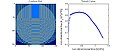
[edit]Solid rocket fuel deflagrates from the surface of exposed propellant in the combustion chamber. In this fashion, the geometry of the propellant inside the rocket motor plays an important role in the overall motor performance. As the surface of the propellant burns, the shape evolves (a subject of study in internal ballistics), most often changing the propellant surface area exposed to the combustion gases. Since the propellant volume is equal to the cross sectional area times the fuel length, the volumetric propellant consumption rate is the cross section area times the linear burn rate , and the instantaneous mass flow rate of combustion gases generated is equal to the volumetric rate times the fuel density :


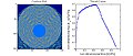
Several geometric configurations are often used depending on the application and desired thrust curve:
-
 Circular bore simulation
 -
 C-slot simulation
 -
 Moon burner simulation
 -
 5-point finocyl simulation


- Circular bore: if in BATES configuration, produces progressive-regressive thrust curve.
- End burner: propellant burns from one axial end to other producing steady long burn, though has thermal difficulties, center of gravity (CG) shift.
- C-slot: propellant with large wedge cut out of side (along axial direction), producing fairly long regressive thrust, though has thermal difficulties and asymmetric CG characteristics.
- Moon burner: off-center circular bore produces progressive-regressive long burn, though has slight asymmetric CG characteristics
- Finocyl: usually a 5- or 6-legged star-like shape that can produce very level thrust, with a bit quicker burn than circular bore due to increased surface area.
Casing
[edit]The casing may be constructed from a range of materials. Cardboard is used for small black powder model motors, whereas aluminium is used for larger composite-fuel hobby motors. Steel was used for the space shuttle boosters. Filament-wound graphite epoxy casings are used for high-performance motors.
The casing must be designed to withstand the pressure and resulting stresses of the rocket motor, possibly at elevated temperature. For design, the casing is considered a pressure vessel.
To protect the casing from corrosive hot gases, a sacrificial thermal liner on the inside of the casing is often implemented, which ablates to prolong the life of the motor casing.
Nozzle
[edit]A convergent-divergent design accelerates the exhaust gas out of the nozzle to produce thrust. The nozzle must be constructed from a material that can withstand the heat of the combustion gas flow. Often, heat-resistant carbon-based materials are used, such as amorphous graphite or reinforced carbon–carbon.
Some designs include directional control of the exhaust. This can be accomplished by gimballing the nozzle, as in the Space Shuttle SRBs, by the use of jet vanes in the exhaust as in the V-2 rocket, or by liquid injection thrust vectoring (LITV).
LITV consists of injecting a liquid into the exhaust stream after the nozzle throat. The liquid then vaporizes, and in most cases chemically reacts, adding mass flow to one side of the exhaust stream and thus providing a control moment. For example, the Titan IIIC solid boosters injected nitrogen tetroxide for LITV; the tanks can be seen on the sides of the rocket between the main center stage and the boosters.[18]
An early Minuteman first stage used a single motor with four gimballed nozzles to provide pitch, yaw, and roll control.
Performance
[edit]
A typical, well-designed ammonium perchlorate composite propellant (APCP) first-stage motor may have a vacuum specific impulse (Isp) as high as 285.6 seconds (2.801 km/s) (Titan IVB SRMU).[19] This compares to 339.3 s (3.327 km/s) for RP1/LOX (RD-180)[20] and 452.3 s (4.436 km/s) for LH2/LOX (Block II RS-25)[21] bipropellant engines. Upper stage specific impulses are somewhat greater: as much as 303.8 s (2.979 km/s) for APCP (Orbus 6E),[22] 359 s (3.52 km/s) for RP1/LOX (RD-0124)[23] and 465.5 s (4.565 km/s) for LH2/LOX (RL10B-2).[24]
Propellant fractions are usually somewhat higher for (non-segmented) solid propellant first stages than for upper stages. The 53,000-kilogram (117,000 lb) Castor 120 first stage has a propellant mass fraction of 92.23% while the 14,000-kilogram (31,000 lb) Castor 30 upper stage developed for Orbital Science's Taurus II COTS (Commercial Off The Shelf) (International Space Station resupply) launch vehicle has a 91.3% propellant fraction with 2.9% graphite epoxy motor casing, 2.4% nozzle, igniter and thrust vector actuator, and 3.4% non-motor hardware including such things as payload mount, interstage adapter, cable raceway, instrumentation, etc. Castor 120 and Castor 30 are 2.36 and 2.34 meters (93 and 92 in) in diameter, respectively, and serve as stages on the Athena IC and IIC commercial launch vehicles. A four-stage Athena II using Castor 120s as both first and second stages became the first commercially developed launch vehicle to launch a lunar probe (Lunar Prospector) in 1998.
Solid rockets can provide high thrust for relatively low cost. For this reason, solids have been used as initial stages in rockets (for example the Space Shuttle), while reserving high specific impulse engines, especially less massive hydrogen-fueled engines, for higher stages. In addition, solid rockets have a long history as the final boost stage for satellites due to their simplicity, reliability, compactness and reasonably high mass fraction.[25] A spin-stabilized solid rocket motor is sometimes added when extra velocity is required, such as for a mission to a comet or the outer solar system, because a spinner does not require a guidance system (on the newly added stage). Thiokol's extensive family of mostly titanium-cased Star space motors has been widely used, especially on Delta launch vehicles and as spin-stabilized upper stages to launch satellites from the cargo bay of the Space Shuttle. Star motors have propellant fractions as high as 94.6% but add-on structures and equipment reduce the operating mass fraction by 2% or more.
Higher performing solid rocket propellants are used in large strategic missiles (as opposed to commercial launch vehicles). HMX, C4H8N4(NO2)4, a nitramine with greater energy than ammonium perchlorate, was used in the propellant of the Peacekeeper ICBM and is the main ingredient in NEPE-75 propellant used in the Trident II D-5 Fleet Ballistic Missile.[26] It is because of explosive hazard that the higher energy military solid propellants containing HMX are not used in commercial launch vehicles except when the LV is an adapted ballistic missile already containing HMX propellant (Minotaur IV and V based on the retired Peacekeeper ICBMs).[27] The Naval Air Weapons Station at China Lake, California, developed a new compound, C6H6N6(NO2)6, called simply CL-20 (China Lake compound #20). Compared to HMX, CL-20 has 14% more energy per mass, 20% more energy per volume, and a higher oxygen-to-fuel ratio.[28] One of the motivations for development of these very high energy density military solid propellants is to achieve mid-course exo-atmospheric ABM capability from missiles small enough to fit in existing ship-based below-deck vertical launch tubes and air-mobile truck-mounted launch tubes. CL-20 propellant compliant with Congress' 2004 insensitive munitions (IM) law has been demonstrated and may, as its cost comes down, be suitable for use in commercial launch vehicles, with a very significant increase in performance compared with the currently favored APCP solid propellants. With a specific impulse of 309 s already demonstrated by Peacekeeper's second stage using HMX propellant, the higher energy of CL-20 propellant can be expected to increase specific impulse to around 320 s in similar ICBM or launch vehicle upper stage applications, without the explosive hazard of HMX.[29]
An attractive attribute for military use is the ability for solid rocket propellant to remain loaded in the rocket for long durations and then be reliably launched at a moment's notice.
Propellant families
[edit]Black powder (gunpowder) propellant
[edit]Black powder (gunpowder) is composed of charcoal (fuel), potassium nitrate (oxidizer), and sulfur (fuel and catalyst). It is one of the oldest pyrotechnic compositions with application to rocketry. In modern times, black powder finds use in low-power model rockets (such as Estes and Quest rockets),[30][31] as it is cheap and fairly easy to produce. The fuel grain is typically a mixture of pressed fine powder (into a solid, hard slug), with a burn rate that is highly dependent upon exact composition and operating conditions. The specific impulse of black powder is low, around 80 s (0.78 km/s). The grain is sensitive to fracture and, therefore, catastrophic failure. Black powder does not typically find use in motors above 40 newtons (9.0 pounds-force) thrust.
Zinc–sulfur (ZS) propellants
[edit]Composed of powdered zinc metal and powdered sulfur (oxidizer), ZS or "micrograin" is another pressed propellant that does not find any practical application outside specialized amateur rocketry circles due to its poor performance (as most ZS burns outside the combustion chamber) and fast linear burn rates on the order of 2 m/s. ZS is most often employed as a novelty propellant as the rocket accelerates extremely quickly leaving a spectacular large orange fireball behind it.
Double-base (DB) propellants
[edit]DB propellants are composed of two monopropellant fuel components where one typically acts as a high-energy (yet unstable) monopropellant and the other acts as a lower-energy stabilizing (and gelling) monopropellant. In typical circumstances, nitroglycerin is dissolved in a nitrocellulose gel and solidified with additives. DB propellants are implemented in applications where minimal smoke is required yet a medium-high Isp of roughly 235 s (2.30 km/s) is required. The addition of metal fuels (such as aluminium) can increase performance to around 250 s (2.5 km/s), though metal oxide nucleation in the exhaust can turn the smoke opaque.
Composite propellants
[edit]A powdered oxidizer and powdered metal fuel are intimately mixed and immobilized with a rubbery binder (that also acts as a fuel). Composite propellants are often either ammonium-nitrate-based (ANCP) or ammonium-perchlorate-based (APCP). Ammonium nitrate composite propellant often uses magnesium and/or aluminium as fuel and delivers medium performance (Isp of about 210 s (2.1 km/s)) whereas ammonium perchlorate composite propellant often uses aluminium fuel and delivers high performance: vacuum Isp up to 296 s (2.90 km/s) with a single-piece nozzle or 304 s (2.98 km/s) with a high-area-ratio telescoping nozzle.[22] Aluminium is used as fuel because it has a reasonable specific energy density, a high volumetric energy density, and is difficult to ignite accidentally. Composite propellants are cast, and retain their shape after the rubber binder, such as Hydroxyl-terminated polybutadiene (HTPB), cross-links (solidifies) with the aid of a curative additive. Because of its high performance, moderate ease of manufacturing, and moderate cost, APCP finds widespread use in space, military, and amateur rockets, whereas cheaper and less efficient ANCP finds use in amateur rocketry and gas generators. Ammonium dinitramide, NH4N(NO2)2, is being considered as a 1-to-1 chlorine-free substitute for ammonium perchlorate in composite propellants. Unlike ammonium nitrate, ADN can be substituted for AP without a loss in motor performance.
Polyurethane-bound aluminium-APCP solid fuel was used in the submarine-launched Polaris missiles.[32] APCP used in the space shuttle Solid Rocket Boosters consisted of ammonium perchlorate (oxidizer, 69.6% by weight), aluminium (fuel, 16%), iron oxide (a catalyst, 0.4%), polybutadiene acrylonitrile (PBAN) polymer (a non-urethane rubber binder that held the mixture together and acted as secondary fuel, 12.04%), and an epoxy curing agent (1.96%).[33][34] It developed a specific impulse of 242 seconds (2.37 km/s) at sea level or 268 seconds (2.63 km/s) in a vacuum. The 2005–2009 Constellation Program was to use a similar PBAN-bound APCP.[35]
In 2009, a group succeeded in creating a propellant of water and nanoaluminium (ALICE).
"Candy" propellants
[edit]In general, rocket candy propellants are an oxidizer (typically potassium nitrate) and a sugar fuel (typically dextrose, sorbitol, or sucrose) that are cast into shape by gently melting the propellant constituents together and pouring or packing the amorphous colloid into a mold. Candy propellants generate a low-medium specific impulse of roughly 130 s (1.3 km/s) and, thus, are used primarily by amateur and experimental rocketeers.
High-energy composite (HEC) propellants
[edit]Typical HEC propellants start with a standard composite propellant mixture (such as APCP) and add a high-energy explosive to the mix. This extra component usually is in the form of small crystals of RDX or HMX, both of which have higher energy than ammonium perchlorate. Despite a modest increase in specific impulse, implementation is limited due to the increased hazards of the high-explosive additives.
Composite modified double base propellants
[edit]Composite modified double base propellants start with a nitrocellulose/nitroglycerin double base propellant as a binder and add solids (typically ammonium perchlorate (AP) and powdered aluminium) normally used in composite propellants. The ammonium perchlorate makes up the oxygen deficit introduced by using nitrocellulose, improving the overall specific impulse. The aluminium improves specific impulse as well as combustion stability. High performing propellants such as NEPE-75 used to fuel the Trident II D-5 SLBM replace most of the AP with polyethylene glycol-bound HMX, further increasing specific impulse. The mixing of composite and double base propellant ingredients has become so common as to blur the functional definition of double base propellants.
Minimum-signature (smokeless) propellants
[edit]One of the most active areas of solid propellant research is the development of high-energy, minimum-signature propellant using C6H6N6(NO2)6 CL-20 nitroamine (China Lake compound #20), which has 14% higher energy per mass and 20% higher energy density than HMX. The new propellant has been successfully developed and tested in tactical rocket motors. The propellant is non-polluting: acid-free, solid particulates-free, and lead-free. It is also smokeless and has only a faint shock diamond pattern that is visible in the otherwise transparent exhaust. Without the bright flame and dense smoke trail produced by the burning of aluminized propellants, these smokeless propellants all but eliminate the risk of giving away the positions from which the missiles are fired. The new CL-20 propellant is shock-insensitive (hazard class 1.3) as opposed to current HMX smokeless propellants which are highly detonable (hazard class 1.1). CL-20 is considered a major breakthrough in solid rocket propellant technology but has yet to see widespread use because costs remain high.[28]
Electric solid propellants
[edit]Electric solid propellants (ESPs) are a family of high performance plastisol solid propellants that can be ignited and throttled by the application of electric current. Unlike conventional rocket motor propellants that are difficult to control and extinguish, ESPs can be ignited reliably at precise intervals and durations. It requires no moving parts and the propellant is insensitive to flames or electrical sparks.[36]
Hobby and amateur/model rocketry
[edit]Solid propellant rocket motors can be bought for use in model rocketry; they are normally small cylinders of black powder fuel with an integral nozzle and optionally a small charge that is set off when the propellant is exhausted after a time delay. This charge can be used to trigger a camera, or deploy a parachute. Without this charge and delay, the motor may ignite a second stage (black powder only).
In amateur rocketry, "candy" propellants are common because they offer relative safety and ease of production, ingredients that are readily available publicly, and a higher specific impulse than blackpowder motors.
In mid- and high-power rocketry, commercially made APCP motors are widely used. They can be designed as either single-use or reloadables. These motors are available in impulse ranges from "A" (1.26 Ns– 2.50 Ns) to "O" (20.48 kNs – 40.96 kNs), from several manufacturers. They are manufactured in standardized diameters and varying lengths depending on required impulse. Standard motor diameters are 13, 18, 24, 29, 38, 54, 75, 98, and 150 millimeters. Different propellant formulations are available to produce different thrust profiles, as well as special effects such as colored flames, smoke trails, or large quantities of sparks (produced by adding titanium sponge to the mix).
Use
[edit]Sounding rockets
[edit]Almost all sounding rockets use solid motors.
Missiles
[edit]Due to reliability, ease of storage and handling, solid rockets are used on missiles and ICBMs.
- Air-to-air missiles: AIM-9 Sidewinder, AIM-54 Phoenix, Fakour-90, Meteor, R-33, PL-15
- Ballistic missiles: Jericho, Sejjil, 9K720 Iskander, Fateh-110, ATACMS, DF-21
- ICBMs: LGM-30 Minuteman, UGM-133 Trident II, LGM-118 Peacekeeper, RT-2PM Topol, DF-41, M51 SLBM
Orbital rockets
[edit]Solid rockets are suitable for launching small payloads to orbital velocities, especially if three or more stages are used. Many of these are based on repurposed ICBMs.
Gravity-1 is the largest-payload-capacity rocket to get into orbit with only solid rocket motors.
Larger liquid-fueled orbital rockets often use solid rocket boosters to gain enough initial thrust to launch the fully fueled rocket.
- Delta II
- Titan IV
- Space Shuttle
- Space Launch System
- Ariane 5
- Atlas II
- Atlas V (optionally 1–5 boosters)
- Delta IV (optionally 2 or 4 boosters)
- H-IIA, H-IIB
- PSLV - optional solid boosters to lift heavier payloads
- GSLV Mk III
Solid fuel is also used for some upper stages, particularly the Star 37 (sometimes referred to as the "Burner" upper stage) and the Star 48 (sometimes referred to as the "Payload Assist Module", or PAM), both manufactured originally by Thiokol, and today by Northrop Grumman. They are used to lift large payloads to intended orbits (such as the Global Positioning System satellites), or smaller payloads to interplanetary—or even interstellar—trajectories. Another solid-fuel upper stage, used by the Space Shuttle and the Titan IV, was the Boeing-manufactured Inertial Upper Stage (IUS).
- Pioneer 10 and Pioneer 11 were both sent out of the Solar System by Star 37E upper stages from Atlas-Centaur rockets.
- Voyager 1 and Voyager 2 were both sent out of the Solar System by Star 37E upper stages from Titan IIIE rockets.
- Magellan was sent to Venus on an IUS after being deployed from Space Shuttle Atlantis on STS-30.
- Galileo was sent to Jupiter on an IUS after being deployed from Space Shuttle Atlantis on STS-34.
- Ulysses was sent to Jupiter on an IUS and a Star 48 PAM after being deployed from Space Shuttle Discovery on STS-41. It then was placed in a polar orbit around the Sun following a gravity assist around Jupiter.
- New Horizons was sent out of the Solar System on a Star 48 PAM from an Atlas V rocket.
Some rockets, like the Antares (manufactured by Northrop Grumman), have mandatory solid-fuel upper stages. The Antares rocket uses the Northrop Grumman-manufactured Castor 30 as an upper stage.
Advanced research
[edit]- Environmentally sensitive fuel formulations such as ALICE propellant
- Ramjets with solid fuel
- Variable thrust designs based on variable nozzle geometry
- Hybrid rockets that use solid fuel and throttleable liquid or gaseous oxidizer
See also
[edit]- Comparison of solid-fuelled orbital launch systems
- Comparison of orbital launch systems
- Comparison of orbital launcher families
- List of canceled launch vehicle designs
- List of missiles
- List of orbital launch systems
- List of sounding rockets
- List of military rockets
- Fireworks
- Pyrotechnic composition
- Intercontinental ballistic missile
- Jetex
- Space Shuttle Solid Rocket Booster
- Crawford burner
- Nano-thermite
- Skyrocket
References
[edit]- ^ chapters 1–2, Blazing the trail: the early history of spacecraft and rocketry, Mike Gruntman, AIAA, 2004, ISBN 1-56347-705-X.
- ^ Culler, Jessica (2015-06-16). "LADEE - Lunar Atmosphere Dust and Environment Explorer". NASA. Retrieved 2020-06-02.
- ^ "LockMart And ATK Athena Launch Vehicles Selected As A NASA Launch Services Provider". www.space-travel.com.
- ^ "Solid propellant rocket motor having self-extinguishing propellant grain and systems therefrom".
- ^ Hu, Wen-Rui (1997). Space Science in China. CRC Press (published August 20, 1997). p. 15. ISBN 978-9056990237.
- ^ a b Greatrix, David R. (2012). Powered Flight: The Engineering of Aerospace Propulsion. Springer. p. 1. ISBN 978-1447124849.
- ^ a b Nielsen, Leona (1997). Blast Off!: Rocketry for Elementary and Middle School Students P. Libraries Unlimited. pp. 2–4. ISBN 978-1563084386.
- ^ Van Riper, Bowdoin (2004). Rockets and Missiles: The Life Story of a Technology. The Johns Hopkins University Press. pp. 14–15. ISBN 978-0801887925.
- ^ Zak, Anatoly. "Gas Dynamics Laboratory". Russian Space Web. Retrieved 29 May 2022.
- ^ Glushko, Valentin (1 January 1973). Developments of Rocketry and Space Technology in the USSR. Novosti Press Pub. House. p. 7.
- ^ a b "Russian Rocket Projectiles – WWII". Weapons and Warfare. 18 November 2018. Retrieved 29 May 2022.
- ^ Akimov V.N.; Koroteev A.S.; Gafarov A.A. (2003). "The weapon of victory - "Katyusha"". Research Center named after M.V. Keldysh. 1933-2003 : 70 years at the forefront of rocket and space technology (in Russian). Мoscow: Scientific and technical publishing house "Mashinostroenie". pp. 92–101. ISBN 5-217-03205-7.
- ^ Zaloga, Steven J; James Grandsen (1984). Soviet Tanks and Combat Vehicles of World War Two. London: Arms and Armour Press. pp. 150–153. ISBN 0-85368-606-8.
- ^ Zak, Anatoly. "History of the Rocket Research Institute, RNII". Russian Spaceweb. Retrieved 18 June 2022.
- ^ M. D. Black (2012). The Evolution of Rocket Technology. Native Planter, SLC. p. 39. payloadz.com under ebook/History [dead link]
- ^ "The 260 - The Largest Solid Rocket Motor Ever Tested" (PDF). nasa.gov. June 1999. Retrieved July 24, 2014.
- ^ Kosanke, K. L.; Sturman, Barry T.; Winokur, Robert M.; Kosanke, B. J. (October 2012). Encyclopedic Dictionary of Pyrotechnics: (and Related Subjects). Journal of Pyrotechnics. ISBN 978-1-889526-21-8.
- ^ Sutton, George P. (2000). Rocket Propulsion Elements (7th ed.). Wiley-Interscience. ISBN 0-471-32642-9.
- ^ "ATK Space Propulsion Products Catalog, p.30" (PDF). Alliant Techsystems (ATK). May 2008. Archived from the original (PDF) on 30 July 2018. Retrieved 8 Dec 2015.
- ^ http://www.pw.utc.com/Products/Pratt+%26+Whitney+Rocketdyne/Propulsion+Solutions/Space[permanent dead link]
- ^ "Pratt & Whitney Rocketdyne". Archived from the original on 2011-04-26. Retrieved 2014-01-07.
- ^ a b "Titan IVB - Specifications". Archived from the original on 2013-07-19. Retrieved 2014-02-09.
- ^ http://www.russianspaceweb.com/engines/rd0124.htm [dead link]
- ^ "RL10B-2 brochure" (PDF). Pratt & Whitney Rocketdyne. 2009. Archived from the original (PDF) on 2012-03-26. Retrieved 2018-08-25.
- ^ Solid Archived 2002-01-05 at the Wayback Machine
- ^ Pike, John. "Trident II D-5 Fleet Ballistic Missile FBM / SLBM - United States". www.globalsecurity.org.
- ^ Minotaur IV User's Guide, Release 1.0, Orbital Sciences Corp., January 2005, p. 4
- ^ M. D. Black, The Evolution of ROCKET TECHNOLOGY, pp. 92-94, Native Planter, SLC, 2012, payloadz.com under ebook/History
- ^ "Model Rocketry Resources and Components". Retrieved 16 Aug 2017.
- ^ "Quest Black Powder Model Rocket Engines". Archived from the original on 16 August 2017. Retrieved 16 Aug 2017.
- ^ "Polaris A1 - United States Nuclear Forces".
- ^ "Shuttle Solid Rocket Boosters". NASA. Archived from the original on 2019-04-30. Retrieved 2015-10-02.
- ^ "Solid Rocket Boosters". NASA. Archived from the original on 2013-04-06. Retrieved 2015-10-02.
- ^ Chang, Kenneth (August 30, 2010). "NASA Tests Engine With an Uncertain Future". New York Times. Retrieved 2010-08-31.
- ^ Sawka, Wayne N.; McPherson, Michael (12 July 2013). "Electrical Solid Propellants: A Safe, Micro to Macro Propulsion Technology". 49th AIAA/ASME/SAE/ASEE Joint Propulsion Conference. American Institute of Aeronautics and Astronautics. doi:10.2514/6.2013-4168. ISBN 978-1-62410-222-6.
Further reading
[edit]- A. Davenas, ed. (1992). Solid Rocket Propulsion Technology. Pergamon. ISBN 978-0080409993.
External links
[edit]- Robert A. Braeunig rocket propulsion page
- Astronautix Composite Solid Propellants
- Ariane 5 SRB
- Amateur High Power Rocketry Association
- Nakka-Rocketry (Design Calculations and Propellant Formulations)
- 5 cent sugar rocket
- Practical Rocketry Archived 2006-06-18 at the Wayback Machine
- NASA Practical Rocketry
| Concepts | |||||||||
|---|---|---|---|---|---|---|---|---|---|
| Physical propulsion | |||||||||
| Chemical propulsion |
| ||||||||
| Electrical propulsion |
| ||||||||
| Nuclear propulsion |
| ||||||||
| External power | |||||||||
| Related concepts | |||||||||
| Liquid fuel |
|  | ||||||||||||||||
|---|---|---|---|---|---|---|---|---|---|---|---|---|---|---|---|---|---|---|
| Solid fuel |
| |||||||||||||||||
| ||||||||||||||||||
| International | |
|---|---|
| National | |
| Other | |
Solid-propellant rocket
View on GrokipediaA solid-propellant rocket is a rocket engine employing a solid composite propellant, consisting of a homogeneous mixture of fuel and oxidizer bound together and cast into a grain shape within a pressure vessel or casing, which upon ignition undergoes rapid combustion to generate high-velocity exhaust gases expelled through a converging-diverging nozzle for thrust production.[1] The fundamental components include the propellant grain, casing for containment, thermal insulation, igniter, and nozzle, rendering the system mechanically simple compared to liquid or hybrid variants.[2] Under ambient conditions, the propellant remains stable and non-reactive until deliberately ignited, at which point the burn proceeds uncontrollably until depletion due to the absence of separate feed systems or valves.[3] Originating from early pyrotechnic devices in 13th-century China utilizing black powder as propellant in arrow-like projectiles, solid-propellant technology advanced through military applications in warfare and evolved into high-performance motors for ballistic missiles, sounding rockets, and space launch boosters by the mid-20th century.[4] Notable implementations include strap-on boosters for heavy-lift vehicles, providing initial high-thrust impulses to overcome gravity, as seen in systems augmenting liquid-core stages for orbital insertion.[5] Key characteristics encompass high propellant density yielding compact designs with substantial thrust-to-weight ratios, long-term storability without cryogenic requirements, and operational simplicity facilitating rapid deployment in defense scenarios, though these come offset by challenges such as fixed burn profiles precluding throttling, shutdown, or precise vectoring absent auxiliary controls, alongside potential inefficiencies in specific impulse relative to optimized liquid bipropellants.[2][6] Empirical performance hinges on grain geometry—such as cylindrical, star, or finocyl configurations—to tailor burn rates and thrust curves via surface area regression, with modern composite propellants incorporating ammonium perchlorate oxidizer, aluminum fuel, and polymer binders achieving chamber pressures exceeding 100 atmospheres and effective exhaust velocities around 2.5 kilometers per second.[1]
Fundamentals
Operating Principles
A solid-propellant rocket motor consists of a casing containing a solid propellant grain, an igniter, and a nozzle. The propellant grain is a cast or extruded mixture of fuel, oxidizer, and binder, forming a solid mass with predefined geometry to control burning characteristics.[1] Upon activation, the igniter generates hot gases or particles that initiate combustion at the exposed surfaces of the grain, typically raising chamber pressure above 4 MPa for sustained burning in composite propellants.[7] Combustion proceeds as a deflagration wave normal to the burning surface, regressing inward at a rate governed by Vieille's law: , where is the linear burn rate, is chamber pressure, is a temperature-dependent coefficient, and is the pressure exponent (typically 0.2–0.6 for stable operation).[7] [8] The burning surface area evolves with grain geometry, influencing the mass generation rate , where is propellant density; this balances exhaust flow through the nozzle throat to maintain quasi-equilibrium pressure.[7] Hot combustion products, reaching temperatures of 2000–3500 K, expand through the convergent-divergent nozzle, accelerating to supersonic velocities at the exit to produce thrust via , where is exit velocity, and are exit and ambient pressures, and is exit area.[1] The nozzle throat chokes the flow at Mach 1, coupling grain regression to thrust profile; once ignited, the motor cannot be throttled or extinguished, delivering fixed-duration impulse determined by total propellant mass and specific impulse (typically 200–300 seconds).[1][7]Advantages and Limitations
Solid-propellant rockets offer simplicity in design due to the absence of turbopumps, cryogenic storage requirements, and complex plumbing systems associated with liquid propellants, resulting in fewer moving parts and reduced potential failure points.[9][10] This configuration enables rapid readiness for launch, often with minimal preparation time, making them suitable for applications requiring immediate response, such as missile defense systems.[11] Additionally, their high propellant density allows for compact, high-thrust output, with thrust-to-volume ratios superior to many liquid systems, facilitating efficient booster stages in launch vehicles.[12][13] These motors exhibit excellent long-term storability, with propellants maintaining stability for years without significant degradation, unlike liquids that may require ongoing maintenance to prevent leaks or boiling.[9][11] The integrated oxidizer-fuel mixture ensures reliable ignition and operation in vacuum environments, as no external oxygen source is needed.[1] Overall reliability stems from the structural integrity of the propellant grain, which doubles as the combustion chamber, providing inherent strength under high pressure.[6] Key limitations include the inability to throttle, restart, or shut down the engine post-ignition, as combustion proceeds uncontrollably until propellant depletion, restricting mission flexibility compared to liquid systems.[14][12] Specific impulse values typically range from 250 to 300 seconds for solids, lower than the 300-450 seconds achievable with advanced liquid bipropellants like liquid hydrogen and oxygen, leading to reduced propellant efficiency for upper stages or sustained burns.[15][16] Safety concerns arise from the high explosion risk during handling or storage of fully loaded motors, compounded by potential for accidental ignition and the production of toxic exhaust plumes containing aluminum oxides and hydrochloric acid.[14] Propellant grains have finite shelf lives, often 5-10 years before degradation risks increase, necessitating periodic replacement or testing.[14] Manufacturing complexity in achieving uniform grain geometries for controlled burn rates can introduce defects, potentially causing catastrophic failures, though mitigated by rigorous quality controls.[17]Historical Development
Pre-20th Century Origins
The development of solid-propellant rockets originated in China with the invention of gunpowder, a mixture of approximately 75% saltpeter, 15% charcoal, and 10% sulfur, formulated by Tang Dynasty alchemists around 850 AD for alchemical experiments. This black powder, when confined and ignited, produced sustained thrust through deflagration, enabling early pyrotechnic devices like fireworks by the 10th century. Military adaptation followed, transitioning from fire lances—bamboo tubes spewing flame—to propelled projectiles, with gunpowder serving as the self-contained solid propellant that required no external oxidizer beyond its own composition.[18][19] The first documented rockets appeared during the Song Dynasty in 1232 AD, when Chinese defenders at Kaifeng used "arrows of flying fire" against Mongol invaders led by Ögedei Khan. These consisted of gunpowder-packed bamboo casings attached to arrows, achieving propulsion via internal combustion that expelled gases through a rear orifice, with ranges estimated at several hundred meters for incendiary or explosive payloads. Historical texts like the Wujing Zongyao (1044 AD) describe precursor formulas, but battlefield records from the Kaifeng siege confirm operational deployment, highlighting gunpowder's role in providing reliable, portable thrust independent of weather or barrel mechanisms. Rocketry knowledge disseminated via Mongol conquests to the Middle East by the 13th century, where Arabic manuscripts detailed similar black powder devices for siege warfare, though without major propellant innovations until later centuries.[20][19] In the 18th century, significant refinements occurred in the Kingdom of Mysore, India, under Hyder Ali (r. 1761–1782) and Tipu Sultan (r. 1782–1799), who organized rocket corps employing iron-cased black powder rockets. These featured welded iron tubes up to 150 mm diameter and 2 meters long, filled with propellant and fitted with sword blades for anti-personnel effects, attaining ranges of 1–2 km—superior to contemporary European artillery due to the casing's ability to withstand higher chamber pressures without bursting. Approximately 1,200 such rockets were captured by British forces after the 1799 Siege of Seringapatam, demonstrating their tactical efficacy in the Anglo-Mysore Wars, where they disrupted infantry formations through psychological impact and area saturation.[21] European adoption accelerated with Sir William Congreve's designs in Britain, directly inspired by dissected Mysorean specimens. By 1805, Congreve produced stick-stabilized rockets in calibers from 3 to 32 pounds, using refined black powder for velocities up to 150 m/s and ranges exceeding 3 km in light variants. First combat-tested against French ships at Boulogne in 1806, these solid-propellant weapons emphasized simplicity and mass production, influencing naval and land barrages during the Napoleonic Wars and the 1812 invasion of the United States, though accuracy remained limited by unguided flight paths. Pre-20th century solid rocketry thus evolved from empirical black powder applications, prioritizing storability and ease of ignition over precision, with causal limitations tied to propellant's low specific impulse (around 80 seconds) from incomplete combustion.[18][22]World Wars and Early Military Applications
During World War I, solid-propellant rocket development for military purposes remained experimental and limited in scale. Robert H. Goddard conducted early work on solid fuels starting in 1915, measuring exhaust velocities and advancing designs. By 1918, he developed several types of solid-fuel rockets suitable for firing from hand-held or tripod-mounted launching tubes, culminating in a demonstration of a tube-launched solid-propellant rocket on November 7, 1918, using a music stand as the platform. These efforts laid groundwork for portable rocket weapons but saw no widespread deployment amid the war's focus on established artillery.[18][23][24] World War II marked the first large-scale military applications of solid-propellant rockets, driven by their advantages in simplicity, rapid deployment, and storability without cryogenic fuels. The Soviet Union introduced the Katyusha (BM-13) multiple rocket launcher in July 1941, employing M-13 rockets with solid propellant derived from double-base formulations like ballistite, achieving ranges of approximately 8.5 kilometers and delivering high-explosive warheads in saturating barrages. These unguided rockets, stabilized by spin, prioritized volume of fire over precision, with launchers firing salvos of 16 rockets in seconds from truck-mounted rails. Similar systems proliferated, including German Nebelwerfer rocket artillery using solid propellants for indirect fire support.[25][26] In the United States, the M1 Bazooka, fielded in 1942, represented an early man-portable anti-tank weapon powered by the M6 solid-propellant rocket, which used a double-base propellant of nitrocellulose and nitroglycerin to propel a shaped-charge warhead to speeds of 82 m/s over effective ranges up to 150 meters. This electrically ignited system allowed infantry to engage armored vehicles without recoil, though early models suffered from reliability issues in humid conditions. Concurrently, Jet-Assisted Take-Off (JATO) units, such as Aerojet's solid-fuel motors producing 1,000 pounds of thrust for 15 seconds, aided overloaded aircraft launches from short runways, with initial tests in 1941 enabling broader operational flexibility for bombers and fighters. Millions of solid-propellant rockets were produced across Allied and Axis forces for barrage, anti-tank, and aviation roles, compensating for inaccuracy with sheer quantity and ease of production using extruded propellant grains.[27][28][29][26]Cold War and Space Race Advancements
The United States accelerated solid-propellant rocket development in the 1950s amid escalating Cold War tensions and fears of a Soviet missile advantage, prioritizing storable, quick-response systems over complex liquid-fueled alternatives. The Navy's Polaris program, launched in 1956, yielded the UGM-27A Polaris A1, the first operational submarine-launched ballistic missile (SLBM) with solid-propellant stages, achieving fleet deployment in 1960 after initial tests in 1958. Powered by two Aerojet-General solid-fuel motors using composite propellants, the Polaris provided submerged launch capability with thrust-vector control via jetevators, enabling a range of approximately 2,200 kilometers and reducing preparation time to minutes compared to liquid systems requiring fueling. This breakthrough stemmed from advances in filament-wound fiberglass casings and high-energy ammonium perchlorate-based composites, which improved specific impulse and reliability for naval applications.[30][31] Concurrently, the Air Force pursued the LGM-30 Minuteman intercontinental ballistic missile (ICBM), authorized in 1958 following Colonel Edward N. Hall's advocacy for solid fuels to enable silo-based rapid retaliation. The three-stage Minuteman I, with motors from Thiokol and Hercules Powder Company, entered operational service in 1962, boasting a 13,000-kilometer range, high storability, and launch readiness under 1 minute; over 1,000 silos were deployed by the mid-1960s. Propellant innovations, including aluminized composites yielding specific impulses around 260 seconds, addressed early challenges like grain cracking and thrust tail-off, enhancing survivability against preemptive strikes. These systems supplanted liquid ICBMs like Atlas, which suffered from cryogenic handling vulnerabilities.[32][33] In the Space Race, solid propellants facilitated affordable, reliable access to orbit via the Scout launch vehicle, developed by NASA and the Navy from 1959 using surplus missile components. The all-solid four-stage Scout achieved its first successful orbital insertion in 1960 with Explorer S-46, launching small payloads up to 200 kilograms into low Earth orbit at costs far below liquid alternatives, supporting over 110 missions through the 1990s for scientific satellites and technology tests. This leveraged missile-era motors like Algol and Antares, demonstrating solids' simplicity for non-heavy-lift roles without fueling infrastructure.[34][35] Soviet solid-propellant progress trailed, with emphasis on liquid engines for heavy-lift like the R-7; large-scale solids faced scaling issues in propellant uniformity and casing integrity. The RT-2 (SS-13 Savage), the USSR's inaugural solid-fueled ICBM, underwent development from 1961 and achieved initial deployment around 1969 as a three-stage system with a 10,000-kilometer range, but production was limited compared to U.S. volumes due to technical hurdles and strategic preferences for storable liquids. Espionage attempts to acquire U.S. composite formulations underscored the gap, though Soviet efforts intensified post-1960s for SLBMs like the R-31.[36][37]Post-1990 Developments
The Reusable Solid Rocket Motor (RSRM), derived from the Redesigned Solid Rocket Motor post-Challenger disaster, underwent iterative improvements from the early 1990s through 2011 to enhance reliability, reduce manufacturing costs, and address obsolescence. Between the mid-1990s and early 2000s, over 100 materials in the RSRM became obsolete due to environmental regulations and supply chain issues, necessitating substitutions such as non-asbestos insulation and updated adhesives while maintaining structural integrity and performance margins.[38] These upgrades included refined joint designs to minimize rotation and leakage risks during ignition, advanced filament-wound carbon composite cases for lighter weight, and optimized propellant grain geometries for neutral burn profiles, enabling the motors to support 133 Space Shuttle missions with a thrust of approximately 1.2 million kgf each.[38][39] ![Space Shuttle Columbia launching.jpg][float-right] Transitioning from the Shuttle program, the Space Launch System (SLS) incorporated five-segment solid rocket boosters (SRBs) starting in development around 2011, extending the four-segment RSRM design by adding a forward segment for 25% greater propellant volume and thrust exceeding 1.5 million kgf per booster. NASA and Orbital ATK (now Northrop Grumman) conducted four full-scale development motor static firings between 2014 and 2016 at Utah's Promontory facility, validating segmented case construction, hydroxyl-terminated polybutadiene (HTPB)-based composite propellant, and enhanced nozzles with carbon-carbon throats for erosion resistance.[40][41] These boosters powered the SLS Block 1 core stage in the Artemis I uncrewed test flight on November 16, 2022, delivering a total liftoff thrust of 3.6 million kgf combined with core engines. Ongoing Booster Obsolescence and Life Extension (BOLE) efforts, initiated in 2019, aim to replace legacy components with modern composites and processing for sustained production beyond 2025, though a June 2025 test of a BOLE-derived motor segment encountered an anomaly, prompting investigations into joint pressurization.[42] Military applications saw refinements in solid motors for intercontinental ballistic missiles and tactical systems, including the U.S. Minuteman III life-extension programs from the 1990s onward, which incorporated insensitive munitions-compliant propellants and improved guidance integration without altering core thrust profiles of 90,000 kgf. Internationally, Europe's Ariane 5 employed P230 solid boosters with 525 metric tons of propellant each, debuting on June 4, 1996, and enabling 117 launches through 2023 by optimizing star-grain configurations for high mass fractions above 0.90. China's Gravity-1 vehicle, utilizing three large solid boosters, achieved its first orbital success on January 11, 2024, demonstrating scalable clustered designs with over 100 tons of propellant per core for commercial small-satellite deployment.[43] Advancements in simulation and materials post-1990 enabled precise modeling of erosive burning and grain regression, reducing development costs; for instance, computational fluid dynamics integrated with empirical burn-rate data improved predictions for complex geometries like finocyl slots, as applied in SLS qualification. These efforts prioritized causal factors such as propellant density (around 1,780 kg/m³ for HTPB/AP/AL formulations) and chamber pressure (6-7 MPa) to mitigate anomalies like thrust tail-off, with peer-reviewed validations confirming enhanced reliability over legacy black powder or double-base propellants.[44]Design and Components
Propellant Grain Configuration
The propellant grain configuration in a solid-propellant rocket motor defines the geometry of the cast or extruded propellant charge, which governs the temporal evolution of the burning surface area and thus the mass generation rate , where is the propellant density and is the linear burn rate. This design is critical for tailoring the motor's thrust-time curve to mission requirements, balancing ballistic performance against structural integrity constraints such as stress concentrations at port features or case bonds.[45] Geometries are selected to produce neutral (constant ), progressive (increasing ), or regressive (decreasing ) burning profiles, with internal-burning configurations predominant due to their flexibility in exposing larger initial surfaces compared to end-burning types.[45] End-burning grains expose combustion only on one forward face, with the aft and lateral surfaces inhibited by liners, resulting in a constant equal to the grain's cross-sectional area and a neutral thrust profile throughout the burn duration.[45] This simplicity suits short-length motors or applications needing predictable, low-variability thrust, such as certain missile sustainers, but limits initial thrust magnitude and total impulse due to minimal exposed area; advancements in high-burn-rate propellants and compliant inhibitors have enabled scaling to larger motors.[45] Structural analysis for end-burners emphasizes bulk propellant properties under axial constraints, as radial expansion is restricted by the casing, potentially inducing tensile stresses during cooldown or pressurization.[45] Internal-burning grains, cast with a central port of engineered cross-section, initiate combustion along the port walls and progress radially outward, offering greater surface area control for high-thrust boosters.[45] Simple cylindrical ports yield approximately progressive burning, as increases with port diameter over time (where is grain length), though end effects and inhibitors modulate this; they are cost-effective but prone to cracking at the evolving free surface.[45] More complex geometries, such as finocyl (cylindrical core with peripheral fins) or star-shaped ports, enhance initial via protrusions that regress to expose additional area, enabling tailored progressive profiles for staged acceleration—as in space launch boosters—while finite-element stress modeling mitigates vulnerabilities like fin-tip fractures under dynamic loads.[45] External-internal hybrids further amplify by burning both inward from the case and outward from a core port, but demand robust internal supports to endure gas flows, limiting their use to specialized high-impulse designs.[45] Cartridge-loaded grains, pre-cast externally and inserted into the case (bonded or free-standing), facilitate manufacturing of intricate geometries but introduce risks from dynamic interactions, such as slippage under acceleration, necessitating precise alignment and inhibition.[45] Overall, grain design iterates via ballistic simulation and structural finite-element analysis to ensure integrity, with port features like slots or moons optimized to avoid erosive burning or sliver residues that reduce efficiency.[45]Casing Structure
The casing of a solid-propellant rocket motor functions as a high-pressure containment vessel, enclosing the propellant grain while resisting internal combustion pressures typically ranging from 500 to 10,000 psi and temperatures exceeding 2,000°C in the chamber.[17] It must maintain structural integrity throughout the burn duration, often seconds to minutes, to prevent catastrophic failure, and contributes to the motor's overall thrust structure by transmitting loads to the airframe or payload.[46] Design emphasizes thin-walled cylindrical geometry to minimize weight, with hoop stresses governed by formulas such as σ = P r / t, where P is chamber pressure, r is radius, and t is wall thickness, requiring safety factors of 1.25 to 2.0 against burst pressure.[17] End closures, typically hemispherical or ellipsoidal domes, handle longitudinal stresses and are integrated via welding or bonding to ensure leak-proof seals.[47] Traditional casings employ metallic alloys such as high-strength low-alloy steels (e.g., AISI 4130 or 4340), aluminum-lithium alloys, or titanium for their ductility, weldability, and ability to endure cyclic pressures without brittle fracture.[46] Steel casings, common in early motors like those from the 1950s Polaris program, offer cost-effective fabrication via forging, rolling, and electron-beam welding, with yield strengths up to 1,000 MPa, though they add mass that reduces specific impulse.[47] [17] Advanced metals like Inconel superalloys provide superior creep resistance at elevated temperatures, suitable for reusable or high-thrust applications, but at higher material costs.[46] Contemporary designs favor filament-wound composite overwrapped pressure vessels (COPVs) using carbon fiber reinforced polymers (CFRP) or Kevlar/epoxy systems, achieving stiffness-to-weight ratios 3-5 times higher than metals, which enables payload fractions up to 10-15% greater in space launch vehicles.[48] [49] These structures layer helical and hoop windings to optimize fiber orientation against principal stresses, with epoxy matrices providing interlaminar shear strength; for instance, the Space Shuttle's solid rocket boosters used steel liners overwrapped with composites for hybrid benefits.[50] Composites reduce inert mass by 30-50% compared to equivalent steel casings but demand precise cure cycles in autoclaves to avoid voids, and they incorporate metallic liners or polar bosses for interfaces with nozzles and igniters.[51] Manufacturing tolerances must limit defects to under 1% porosity to prevent delamination under hydrostatic testing at 1.5 times design pressure.[48] Internal liners and thermal barriers, such as EPDM rubber or silica-filled elastomers bonded to the casing, mitigate heat transfer, limiting casing temperatures to 200-500°C to preserve material properties; without them, steel strength drops 20-50% at 300°C due to yield stress reduction.[52] [17] Joints and seams undergo non-destructive testing like ultrasonic inspection to detect flaws, ensuring reliability rates exceeding 99.9% in flight-proven motors.[46] Design trade-offs balance pressure containment with buckling resistance under external loads, often verified via finite element analysis incorporating anisotropic properties for composites.[51]Nozzle Engineering
The nozzle in a solid-propellant rocket motor functions as the converging-diverging (de Laval) structure at the aft end of the combustion chamber, accelerating high-temperature exhaust gases from subsonic to supersonic velocities to generate thrust via momentum transfer.[53] The converging section reduces flow area to achieve sonic conditions (Mach 1) at the minimum throat area , while the diverging section expands the flow isentropically to the exit area , converting thermal energy into directed kinetic energy and minimizing exhaust pressure relative to ambient pressure for optimal specific impulse .[53] In solid motors, nozzles are fixed and non-throttleable, with throat diameter sized to maintain desired chamber pressure via the relation , where is the propellant burning surface area, ensuring stable combustion without overpressurization.[54] The expansion ratio is a critical design parameter, typically ranging from 5 to 20 for solid motors depending on operational altitude; sea-level launches favor lower ratios (e.g., ) to avoid flow separation and thrust loss from overexpansion, while vacuum-optimized nozzles use higher ratios (e.g., ) for greater exhaust velocity , where is chamber temperature, specific heat, and the gas specific heat ratio.[55] Conical divergent sections predominate in solid rocket nozzles for manufacturability, though they incur 5-10% divergence losses compared to parabolic contours; the half-angle is often 12-15° to balance efficiency and length.[53] Throat erosion from thermochemical reactions with propellant combustion products (e.g., alumina particles in aluminized formulations) enlarges over burn time, reducing by up to 20-30% in long-duration motors and degrading unless compensated by initial oversizing.[56] Materials selection prioritizes ablation resistance under temperatures exceeding 3000 K and oxidative environments; carbon-phenolic composites serve as primary ablative liners, charring and eroding at controlled rates (0.1-0.5 mm/s) to form a protective boundary layer, while graphite or carbon-carbon throats provide structural integrity up to 1-2 MPa shear stress from particle impingement.[57] Silica-reinforced phenolics enhance erosion resistance in throats, with tests showing reduced mass loss under high-velocity flows relative to unreinforced variants. No regenerative cooling is feasible due to the fixed propellant grain, necessitating passive thermal protection; advanced designs incorporate radiation-cooled metallic extensions (e.g., niobium alloys) for exit cones in reusable motors, though ablation remains the dominant heat management mechanism, limiting nozzle lifetimes to single-use in most tactical and launch applications.[59] Finite-rate chemistry models predict erosion depths, informing iterative designs to maintain thrust profiles within 5% deviation over burn durations up to 120 seconds.[57]Ignition and Control Systems
Ignition of solid-propellant rocket motors typically relies on pyrotechnic devices that generate high-temperature gases or particles to initiate combustion across the propellant grain surface. These igniters, often consisting of compositions like boron/potassium nitrate or other fast-burning pyrotechnics, are electrically initiated and produce a rapid pressure rise to ensure uniform ignition and avoid hangfires or incomplete burns.[60][61] For larger motors, such as those in space launch vehicles, pyrogen igniters—small auxiliary solid rockets—provide sustained hot gas flow to pressurize the chamber and ignite the main propellant reliably.[62] In the Space Shuttle Solid Rocket Boosters (SRBs), ignition begins with an electrical signal firing a pyrotechnic initiator, which ignites a booster charge behind a perforated plate; this in turn activates the main through-bulkhead igniter assembly, delivering pressurized combustion products into the motor chamber to achieve full ignition within milliseconds.[63] Alternative methods, such as hypergolic fluid injection, have been explored for specialized applications but are less common due to complexity and safety concerns compared to pyrotechnics.[64] Control systems for solid-propellant rockets are inherently limited by the propellant’s irreversible combustion once ignited, precluding throttling or shutdown except through destructive means. Primary steering is achieved via thrust vector control (TVC), with gimbaled nozzles using flexible joints or seals allowing ±5 to ±10 degrees of deflection, actuated by hydraulic or electromechanical systems to direct thrust for trajectory corrections.[65] Liquid injection TVC, injecting fluids like nitrogen tetroxide into the nozzle to asymmetrically deflect exhaust, offers a non-mechanical alternative but introduces mass penalties and erosion risks.[65] [66] For attitude control in upper stages or missiles, jet vanes—retractable aerodynamic surfaces in the exhaust plume—provide vectored thrust, as demonstrated in historical designs enduring high thermal loads up to 3000 K.[67] Thrust termination, critical for range safety, employs pyrotechnic ports or linear shaped charges to rupture the casing or nozzle, venting combustion products and nullifying net thrust; this reduces velocity by dispersing propellant burn without full explosion, as in flight termination systems (FTS) that activate on command to comply with downrange limits.[68][69] Such systems ensure termination within seconds, though residual burning persists until propellant depletion.[70]Propellant Formulations
Early and Simple Propellants
The earliest solid propellants for rockets were based on black powder, a mechanical mixture of potassium nitrate (75%), charcoal (15%), and sulfur (10%) by weight, discovered in China during the 9th century AD and first applied to rocketry by the 13th century for military fire arrows during conflicts such as the Mongol invasions.[5][71] This propellant functioned through rapid surface combustion, producing gases that generated thrust via nozzle expansion, but its low specific impulse (around 80-100 seconds) and inconsistent burn rates limited performance due to heterogeneous particle sizes and sensitivity to packing density.[4] Black powder's simplicity—requiring no advanced synthesis—enabled widespread use in early European adaptations, such as the Congreve rockets developed by British engineer William Congreve around 1804, which employed iron casings filled with approximately 1 pound of compacted black powder to achieve ranges up to 3,000 yards in naval and land warfare.[72][73] By the late 19th century, limitations in black powder's energy density and smoke production prompted development of homogeneous propellants, starting with single-base formulations of nitrocellulose (NC) dissolved in solvents and extruded into grains, offering higher stability and burn control than black powder mixtures.[74] These evolved into double-base propellants, pioneered by Alfred Nobel's ballistite in 1887, comprising roughly 60% nitrocellulose gelatinized with 40% nitroglycerin (NG) without additional solvents like camphor in later variants, providing a self-contained fuel-oxidizer system with improved specific impulse (up to 200 seconds) and reduced residue.[31] Double-base propellants burned progressively from the grain surface, enabling predictable thrust via geometric shaping, and were cast or extruded for reliability in early 20th-century applications, though their hygroscopic nature and vulnerability to cracking under temperature swings posed challenges absent in simpler black powder.[75] These early formulations laid the groundwork for solid rocketry by emphasizing deflagration over detonation, with black powder's empirical trial-and-error refinement giving way to double-base's chemical uniformity, yet both suffered from lower energy release compared to later composites due to incomplete oxidation and limited molecular oxygen content.[76] Early testing, such as Congreve's standardized powder compositions, demonstrated causal links between grain density and velocity, achieving muzzle velocities around 300-400 m/s, underscoring the need for precise manufacturing to mitigate variability.[77] Double-base adoption accelerated in World War II for jet-assisted take-off (JATO) units, where extruded grains replaced black powder's irregularity, marking a shift toward scalable, higher-performance simplicity before composite innovations.[74]Composite Propellants
Composite propellants represent a major advancement in solid rocket propulsion, characterized by a heterogeneous mixture of a polymeric binder serving as fuel and structural matrix, embedded with solid oxidizer crystals and metallic fuel particles. This formulation enables high-energy, castable propellants with controllable burning rates and superior specific impulse compared to earlier homogeneous types.[78][26] The standard composition features ammonium perchlorate (AP) as the primary oxidizer, comprising 60-75% by weight, which supplies oxygen for combustion while maintaining chemical stability and high density. Aluminum powder, typically 15-20% by weight, acts as the metallic fuel, releasing additional heat through exothermic oxidation and boosting specific impulse by 20-30 seconds over non-metallized variants. The binder, often hydroxyl-terminated polybutadiene (HTPB) at 10-15% by weight, provides mechanical integrity, low-temperature flexibility, and acts as a secondary fuel; HTPB's diene structure allows curing via addition reactions for consistent viscoelastic properties. Additives such as burn-rate catalysts (e.g., iron oxide) and plasticizers fine-tune regression rates and processability.[26][79][80] Development of composite propellants accelerated during World War II, with early castable variants emerging in 1942 using asphalt as binder and potassium perchlorate as oxidizer, though these suffered from low performance and poor aging. Post-war refinements in the 1950s introduced polyester and polyurethane binders with AP, enabling larger motors for missiles like Polaris. By the mid-1960s, HTPB binders were formulated, offering improved pot life, tensile strength exceeding 1 MPa, and elongation over 200%, which facilitated high-volume production for programs such as Minuteman and the Space Shuttle's solid rocket boosters. These propellants achieve chamber pressures of 5-10 MPa and specific impulses of 250-270 seconds at sea level, with burning rates modulated from 5-20 mm/s via AP bimodal particle sizing (e.g., 200 μm coarse and 5-20 μm fine fractions).[76][80][71] Combustion in composite propellants proceeds via a diffusion-flame mechanism at the binder-oxidizer interface, where AP decomposes endothermically to release ammonia and perchloric acid, igniting the aluminum and binder pyrolysis products in a premixed zone; this yields plateau or mesa burning behaviors for thrust tailoring. Vulnerabilities include aluminum agglomeration, forming particles up to 100 μm that reduce efficiency by 5-10% if not mitigated through graded particle distributions. Environmental concerns arise from HCl emissions (up to 20% of exhaust mass), prompting research into alternatives like ADN oxidizers, though AP/HTPB/Al remains dominant due to proven reliability in over 10,000 motors annually.[79][81]High-Energy and Specialized Variants
High-energy solid propellants incorporate advanced energetic materials such as nitramines like hexogen (RDX) or octogen (HMX) into composite formulations to elevate specific impulse (Isp) beyond standard ammonium perchlorate (AP)/hydroxyl-terminated polybutadiene (HTPB) systems, which typically achieve around 260 seconds in vacuum. For instance, a binder-amine aluminum borohydride (BAAB)-based formulation with 18% aluminum and 18.5% RDX yields an Isp of 275.45 seconds, demonstrating enhanced performance through higher energy density from the nitramine additives.[82] Similarly, low-level incorporation of 2,4,6,8,10,12-hexanitrohexaazaisowurtzitane (CL-20) into booster or orbit transfer propellants significantly boosts overall Isp without requiring full replacement of conventional oxidizers, as CL-20's high detonation velocity and density contribute to superior combustion efficiency.[83] These variants prioritize raw energetic output but often necessitate careful mechanical property tuning to mitigate sensitivity issues.[84] Specialized green propellants replace AP with oxygen-balanced oxidizers like ammonium dinitramide (ADN) to eliminate hydrochloric acid emissions, offering comparable or higher Isp potential—up to 260 seconds or more in ADN/glycidyl azide polymer (GAP) systems—while producing primarily nitrogen, water, and carbon dioxide.[85] A 3-kilogram ADN/GAP motor was successfully test-fired, confirming operational viability, though ADN's hygroscopicity demands specialized processing.[86] Burn rates in ADN propellants can exceed those of AP equivalents, further doubled via metallic fiber additives for booster applications.[87] Other high-energy oxidizers, such as 2,2,2-trinitroethyl-formate (TNEF) in HTPB binders, achieve burn rates of 12.11 mm/s (14% higher than AP/HTPB at 10.64 mm/s) with an Isp of 251.2 seconds, serving as AP substitutes in environmentally constrained scenarios.[82] Advanced binder systems enhance specialization, including energetic polymers like GAP (density 1.30 g/cm³, formation enthalpy 117 kJ/mol) or poly(3,3-bisazidomethyl oxetane) (PBAMO), which integrate azide groups for increased heat of explosion in composite-modified double-base propellants.[82] Oxygen-enriched thermoplastic elastomer binders, such as polyether-block-amide (PEBA), provide mechanical advantages over HTPB, including improved aging and lower costs, while maintaining comparable burn rates influenced by AP particle size.[88] Electric solid propellants represent a control-oriented variant, formulated to ignite, throttle, and extinguish via applied electric fields rather than pyrotechnics, enabling precise thrust modulation in applications demanding variable performance; NASA evaluations in 2019 highlighted their potential for hybrid-like controllability in chemical solid matrices.[89] These formulations, often blending traditional composites with conductive additives, prioritize operational flexibility over peak energy density.Performance Metrics
Thrust Profile and Efficiency
The thrust profile of a solid-propellant rocket motor is inherently fixed once ignited, governed primarily by the propellant grain's geometry, which controls the temporal variation in burning surface area. Combustion proceeds radially inward from the exposed surface at a burn rate influenced by local pressure, temperature, and propellant composition, with thrust proportional to the product of chamber pressure and nozzle throat area.[90] Grain designs are engineered to yield specific profiles: regressive burning, where surface area decreases (e.g., in end-burning or simple cylindrical ports, leading to declining thrust suitable for initial boost phases); neutral burning, maintaining constant surface area for steady thrust (e.g., via parallel slots or certain core shapes); and progressive burning, where surface area increases over time (e.g., star or finocyl configurations exposing more propellant as outer layers regress).[91] [6] These profiles enable tailored mission requirements, such as high initial acceleration followed by sustainment, though deviations can arise from erosive burning—accelerated regression due to high-velocity core flow—or manufacturing imperfections. Efficiency in solid motors is quantified by specific impulse (Isp), defined as thrust divided by the weight flow rate of propellant (Isp = F / (ṁ ⋅ g0), measuring exhaust velocity effectiveness.[92] Typical vacuum Isp values range from 250 to 300 seconds for composite propellants, reflecting dense packing and heterogeneous combustion that limits complete energy release compared to homogeneous liquid systems.[93] This lower efficiency stems from causal factors including incomplete mixing of oxidizer and fuel particles, fixed stoichiometry without real-time adjustment, and sensitivity to pressure-dependent burn rates that can reduce characteristic velocity (c*).[94] Optimized designs mitigate losses through high chamber pressures (up to 100 atm), efficient nozzle expansion ratios, and propellant formulations maximizing energy density and minimizing two-phase flow penalties from solid particulates in exhaust.[45] Grain geometry not only shapes thrust but intersects with efficiency via structural integrity and burn uniformity; complex profiles risk cracking under acceleration or thermal stresses, potentially altering surface area and reducing effective Isp by 5-10% through unintended regression or slivers.[45] Advanced modeling, including ballistic simulations of burn-back, ensures profiles align with performance targets, balancing high thrust-to-weight ratios (inherent to solids' simplicity) against efficiency trade-offs.[95] Overall, while solids excel in storability and reliability, their efficiency lags liquids due to the inability to throttle or terminate combustion, emphasizing the primacy of grain design in causal performance outcomes.[93]Reliability Factors
Solid-propellant rockets demonstrate high operational reliability due to their passive design, which eliminates failure-prone components such as turbopumps, valves, and cryogenic handling systems found in liquid engines, yielding historical success rates of approximately 99.7% across thousands of motors over five decades.[96] This simplicity minimizes in-flight anomalies, with empirical data from manufacturers indicating success rates up to 99.79% in flight and static firings for large segmented motors.[97] Reliability hinges on pre-ignition quality assurance, as ignition commits the motor to irreversible combustion, where defects propagate uncontrollably. Propellant grain integrity represents the paramount reliability factor, as cracks—arising from casting voids, differential shrinkage during solidification, or viscoelastic creep under storage loads—expand the burning surface area, inducing pressure spikes that can exceed case burst limits by factors of 1.5 to 2.0, potentially causing catastrophic fragmentation.[98][45] Such defects, prevalent in composite grains due to binder-propeller mismatches in thermal expansion (coefficients differing by 10-20 ppm/°C), manifest as radial or debonding fissures detectable via ultrasonic or radiographic inspection, with failure probabilities modeled probabilistically to ensure margins below 0.1% under operational envelopes.[99] Aging exacerbates cracking through moisture ingress or low-temperature embrittlement, reducing tensile strength by 20-50% over 10-15 years, necessitating accelerated life testing via Arrhenius-based models correlating humidity and vibration spectra to predict shelf life.[100] Casing and nozzle durability further underpin reliability, with filament-wound composites or steel cases designed to withstand chamber pressures up to 100 atm via hoop stress margins of 1.5-2.0, though historical modes include nozzle throat erosion from alumina particulates (reducing effective area by 5-10% in aluminum-fueled grains) or joint leaks from O-ring extrusion under dynamic loads.[101] Ignition system robustness, relying on pyrotechnic charges delivering 10-50 ms transients to achieve uniform flame front propagation, achieves near-100% initiation success through redundant squibs, but vulnerabilities persist in contaminated grains delaying deflagration.[102] Post-Challenger redesigns for the Space Shuttle SRBs, incorporating captured O-rings and secondary seals, eliminated joint rotation failures, enabling 100% reliability in 135 flights from 1989 to 2011 via finite element-validated joint deflections limited to 0.05 inches.[103] Manufacturing and environmental controls mitigate these risks: homogeneous mixing to minimize voids (target porosity <0.1%), cure cycle optimization to equalize strains, and qualification via hydrostatic proofing at 1.1-1.25 times maximum expected pressure.[104] Failure modes and effects analysis (FMEA) identifies grain debonding as highest criticality (severity score 10/10), prompting probabilistic designs integrating Monte Carlo simulations of material variabilities (e.g., modulus scatter ±10%).[98] Overall, while solid motors lack abort options, their reliability surpasses liquids in simplicity-driven metrics, with ongoing advances in stochastic finite element methods enhancing prediction of multi-crack interactions under random loads.[98]Comparative Analysis with Liquid Systems
Solid-propellant rockets exhibit higher structural simplicity compared to liquid systems, as they integrate fuel and oxidizer into a pre-cast grain within the motor casing, eliminating the need for separate tanks, turbopumps, injectors, and intricate valving mechanisms required in liquid engines to mix and feed propellants.[2] This design reduces mechanical complexity and potential failure modes, contributing to operational reliability rates often exceeding 99% in mature programs, such as the Space Shuttle Solid Rocket Boosters, where fewer moving parts minimize risks from pump cavitation or valve malfunctions common in liquid engines.[105] Liquid systems, by contrast, enable precise thrust vectoring and throttling through gimballing and flow modulation, allowing restarts and mission adjustments, whereas solids provide fixed-burn profiles once ignited, with thrust varying regressively, progressively, or neutrally based on grain geometry but without real-time control.[2] Performance metrics highlight trade-offs in efficiency and power density. Specific impulse (Isp), a measure of propellant effectiveness, averages 250-300 seconds for solid motors in vacuum conditions, constrained by lower combustion temperatures and incomplete mixing inherent to deflagration along the grain surface, compared to 350-450 seconds for advanced liquid engines using cryogenic hydrogen-oxygen, which benefit from staged combustion cycles and higher exhaust velocities.[92] Solids compensate with superior thrust-to-weight ratios, often exceeding 10:1 at ignition due to high propellant density (around 1.7-1.8 g/cm³) and immediate full-thrust capability without buildup delays, making them ideal for initial boost phases; for instance, the Space Shuttle SRBs delivered over 3 million pounds of thrust each at liftoff, surpassing many liquid engines in raw output per unit volume.[1] Liquid engines, however, achieve greater overall velocity increments in multi-stage vehicles through higher Isp, enabling deeper space missions where fuel mass fraction critically impacts payload capacity. Reliability and storability further differentiate the systems. Solid motors support indefinite shelf life under proper environmental controls, with propellants stable against degradation for decades, facilitating rapid deployment in military applications like intercontinental ballistic missiles, where launch readiness can occur within minutes without fueling hazards.[105] Liquid propellants, particularly cryogenics like liquid hydrogen and oxygen, demand just-in-time loading to mitigate boil-off and require extensive ground infrastructure for handling hypergolics or toxics, increasing logistical complexity and pre-launch abort risks.[105] While solids risk grain anomalies like cracks from aging or manufacturing defects, leading to unpredictable burns, their simplicity yields fewer in-flight failures; statistical analyses of U.S. programs show solid boosters with success rates above 98%, versus liquid engines prone to turbomachinery issues despite rigorous testing.[2]| Parameter | Solid Propellant Systems | Liquid Propellant Systems |
|---|---|---|
| Specific Impulse (vacuum, s) | 250-300[92] | 350-450 (e.g., H2/O2)[92] |
| Thrust Control | Fixed profile; no throttling or shutdown[2] | Throttleable, restartable, gimbaled[2] |
| Storability | Indefinite; ready-to-fire[105] | Limited by volatility/boil-off; requires fueling[105] |
| Reliability | High (simplicity, few parts); >99% in boosters[105] | Variable; turbopump failures possible[2] |
| Cost per Thrust | Lower production/maintenance for volume applications[106] | Higher due to precision components[106] |
Applications
Military and Defense Roles
![A battery of Katyusha rocket launchers during World War II][float-right] Solid-propellant rockets have been integral to military operations since the early 20th century, valued for their long-term storability, simplicity, and instantaneous launch readiness compared to liquid-fueled alternatives that require fueling prior to use. These attributes enable pre-armed deployment in silos, submarines, or mobile launchers, minimizing response times critical for deterrence and surprise attacks. In tactical scenarios, solid propellants facilitate unguided barrage fire, as seen in World War II with the Soviet BM-13 Katyusha system, which fired M-13 rockets powered by nitrocellulose-based solid fuel developed under A. Bakaev, delivering high-volume suppressive fire over ranges up to 8.5 kilometers.[25] Postwar advancements shifted focus to strategic ballistic missiles, where solid propellants addressed vulnerabilities of liquid systems like cryogenic fuel boil-off. The United States pioneered operational solid-fueled intercontinental ballistic missiles (ICBMs) with the LGM-30 Minuteman series; the Minuteman I, deployed in 1962, featured three solid-propellant stages for reliable silo-based launches, evolving into the Minuteman III by 1970 with improved accuracy and multiple independently targetable reentry vehicles (MIRVs). Currently, approximately 400 Minuteman III missiles form the backbone of U.S. land-based nuclear deterrence, housed in hardened silos across Wyoming, Montana, and North Dakota.[107][108] Submarine-launched ballistic missiles (SLBMs) similarly leverage solid propellants for stealthy second-strike capability. The UGM-133 Trident II (D5), introduced in 1990, uses three solid-propellant stages to achieve ranges over 4,000 nautical miles from Ohio-class submarines, carrying up to eight warheads with inertial guidance for post-boost vehicle dispersion. Over 160 successful test launches since 1989 underscore its reliability, with the system weighing 44 feet and supporting U.S. nuclear triad equilibrium.[109][110] Tactically, solid-propellant rockets power multiple launch rocket systems (MLRS) like the U.S. M270, which deploys guided munitions for precision strikes up to 70 kilometers, and air-to-surface missiles such as the AGM-114 Hellfire, emphasizing controllability through grain design despite fixed burn profiles. Internationally, Russia's RS-24 Yars mobile ICBM and India's Agni-V, both solid-fueled, exemplify ongoing proliferation for survivable strategic forces. These applications highlight solid propellants' dominance in defense roles where operational tempo and reliability supersede throttlability.[31]Space Launch and Boosters
Solid-propellant rockets function primarily as strap-on boosters in heavy-lift space launch vehicles, delivering high initial thrust to overcome Earth's gravity and atmospheric drag alongside liquid-fueled core stages. Their dense propellant packing enables compact designs with thrust-to-weight ratios exceeding those of equivalent liquid systems, contributing over 70% of liftoff thrust in configurations like the NASA Space Launch System (SLS). This role leverages the inherent simplicity of solid motors, which lack complex turbopumps and cryogenic storage, allowing for quicker integration and higher reliability in ascent phases.[40] The SLS utilizes two five-segment solid rocket boosters, each derived from Space Shuttle technology but enhanced for greater performance, standing 17 stories tall and burning six tons of propellant per second to produce thrust surpassing that of 14 four-engine commercial airliners. These boosters provide more than 75% of the SLS's total launch thrust, enabling payloads up to 95 metric tons to low Earth orbit in the Block 1 configuration. Northrop Grumman manufactures these motors, incorporating advanced materials for improved burn efficiency and reduced mass.[41][40][111] Europe's Ariane 5 rocket incorporated two Étages d'Acceleration à Poudre (EAP) solid boosters, the largest built in Europe, each 31 meters long and weighing 37 tonnes empty, fueled by a composite propellant mixture of ammonium perchlorate and aluminum. These boosters augmented the core Vulcain engine's thrust, achieving geostationary transfer orbits for payloads exceeding 10 tonnes across 117 successful launches from 1996 to 2022. The design prioritized cost-effective scalability, with recovery parachutes tested for reuse potential, though operational economics favored expendable use.[112] Other systems, such as India's Polar Satellite Launch Vehicle (PSLV), employ clustered solid strap-on boosters for enhanced first-stage performance, demonstrating the versatility of solids in medium-lift applications. Advantages include ambient-temperature storability and rapid ignition without pre-launch fueling, reducing ground infrastructure demands compared to all-liquid alternatives. However, solids' inability to throttle or shut down introduces challenges in trajectory control, mitigated in hybrid designs by core stage dominance post-burnout.[113][114]Scientific and Sounding Rockets
Solid-propellant sounding rockets serve as suborbital vehicles for scientific investigations of the upper atmosphere, ionosphere, and near-space environment, enabling payloads to reach altitudes of 100 to 1,500 kilometers for durations of several minutes to collect data on phenomena such as auroral activity, plasma physics, and microgravity effects.[115] These rockets prioritize solid propellants for their inherent storability, minimal ground support requirements, and ability to support rapid, on-demand launches from remote sites like NASA's Wallops Flight Facility or Poker Flat Research Range.[116] Unlike orbital launchers, sounding rockets do not require complex staging or recovery systems, making solid motors ideal for cost-effective, single-use missions that carry instruments weighing 10 to 850 kilograms.[115] NASA's sounding rocket program, operational since the late 1950s, predominantly employs multi-stage solid-propellant configurations, with vehicles arranged in up to four stages for tailored apogee profiles.[116] Early examples include the two-stage Astrobee 1500, a unguided solid-propellant rocket capable of lofting 75-pound payloads to altitudes exceeding 1,000 kilometers, used in the 1960s for ionospheric research.[117] Common motors derive from military surplus, such as the Terrier (from anti-aircraft missiles) and Orion (from surface-to-air missiles), which provide thrusts ranging from 10,000 to 200,000 pounds-force and burn times of 1 to 4 seconds per stage, enabling precise velocity increments for scientific apogees.[118] These systems achieve reliability rates above 95% through standardized, cast-composite propellants like ammonium perchlorate composites, which offer specific impulses of 200 to 260 seconds in vacuum conditions.[116] The Black Brant series, developed by Canada's Defence Research and Development Canada starting in 1961, exemplifies advanced solid-propellant sounding rocket technology, with over 500 launches worldwide by agencies including NASA and the European Space Agency. The single-stage Black Brant V employs a 26 KS 20,000 motor producing approximately 20,000 pounds of thrust, suitable for 150-kilometer altitudes with 70-kilogram payloads, while multi-stage variants like Black Brant XII reach over 1,500 kilometers using high-performance double-base or composite propellants optimized for neutral burn stability.[119][115] These rockets have supported experiments in neutral gas density measurements, ultraviolet astronomy, and solar physics, with notable missions including the 1995 Black Brant XII launch for middle atmosphere dynamics studies. Ongoing developments emphasize modular designs for integrating modern sensors, ensuring solid propellants remain central to suborbital science despite competition from reusable liquid systems.[120]Amateur and Experimental Uses
Amateur rocketry primarily employs commercially available solid-propellant motors, ranging from small black-powder engines for model rockets to larger composite propellant motors for high-power applications. The National Association of Rocketry (NAR) certifies motors in classes A through G for low-power use, emphasizing safety through standardized testing for reliability and performance.[121] High-power rocketry, governed by organizations like the Tripoli Rocketry Association (TRA), utilizes ammonium perchlorate composite propellant (APCP) motors with total impulses exceeding 640 Newton-seconds (Ns) for Level 1 certification, enabling flights to altitudes over 10,000 feet under FAA waivers.[122] These motors are tested and certified by joint NAR-TRA committees to ensure consistent burn rates and structural integrity, reducing risks associated with amateur handling.[123] Experimental uses extend to amateur-built motors, where enthusiasts develop custom propellants for research and innovation, often under TRA's "research motor" provisions that permit uncertified engines at designated sites with enhanced safety protocols.[124] Richard Nakka's experimental rocketry documentation details successful formulations like potassium nitrate-sucrose (KN-Sucrose), which offers a cost-effective alternative to commercial APCP, achieving specific impulses around 130-150 seconds in small-scale tests.[125] Early amateur experiments, such as the Reaction Research Society's zinc-sulfur propellant introduced in the 1940s, provided foundational data for solid-propellant combustion, with fine powders yielding rapid burns suitable for short-duration flights.[126] Regulations mandate compliance with 14 CFR Part 101 for amateur rockets, limiting suborbital launches to under 150 km altitude without human occupants, while the Bureau of Alcohol, Tobacco, Firearms and Explosives (ATF) oversees storage and transport of propellant exceeding hobby thresholds, though certified motors are exempt from federal explosives permits.[127][128] Certifications progress through TRA Levels 1-3, requiring written exams, static tests, and witnessed flights for impulses up to 20,000 Ns, fostering empirical validation of designs while mitigating hazards like catastrophic failures from grain defects.[129] These activities have enabled records such as civilian amateur rockets reaching 100,000 feet, demonstrating solid propellant's accessibility for non-professional propulsion research.[130]Advances and Challenges
Manufacturing Innovations
Additive manufacturing techniques, particularly 3D printing, have revolutionized solid propellant production by allowing for the direct fabrication of propellant grains with intricate geometries that enhance burn rate control and performance uniformity. For instance, fused deposition modeling and direct ink writing enable the layer-by-layer construction of solid propellants at lower temperatures and pressures, reducing safety risks associated with high-energy material handling compared to conventional casting methods.[131] Companies such as Firehawk Aerospace utilize 3D printing to produce thermoplastic propellant grains for hybrid-solid systems, facilitating precise customization, reduced waste, and scalable manufacturing for launch vehicles.[132] Similarly, X-Bow Systems has received over $97 million in U.S. funding to advance 3D-printed propellants and solid rocket motors, emphasizing rapid prototyping to address production bottlenecks in defense applications.[133] Automation in mixing, casting, and assembly processes addresses longstanding issues of human error and inconsistency in large-scale solid rocket motor (SRM) production. Robotic flex cells and automated progressive casting, as implemented in L3Harris's new facilities completed by May 22, 2025, enable modular factory designs that accelerate throughput while minimizing voids and defects in propellant segments.[134] Northrop Grumman employs robotic manufacturing integrated with advanced data analytics to produce SRMs ranging from small tactical motors to segmented boosters, demonstrating innovations that shorten development cycles and bolster supply chain resilience, as validated in a successful rapid development test on August 6, 2025.[135] Anduril Industries incorporates single-piece flow automation and big data-driven quality control to enhance reliability, reducing operator variability in propellant loading for air-to-air weapons.[136] Highly loaded grain designs, enabled by precise manufacturing tolerances, represent another advancement, permitting greater propellant volumes for improved specific impulse without compromising structural integrity. RTX and Anduril's collaboration tested such a motor on October 7, 2025, achieving enhanced performance metrics critical for hypersonic and missile systems.[137] Programs like the U.S. Air Force Research Laboratory's Rapid Energetics & Advanced Rocket Manufacturing (REARM), initiated around 2023, further promote inexpensive, on-demand SRM fabrication through containerized "factory-in-a-box" concepts, facilitating surge production for military needs.[138] Ursa Major's 3D-printed long-range SRM, flight-tested successfully on December 19, 2024, exemplifies how these methods integrate with traditional composites for cost-effective, high-thrust boosters.[139] These innovations collectively mitigate historical constraints in scalability and defect rates, driven by empirical testing and simulation-validated processes.[140]Emerging Propellant Technologies
Research into emerging solid-propellant technologies emphasizes enhancements in energy density, environmental compatibility, and operational controllability to address limitations of traditional ammonium perchlorate-based composites, which produce hydrochloric acid emissions and lack throttleability.[141] Developments include novel oxidizers and binders that reduce toxicity while maintaining or exceeding specific impulse values, alongside additives that enable adjustable burn rates.[142] These innovations stem from peer-reviewed studies and defense applications, prioritizing measurable performance metrics over unsubstantiated environmental claims.[143] Green solid propellants represent a key focus, substituting ammonium perchlorate with less polluting oxidizers such as ammonium dinitramide (ADN) or ammonium nitrate (AN) to minimize chlorine emissions and perchlorate groundwater contamination.[141] ADN-based formulations achieve specific impulses comparable to conventional propellants (around 250-260 seconds) but with reduced signature and non-hazardous combustion products, as demonstrated in laboratory-scale motors tested by European aerospace agencies.[144] Polynitroazoles and dinitramide salts further advance this category, offering higher oxygen balance and detonation velocities exceeding 8,000 m/s, though scalability challenges persist due to synthesis costs exceeding $1,000 per kilogram.[142] These materials prioritize empirical combustion efficiency over regulatory-driven "sustainability" narratives, with ADN propellants showing 10-15% lower burn rates under ambient conditions compared to AP equivalents.[145] High-energy additives enhance propellant density and impulse, exemplified by manganese diboride (MnB2), synthesized in 2025 by University at Albany researchers, which delivers over 20% greater energy by weight and 150% by volume relative to aluminum powder standards.[146] Incorporated at 15-20% loading, MnB2 increases theoretical specific impulse by up to 10 seconds in composite formulations, with combustion temperatures reaching 3,200 K, verified through differential scanning calorimetry.[146] Similarly, hexanitrohexaazaisowurtzitane (CL-20) integration yields shock-insensitive grains (hazard class 1.3 versus 1.1 for HMX), enabling higher solids loading above 80% while reducing sensitivity to unintended ignition.[143] These compounds undergo rigorous testing for mechanical integrity, with CL-20 propellants exhibiting tensile strengths of 5-7 MPa under cryogenic conditions. Electrically controlled solid propellants (ECSP) introduce throttleability via embedded conductive pathways, allowing burn rate modulation from 5 to 20 mm/s by varying applied voltage (10-50 V), as reported in 2025 studies on graphene-doped composites.[143] This enables on-demand ignition and extinction, contrasting fixed-burn traditional solids, with energy densities approaching 1,200 s (effective impulse) in short-duration tests.[143] Additive manufacturing techniques, including direct ink writing and stereolithography, facilitate precise grain geometries for ECSP, reducing defects by 30% and enabling rapid prototyping of high-loaded configurations.[131] Highly loaded grain (HLG) motors, tested in October 2025 by Anduril and Raytheon, customize thrust profiles within standard casings, extending range by 20-30% through optimized propellant distribution.[147] Challenges include thermal stability and cost, with green formulations often requiring binders like glycidyl azide polymer to compensate for lower regression rates (1-2 mm/s at 1 MPa), and high-energy variants demanding inert atmospheres during processing to prevent premature decomposition.[131] Ongoing efforts, such as AI-optimized polymeric binders for ADN systems, aim to balance these trade-offs, projecting 15% cost reductions by 2030 through scalable synthesis.[148] Empirical validation via strand burner tests and subscale firings underscores viability, though full-scale adoption lags due to certification hurdles in military applications.[141]Supply Chain and Industrial Issues
The production of solid-propellant rockets relies on a complex supply chain for specialized energetic materials, including ammonium perchlorate (AP) as the primary oxidizer, aluminum powder as fuel, and polymeric binders such as hydroxyl-terminated polybutadiene (HTPB).[149] In the United States, AP production is dominated by a single domestic supplier, American Pacific Corporation (AMPAC), which announced a $100 million capacity expansion in 2023 to meet rising demand for solid rocket motors (SRMs) used in defense and space applications.[150] This concentration creates vulnerability, as global AP supply has faced disruptions from export controls and sanctions on proliferators like Iran, where shipments of precursor chemicals for AP synthesis were intercepted in 2025.[151] Industrial manufacturing of SRMs encounters persistent bottlenecks due to industry consolidation and outdated processes, with the U.S. Department of Defense (DOD) sustaining only two primary SRM producers amid surging demand from munitions stockpiling and hypersonic programs.[152] Single-source suppliers for critical components exacerbate risks, as highlighted in a 2017 Government Accountability Office (GAO) assessment, which identified erosion in engineering workforce expertise and limited competition as key threats to reliability and surge capacity.[153] Manual, analog casting and curing methods—largely unchanged for decades—impede scalability, contributing to production delays; for instance, rocket motors represent a primary chokepoint in U.S. Navy efforts to expand missile inventories, with DOD reports noting insufficient throughput for programs like Standard Missile-6.[136][154] To counter these issues, DOD has invested in diversifying the base, awarding contracts such as $64 million to X-Bow Systems in 2023 for novel SRM processes and $14.3 million to Anduril Industries in 2025 for production expansion, aiming to qualify a third domestic SRM supplier.[155][156] Emerging technologies like 3D-printed grains and highly loaded propellants from firms such as Ursa Major seek to bypass traditional supply constraints by reducing bespoke material needs, though full-scale adoption remains limited by qualification timelines and safety validations.[157] Environmental regulations on perchlorate contamination and hazardous waste from AP production further strain operations, prompting investments in cleaner synthesis but increasing costs.[158] Overall, while demand growth—driven by geopolitical tensions and commercial space ventures—pressures the sector, strategic public-private partnerships are gradually building resilience against single-point failures.[159]References
- https://ntrs.[nasa](/page/NASA).gov/api/citations/19690006143/downloads/19690006143.pdf