

Supercapacitor
View on Wikipedia |
A supercapacitor (SC), also called an ultracapacitor, is a high-capacity capacitor, with a capacitance value much higher than solid-state capacitors but with lower voltage limits. It bridges the gap between electrolytic capacitors and rechargeable batteries. It typically stores 10 to 100 times more energy per unit mass or energy per unit volume than electrolytic capacitors, can accept and deliver charge much faster than batteries, and tolerates many more charge and discharge cycles than rechargeable batteries.[1]
Unlike ordinary capacitors, supercapacitors do not use a conventional solid dielectric, but rather, they use electrostatic double-layer capacitance and electrochemical pseudocapacitance,[2] both of which contribute to the total energy storage of the capacitor.
Supercapacitors are used in applications requiring many rapid charge/discharge cycles, rather than long-term compact energy storage: in automobiles, buses, trains, cranes, and elevators, where they are used for regenerative braking, short-term energy storage, or burst-mode power delivery.[3] Smaller units are used as power backup for static random-access memory (SRAM).
Background
[edit]The electrochemical charge storage mechanisms in solid media can be roughly (with some overlap) classified into 3 types:
- Electrostatic double-layer capacitors (EDLCs) use carbon electrodes or derivatives with much higher electrostatic double-layer capacitance than electrochemical pseudocapacitance, achieving separation of charge in a Helmholtz double layer at the interface between the surface of a conductive electrode and an electrolyte. The separation of charge is of the order of a few ångströms (0.3–0.8 nm), much smaller than in a conventional capacitor. The electric charge in EDLCs is stored in a two-dimensional interphase (surface) of an electronic conductor (e.g. carbon particle) and ionic conductor (electrolyte solution).
- Batteries with solid electroactive materials store charge in bulk solid phases by virtue of redox chemical reactions.[4]
- Electrochemical supercapacitors (ECSCs) fall in between EDLCs and batteries. ECSCs use metal oxide or conducting polymer electrodes with a high amount of electrochemical pseudocapacitance additional to the double-layer capacitance. Pseudocapacitance is achieved by Faradaic electron charge-transfer with redox reactions, intercalation or electrosorption.
In solid-state capacitors, the mobile charges are electrons, and the gap between electrodes is a layer of a dielectric. In electrochemical double-layer capacitors, the mobile charges are solvated ions (cations and anions), and the effective thickness is determined on each of the two electrodes by their electrochemical double layer structure. In batteries the charge is stored in the bulk volume of solid phases, which have both electronic and ionic conductivities. In electrochemical supercapacitors, the charge storage mechanisms either combine the double-layer and battery mechanisms, or are based on mechanisms, which are intermediate between true double layer and true battery.
History
[edit]
In the early 1950s, General Electric engineers began experimenting with porous carbon electrodes in the design of capacitors, from the design of fuel cells and rechargeable batteries. Activated charcoal is an electrical conductor that is an extremely porous "spongy" form of carbon with a high specific surface area. In 1957 H. Becker developed a "Low voltage electrolytic capacitor with porous carbon electrodes".[5][6][7] He believed that the energy was stored as a charge in the carbon pores as in the pores of the etched foils of electrolytic capacitors. Because the double layer mechanism was not known by him at the time, he wrote in the patent: "It is not known exactly what is taking place in the component if it is used for energy storage, but it leads to an extremely high capacity."
General Electric did not immediately pursue this work. In 1966 researchers at Standard Oil of Ohio (SOHIO) developed another version of the component as "electrical energy storage apparatus", while working on experimental fuel cell designs.[8][9] The nature of electrochemical energy storage was not described in this patent. Even in 1970, the electrochemical capacitor patented by Donald L. Boos was registered as an electrolytic capacitor with activated carbon electrodes.[10]
Early electrochemical capacitors used two aluminum foils covered with activated carbon (the electrodes) that were soaked in an electrolyte and separated by a thin porous insulator. This design gave a capacitor with a capacitance on the order of one farad, significantly higher than electrolytic capacitors of the same dimensions. This basic mechanical design remains the basis of most electrochemical capacitors.
SOHIO did not commercialize their invention, licensing the technology to NEC, who finally marketed the results as "supercapacitors" in 1978, to provide backup power for computer memory.[9]
Between 1975 and 1980 Brian Evans Conway conducted extensive fundamental and development work on ruthenium oxide electrochemical capacitors. In 1991 he described the difference between "supercapacitor" and "battery" behaviour in electrochemical energy storage. In 1999 he defined the term "supercapacitor" to make reference to the increase in observed capacitance by surface redox reactions with faradaic charge transfer between electrodes and ions.[11][12] His "supercapacitor" stored electrical charge partially in the Helmholtz double-layer and partially as result of faradaic reactions with "pseudocapacitance" charge transfer of electrons and protons between electrode and electrolyte. The working mechanisms of pseudocapacitors are redox reactions, intercalation and electrosorption (adsorption onto a surface). With his research, Conway greatly expanded the knowledge of electrochemical capacitors.
The market expanded slowly. That changed around 1978 as Panasonic marketed its Goldcaps brand.[13] This product became a successful energy source for memory backup applications.[9] Competition started only years later. In 1987 ELNA "Dynacap"s entered the market.[14] First generation EDLC's had relatively high internal resistance that limited the discharge current. They were used for low current applications such as powering SRAM chips or for data backup.
At the end of the 1980s, improved electrode materials increased capacitance values. At the same time, the development of electrolytes with better conductivity lowered the equivalent series resistance (ESR) increasing charge/discharge currents. The first supercapacitor with low internal resistance was developed in 1982 for military applications through the Pinnacle Research Institute (PRI), and were marketed under the brand name "PRI Ultracapacitor". In 1992, Maxwell Laboratories (later Maxwell Technologies) took over this development. Maxwell adopted the term Ultracapacitor from PRI and called them "Boost Caps"[15] to underline their use for power applications.
Since capacitors' energy content increases with the square of the voltage, researchers were looking for a way to increase the electrolyte's breakdown voltage. In 1994 using the anode of a 200 V high-voltage tantalum electrolytic capacitor, David A. Evans developed an "Electrolytic-Hybrid Electrochemical Capacitor".[16][17] These capacitors combine features of electrolytic and electrochemical capacitors. They combine the high dielectric strength of an anode from an electrolytic capacitor with the high capacitance of a pseudocapacitive metal oxide (ruthenium (IV) oxide) cathode from an electrochemical capacitor, yielding a hybrid electrochemical capacitor. Evans' capacitors, coined Capattery,[18] had an energy content about a factor of 5 higher than a comparable tantalum electrolytic capacitor of the same size.[19] Their high costs limited them to specific military applications.
Recent developments include lithium-ion capacitors. These hybrid capacitors were pioneered by Fujitsu's FDK in 2007.[20] They combine an electrostatic carbon electrode with a pre-doped lithium-ion electrochemical electrode. This combination increases the capacitance value. Additionally, the pre-doping process lowers the anode potential and results in a high cell output voltage, further increasing specific energy.
Research departments active in many companies and universities[21] are working to improve characteristics such as specific energy, specific power, and cycle stability and to reduce production costs.
Design
[edit]Basic design
[edit]_-1_NT.PNG)
Electrochemical capacitors (supercapacitors) consist of two electrodes separated by an ion-permeable membrane (separator), and an electrolyte ionically connecting both electrodes. When the electrodes are polarized by an applied voltage, ions in the electrolyte form electric double layers of opposite polarity to the electrode's polarity. For example, positively polarized electrodes will have a layer of negative ions at the electrode/electrolyte interface along with a charge-balancing layer of positive ions adsorbing onto the negative layer. The opposite is true for the negatively polarized electrode.
Additionally, depending on electrode material and surface shape, some ions may permeate the double layer becoming specifically adsorbed ions and contribute with pseudocapacitance to the total capacitance of the supercapacitor.
Capacitance distribution
[edit]The two electrodes form a series circuit of two individual capacitors C1 and C2. The total capacitance Ctotal is given by the formula
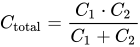
Supercapacitors may have either symmetric or asymmetric electrodes. Symmetry implies that both electrodes have the same capacitance value, yielding a total capacitance of half the value of each single electrode (if C1 = C2, then Ctotal = ½ C1). For asymmetric capacitors, the total capacitance can be taken as that of the electrode with the smaller capacitance (if C1 >> C2, then Ctotal ≈ C2).
Storage principles
[edit]Electrochemical capacitors use the double-layer effect to store electric energy; however, this double-layer has no conventional solid dielectric to separate the charges. There are two storage principles in the electric double-layer of the electrodes that contribute to the total capacitance of an electrochemical capacitor:[22]
- Double-layer capacitance, electrostatic storage of the electrical energy achieved by separation of charge in a Helmholtz double layer.[23]
- Pseudocapacitance, electrochemical storage of the electrical energy. The original type uses faradaic redox reactions with charge-transfer.[15]
Both capacitances are only separable by measurement techniques. The amount of charge stored per unit voltage in an electrochemical capacitor is primarily a function of the electrode size, although the amount of capacitance of each storage principle can vary extremely.
Electrical double-layer capacitance
[edit]
Every electrochemical capacitor has two electrodes, mechanically separated by a separator, which are ionically connected to each other via the electrolyte. The electrolyte is a mixture of positive and negative ions dissolved in a solvent such as water. At each of the two electrode surfaces originates an area in which the liquid electrolyte contacts the conductive metallic surface of the electrode. This interface forms a common boundary among two different phases of matter, such as an insoluble solid electrode surface and an adjacent liquid electrolyte. In this interface occurs a very special phenomenon of the double layer effect.[24]
Applying a voltage to an electrochemical capacitor causes both electrodes in the capacitor to generate electrical double-layers. These double-layers consist of two layers of charges: one electronic layer is in the surface lattice structure of the electrode, and the other, with opposite polarity, emerges from dissolved and solvated ions in the electrolyte. The two layers are separated by a monolayer of solvent molecules, e.g., for water as solvent by water molecules, called inner Helmholtz plane (IHP). Solvent molecules adhere by physical adsorption on the surface of the electrode and separate the oppositely polarized ions from each other, and can be idealised as a molecular dielectric. In the process, there is no transfer of charge between electrode and electrolyte, so the forces that cause the adhesion are not chemical bonds, but physical forces, e.g., electrostatic forces. The adsorbed molecules are polarized, but, due to the lack of transfer of charge between electrolyte and electrode, suffered no chemical changes.
The amount of charge in the electrode is matched by the magnitude of counter-charges in outer Helmholtz plane (OHP). This double-layer phenomena stores electrical charges as in a conventional capacitor. The double-layer charge forms a static electric field in the molecular layer of the solvent molecules in the IHP that corresponds to the strength of the applied voltage.

The double-layer serves approximately as the dielectric layer in a conventional capacitor, albeit with the thickness of a single molecule. Thus, the standard formula for conventional plate capacitors can be used to calculate their capacitance:[25]
- .

Accordingly, capacitance C is greatest in capacitors made from materials with a high permittivity ε, large electrode plate surface areas A and small distance between plates d. As a result, double-layer capacitors have much higher capacitance values than conventional capacitors, arising from the extremely large surface area of activated carbon electrodes and the extremely thin double-layer distance on the order of a few ångströms (0.3–0.8 nm), of order of the Debye length.[15][23]
Assuming that the minimum distance between the electrode and the charge accumulating region cannot be less than the typical distance between negative and positive charges in atoms of ~0.05 nm a general capacitance upper limit of ~18 μF/cm2 has been predicted for non-faradaic capacitors.[26]
The main drawback of carbon electrodes of double-layer SCs is small values of quantum capacitance[citation needed] which act in series[27] with capacitance of ionic space charge. Therefore, further increase of density of capacitance in SCs can be connected with increasing of quantum capacitance of carbon electrode nanostructures.[citation needed]
The amount of charge stored per unit voltage in an electrochemical capacitor is primarily a function of the electrode size. The electrostatic storage of energy in the double-layers is linear with respect to the stored charge, and correspond to the concentration of the adsorbed ions. Also, while charge in conventional capacitors is transferred via electrons, capacitance in double-layer capacitors is related to the limited moving speed of ions in the electrolyte and the resistive porous structure of the electrodes. Since no chemical changes take place within the electrode or electrolyte, charging and discharging electric double-layers in principle is unlimited. Real supercapacitors lifetimes are only limited by electrolyte evaporation effects.
Electrochemical pseudocapacitance
[edit]
Applying a voltage at the electrochemical capacitor terminals moves electrolyte ions to the opposite polarized electrode and forms a double-layer in which a single layer of solvent molecules acts as separator. Pseudocapacitance can originate when specifically adsorbed ions out of the electrolyte pervade the double-layer. This pseudocapacitance stores electrical energy by means of reversible faradaic redox reactions on the surface of suitable electrodes in an electrochemical capacitor with an electric double-layer.[11][22][23][28][29] Pseudocapacitance is accompanied with an electron charge-transfer between electrolyte and electrode coming from a de-solvated and adsorbed ion whereby only one electron per charge unit is participating. This faradaic charge transfer originates by a very fast sequence of reversible redox, intercalation or electrosorption processes. The adsorbed ion has no chemical reaction with the atoms of the electrode (no chemical bonds arise[30]) since only a charge-transfer take place.

The electrons involved in the faradaic processes are transferred to or from valence electron states (orbitals) of the redox electrode reagent. They enter the negative electrode and flow through the external circuit to the positive electrode where a second double-layer with an equal number of anions has formed. The electrons reaching the positive electrode are not transferred to the anions forming the double-layer, instead they remain in the strongly ionized and "electron hungry" transition-metal ions of the electrode's surface. As such, the storage capacity of faradaic pseudocapacitance is limited by the finite quantity of reagent in the available surface.
A faradaic pseudocapacitance only occurs together with a static double-layer capacitance, and its magnitude may exceed the value of double-layer capacitance for the same surface area by factor of 100, depending on the nature and the structure of the electrode, because all the pseudocapacitance reactions take place only with de-solvated ions, which are much smaller than solvated ion with their solvating shell.[11][28] The amount of pseudocapacitance has a linear function within narrow limits determined by the potential-dependent degree of surface coverage of the adsorbed anions.
The ability of electrodes to accomplish pseudocapacitance effects by redox reactions, intercalation or electrosorption strongly depends on the chemical affinity of electrode materials to the ions adsorbed on the electrode surface as well as on the structure and dimension of the electrode pores. Materials exhibiting redox behavior for use as electrodes in pseudocapacitors are transition-metal oxides like RuO2, IrO2, or MnO2 inserted by doping in the conductive electrode material such as active carbon, as well as conducting polymers such as polyaniline or derivatives of polythiophene covering the electrode material.
The amount of electric charge stored in a pseudocapacitance is linearly proportional to the applied voltage. The unit of pseudocapacitance is farad, same as that of capacitance.
Although conventional battery-type electrode materials also use chemical reactions to store charge, they show very different electrical profiles, as the rate of discharge is limited by the speed of diffusion. Grinding those materials down to nanoscale frees them of the diffusion limit and give them a more pseudocapacitative behavior, making them extrinsic pseudocapacitors. Chodankar et al. 2020, figure 2 shows the representative voltage-capacity curves for bulk LiCoO2, nano LiCoO2, a redox pseudocapacitor (RuO2), and a intercalation pseudocapacitor (T-Nb2O5).[31]: 5
Asymmetric capacitors
[edit]Supercapacitors can also be made with different materials and principles at the electrodes. If both of those materials use a fast, supercapacitor-type reaction (capacitance or pseudocapacitance), the result is called an asymmetric capacitor. The two electrodes have different electric potentials; when combined with proper balancing, the result is improved energy density with no loss of lifespan or current capacity.[31]: 8
Hybrid capacitors
[edit]A number of newer supercapacitors are "hybrid": only one electrode uses a fast reaction (capacitance or pseudocapacitance), the other using a more "battery-like" (slower but higher-capacity) material. Hybrid capacitors combine the rapid charge/discharge kinetics of electric double-layer capacitors (EDLCs) with the high energy density of pseudocapacitive or battery-type electrodes. These systems bridge the gap between conventional capacitors and batteries, making them critical for applications requiring both power and energy density.[32] For example, an EDLC anode can be combined with an activated carbon–Ni(OH)2 cathode, the latter being a slow faradaic material. The CV and GCD profiles of a hybrid capacitor have a shape between that of a battery and an SC, more similar to that of an SC. Hybrid capacitors have much higher energy density, but have inferior cycle life and current capacity owing to the slower electrode.[31]: 7
Potential distribution
[edit]


Conventional capacitors (also known as electrostatic capacitors), such as ceramic capacitors and film capacitors, consist of two electrodes separated by a dielectric material. When charged, the energy is stored in a static electric field that permeates the dielectric between the electrodes. The total energy increases with the amount of stored charge, which in turn correlates linearly with the potential (voltage) between the plates. The maximum potential difference between the plates (the maximal voltage) is limited by the dielectric's breakdown field strength. The same static storage also applies for electrolytic capacitors in which most of the potential decreases over the anode's thin oxide layer. The somewhat resistive liquid electrolyte (cathode) accounts for a small decrease of potential for "wet" electrolytic capacitors, while electrolytic capacitors with solid conductive polymer electrolyte this voltage drop is negligible.
In contrast, electrochemical capacitors (supercapacitors) consists of two electrodes separated by an ion-permeable membrane (separator) and electrically connected via an electrolyte. Energy storage occurs within the double-layers of both electrodes as a mixture of a double-layer capacitance and pseudocapacitance. When both electrodes have approximately the same resistance (internal resistance), the potential of the capacitor decreases symmetrically over both double-layers, whereby a voltage drop across the equivalent series resistance (ESR) of the electrolyte is achieved. For asymmetrical supercapacitors like hybrid capacitors the voltage drop between the electrodes could be asymmetrical. The maximum potential across the capacitor (the maximal voltage) is limited by the electrolyte decomposition voltage.
Both electrostatic and electrochemical energy storage in supercapacitors are linear with respect to the stored charge, just as in conventional capacitors. The voltage between the capacitor terminals is linear with respect to the amount of stored energy. Such linear voltage gradient differs from rechargeable electrochemical batteries, in which the voltage between the terminals remains independent of the amount of stored energy, providing a relatively constant voltage.
Comparison with other storage technologies
[edit]Supercapacitors compete with electrolytic capacitors and rechargeable batteries, especially lithium-ion batteries. The following table compares the major parameters of the three main supercapacitor families with electrolytic capacitors and batteries.
| Parameter | Aluminum electrolytic capacitors |
Supercapacitors | Lithium-ion batteries | |||
|---|---|---|---|---|---|---|
| Double-layer capacitors (memory backup) |
Pseudocapacitors | Hybrid (Li-ion)[33][34][35][36] | NTGS EDLC[37] (experimental) | |||
| Temperature range, degrees Celsius (°C) |
−40 – +125 °C | −40 – +70 °C | −20 – +70 °C | −20 – +65 °C | −20 – +60 °C | |
| Maximum voltage (V) | 4 – 630 V | 1.2 – 3.3 V | 2.2 – 3.3 V | 3.8 – 4.0 V | ~ 4.0 V | 4.2 V |
| Minimum voltage (V) | 0 V | 0 V | 2.5 V | 2.5 V | ||
| Recharge cycles, thousands (k) |
< unlimited | 100 k – 1 000 k | 100 k – 1 000 k | 10 k – 500 k | > 20 k | 0.5 k – 10 k |
| Capacitance, farads (F) |
≤ 2.7 F | 0.1 – 470 F | 100 – 12 000 F | 3 – 3 300 F | — | |
| Specific energy, watt-hours per kilogram (Wh/kg) |
0.01 – 0.3 Wh/kg |
1.5 – 3.9 Wh/kg |
4 – 9 Wh/kg |
37 Wh/kg | 206 Wh/kg | 100 – 265 Wh/kg |
| Specific power, watts per gram (W/g) |
> 100 W/g | 2 – 10 W/g | 3 – 10 W/g | 3 – 14 W/g | 32 W/g | 0.3 – 1.5 W/g |
| Self-discharge time at room temp. |
short (days) |
medium (weeks) |
medium (weeks) |
long (month) |
long (month) | |
| Efficiency (%) | 99% | 95% | 95% | 90% | 90% | |
| Working life at room temp., years (y) |
> 20 y | 5 – 10 y | 5 – 10 y | 5 – 10 y | 3 – 5 y | |
Electrolytic capacitors feature nearly unlimited charge/discharge cycles, high dielectric strength (up to 550 V) and good frequency response as alternating current (AC) reactance in the lower frequency range. Supercapacitors can store 10 to 100 times more energy than electrolytic capacitors, but they do not support AC applications.
With regards to rechargeable batteries, supercapacitors feature higher peak currents, low cost per cycle, no danger of overcharging, good reversibility, non-corrosive electrolyte and low material toxicity. Batteries offer lower purchase cost and stable voltage under discharge, but require complex electronic control and switching equipment, with consequent energy loss and spark hazard given a short.[clarification needed]
Styles
[edit]

.PNG)
1. terminals, 2. safety vent, 3. sealing disc, 4. aluminum can, 5. positive pole, 6. separator, 7. carbon electrode, 8. collector, 9. carbon electrode, 10. negative pole
.PNG)
1. positive electrode, 2. negative electrode, 3. separator
Supercapacitors are made in different styles, such as flat with a single pair of electrodes, wound in a cylindrical case, or stacked in a rectangular case. Because they cover a broad range of capacitance values, the size of the cases can vary.
Supercapacitors are constructed with two metal foils (current collectors), each coated with an electrode material such as activated carbon, which serve as the power connection between the electrode material and the external terminals of the capacitor. Specifically to the electrode material is a very large surface area. In this example the activated carbon is electrochemically etched, so that the surface area of the material is about 100,000 times greater than the smooth surface. The electrodes are kept apart by an ion-permeable membrane (separator) used as an insulator to protect the electrodes against short circuits. This construction is subsequently rolled or folded into a cylindrical or rectangular shape and can be stacked in an aluminum can or an adaptable rectangular housing. The cell is then impregnated with a liquid or viscous electrolyte of organic or aqueous type. The electrolyte, an ionic conductor, enters the pores of the electrodes and serves as the conductive connection between the electrodes across the separator. Finally, the housing is hermetically sealed to ensure stable behavior over the specified lifetime.
Types
[edit]
Electrical energy is stored in supercapacitors via two storage principles, static double-layer capacitance and electrochemical pseudocapacitance; and the distribution of the two types of capacitance depends on the material and structure of the electrodes. There are three types of supercapacitors based on storage principle:[15][23]
- Double-layer capacitors (EDLCs): with activated carbon electrodes or derivatives with much higher electrostatic double-layer capacitance than electrochemical pseudocapacitance
- Pseudocapacitors: with transition metal oxide or conducting polymer electrodes with a high electrochemical pseudocapacitance
- Hybrid capacitors: with asymmetric electrodes, one of which exhibits mostly electrostatic and the other mostly electrochemical capacitance, such as lithium-ion capacitors
Because double-layer capacitance and pseudocapacitance both contribute inseparably to the total capacitance value of an electrochemical capacitor, a correct description of these capacitors only can be given under the generic term. The concepts of supercapattery and supercabattery have been recently proposed to better represent those hybrid devices that behave more like the supercapacitor and the rechargeable battery, respectively.[38]
The capacitance value of a supercapacitor is determined by two storage principles:
- Double-layer capacitance – electrostatic storage of the electrical energy achieved by separation of charge in a Helmholtz double layer at the interface between the surface of a conductor electrode and an electrolytic solution electrolyte. The separation of charge distance in a double-layer is on the order of a few ångströms (0.3–0.8 nm) and is static in origin.[15]
- Pseudocapacitance – Electrochemical storage of the electrical energy, achieved by redox reactions, electrosorption or intercalation on the surface of the electrode by specifically adsorbed ions, that results in a reversible faradaic charge-transfer on the electrode.[15]
Double-layer capacitance and pseudocapacitance both contribute inseparably to the total capacitance value of a supercapacitor.[22] However, the ratio of the two can vary greatly, depending on the design of the electrodes and the composition of the electrolyte. Pseudocapacitance can increase the capacitance value by as much as a factor of ten over that of the double-layer by itself.[11][28]
Electric double-layer capacitors (EDLC) are electrochemical capacitors in which energy storage predominantly is achieved by double-layer capacitance. In the past, all electrochemical capacitors were called "double-layer capacitors". Contemporary usage sees double-layer capacitors, together with pseudocapacitors, as part of a larger family of electrochemical capacitors[11][28] called supercapacitors. They are also known as ultracapacitors.
Materials
[edit]The properties of supercapacitors come from the interaction of their internal materials. Especially, the combination of electrode material and type of electrolyte determine the functionality and thermal and electrical characteristics of the capacitors.
Electrodes
[edit]
Supercapacitor electrodes are generally thin coatings applied and electrically connected to a conductive, metallic current collector. Electrodes must have good conductivity, high temperature stability, long-term chemical stability (inertness), high corrosion resistance and high surface areas per unit volume and mass. Other requirements include environmental friendliness and low cost.
The amount of double-layer as well as pseudocapacitance stored per unit voltage in a supercapacitor is predominantly a function of the electrode surface area. Therefore, supercapacitor electrodes are typically made of porous, spongy material with an extraordinarily high specific surface area, such as activated carbon. Additionally, the ability of the electrode material to perform faradaic charge transfers enhances the total capacitance.
Generally the smaller the electrode's pores, the greater the capacitance and specific energy. However, smaller pores increase equivalent series resistance (ESR) and decrease specific power. Applications with high peak currents require larger pores and low internal losses, while applications requiring high specific energy need small pores.
Electrodes for EDLCs
[edit]The most commonly used electrode material for supercapacitors is carbon in various manifestations such as activated carbon (AC), carbon fibre-cloth (AFC), carbide-derived carbon (CDC),[39][40] carbon aerogel, graphite (graphene), graphane[41] and carbon nanotubes (CNTs).[22][42][43]
Carbon-based electrodes exhibit predominantly static double-layer capacitance, even though a small amount of pseudocapacitance may also be present depending on the pore size distribution. Pore sizes in carbons typically range from micropores (less than 2 nm) to mesopores (2-50 nm),[44] but only micropores (<2 nm) contribute to pseudocapacitance. As pore size approaches the solvation shell size, solvent molecules are excluded and only unsolvated ions fill the pores (even for large ions), increasing ionic packing density and storage capability by faradaic H
2 intercalation.[22]
Activated carbon
[edit]Activated carbon was the first material chosen for EDLC electrodes. Even though its electrical conductivity is approximately 0.003% that of metals (1,250 to 2,000 S/m), it is sufficient for supercapacitors.[23][15] Activated carbon is an extremely porous form of carbon with a high specific surface area — a common approximation is that 1 gram (0.035 oz) (a pencil-eraser-sized amount) has a surface area of roughly 1,000 to 3,000 square metres (11,000 to 32,000 sq ft)[42][44] — about the size of 4 to 12 tennis courts. The bulk form used in electrodes is low-density with many pores, giving high double-layer capacitance. Solid activated carbon, also termed consolidated amorphous carbon (CAC) is the most used electrode material for supercapacitors and may be cheaper than other carbon derivatives.[45] It is produced from activated carbon powder pressed into the desired shape, forming a block with a wide distribution of pore sizes. An electrode with a surface area of about 1000 m2/g results in a typical double-layer capacitance of about 10 μF/cm2 and a specific capacitance of 100 F/g. As of 2010[update] virtually all commercial supercapacitors use powdered activated carbon made from coconut shells.[46] Coconut shells produce activated carbon with more micropores than does charcoal made from wood.[44]
Activated carbon fibres
[edit]Activated carbon fibres (ACF) are produced from activated carbon and have a typical diameter of 10 μm. They can have micropores with a very narrow pore-size distribution that can be readily controlled. The surface area of ACF woven into a textile is about 2500 m2/g. Advantages of ACF electrodes include low electrical resistance along the fibre axis and good contact to the collector.[42] As for activated carbon, ACF electrodes exhibit predominantly double-layer capacitance with a small amount of pseudocapacitance due to their micropores.
Carbon aerogel
[edit]
Carbon aerogel is a highly porous, synthetic, ultralight material derived from an organic gel in which the liquid component of the gel has been replaced with a gas. Aerogel electrodes are made via pyrolysis of resorcinol-formaldehyde aerogels[47] and are more conductive than most activated carbons. They enable thin and mechanically stable electrodes with a thickness in the range of several hundred micrometres (μm) and with uniform pore size. Aerogel electrodes also provide mechanical and vibration stability for supercapacitors used in high-vibration environments. Researchers have created a carbon aerogel electrode with gravimetric densities of about 400–1200 m2/g and volumetric capacitance of 104 F/cm3, yielding a specific energy of 325 kJ/kg (90 Wh/kg) and specific power of 20 W/g.[48][49] Standard aerogel electrodes exhibit predominantly double-layer capacitance. Aerogel electrodes that incorporate composite material can add a high amount of pseudocapacitance.[50]
Carbide-derived carbon
[edit]
Carbide-derived carbon (CDC), also known as tunable nanoporous carbon, is a family of carbon materials derived from carbide precursors, such as binary silicon carbide and titanium carbide, that are transformed into pure carbon via physical, e.g., thermal decomposition or chemical, e.g., halogenation) processes.[51][52] Carbide-derived carbons can exhibit high surface area and tunable pore diameters (from micropores to mesopores) to maximize ion confinement, increasing pseudocapacitance by faradaic H
2 adsorption treatment. CDC electrodes with tailored pore design offer as much as 75% greater specific energy than conventional activated carbons. As of 2015[update], a CDC supercapacitor offered a specific energy of 10.1 Wh/kg, 3,500 F capacitance and over one million charge-discharge cycles.[53]
Graphene
[edit]
Graphene is a one-atom thick sheet of graphite, with atoms arranged in a regular hexagonal pattern,[54][55] also called "nanocomposite paper".[56]
Graphene has a theoretical specific surface area of 2630 m2/g which can theoretically lead to a capacitance of 550 F/g. In addition, an advantage of graphene over activated carbon is its higher electrical conductivity. As of 2012[update], a new development used graphene sheets directly as electrodes without collectors for portable applications.[57][58]
In one embodiment, a graphene-based supercapacitor uses curved graphene sheets that do not stack face-to-face, forming mesopores that are accessible to and wettable by ionic electrolytes at voltages up to 4 V. A specific energy of 85.6 Wh/kg (308 kJ/kg) is obtained at room temperature equaling that of a conventional nickel–metal hydride battery, but with 100–1000 times greater specific power.[59][60]
The two-dimensional structure of graphene improves charging and discharging. Charge carriers in vertically oriented sheets can quickly migrate into or out of the deeper structures of the electrode, thus increasing currents. Such capacitors may be suitable for 100/120 Hz filter applications, which are unreachable for supercapacitors using other carbon materials.[61]
Graphene Fabrication Techniques for Supercapacitors
[edit]Chemical vapor deposition is a popular fabrication method for graphene utilized in supercapacitors, producing a high quality monolayer or few-layer graphene. The process begins by introducing a Hydrocarbon (most commonly methane, CH4) into a reaction chamber. A metal catalyst such as copper (Cu) or nickel (Ni) are then placed in the reaction chamber to act as a substrate. These metals are frequently used due to their ability to decompose methane into free carbon atoms that will be used in the graphene formation. The chamber is then heated to temperatures between 700 and 1000 degrees Celsius in order to decompose the methane molecules at the surface of the substrate. The methane is decomposed into hydrogen gas (H2) that is vented from the chamber, and Carbon (C) atoms are released onto the substrate.[62]
As Carbon atoms are absorbed onto the substrate, they begin to diffuse along the surface and nucleate. The Carbon atoms will naturally arrange themselves in the honeycomb lattice of graphene. Depending on the temperature, pressure, and concentration of methane, the number of graphene layers produced will vary. Once the graphene layer is formed, the chamber is cooled down and the now coated substrate is removed. The graphene is then transferred from its metal substrate onto a new surface, depending on the application. The method to perform this transfer is typically a PMMA-mediated approach (poly methyl-methacrylate).[63] Graphene is especially valuable in Supercapacitors due to its low-resistance pathways for electron flow, which is an essential part of the high power output of supercapacitors.
Mechanical exfoliation is another fabrication method for graphene sheets used in supercapacitors. The process begins by selecting a high quality graphite, with high purity single-crystal graphite preferred. Next, select a piece of tape that can peel off thin layers of the graphite without taking off large chunks of the material, scotch tape is frequently used in this method. Repeatedly press the tape onto the graphite and gently peel it off. As the process is repeated, thinner and thinner graphene sheets will be transferred onto the tape.[64] Once a thin graphene layer has been pressed onto the tape, the tape is positioned on a clean substrate such as a silicon wafer or film. The tape with the graphene is pressed gently onto the substrate to transfer the graphene layers to the surface of the substrate and then slowly peeled off.
Carbon nanotubes
[edit]

Carbon nanotubes (CNTs), also called buckytubes, are carbon molecules with a cylindrical nanostructure. They have a hollow structure with walls formed by one-atom-thick sheets of graphite. These sheets are rolled at specific and discrete ("chiral") angles, and the combination of chiral angle and radius controls properties such as electrical conductivity, electrolyte wettability and ion access. Nanotubes are categorized as single-walled nanotubes (SWNTs) or multi-walled nanotubes (MWNTs). The latter have one or more outer tubes successively enveloping a SWNT, much like the Russian matryoshka dolls. SWNTs have diameters ranging between 1 and 3 nm. MWNTs have thicker coaxial walls, separated by spacing (0.34 nm) that is close to graphene's interlayer distance.
Nanotubes can grow vertically on the collector substrate, such as a silicon wafer. Typical lengths are 20 to 100 μm.[65]
Carbon nanotubes can greatly improve capacitor performance, due to the highly wettable surface area and high conductivity.[66][67]
A SWNT-based supercapacitor with aqueous electrolyte was systematically studied at University of Delaware in Prof. Bingqing Wei's group. Li et al., for the first time, discovered that the ion-size effect and the electrode-electrolyte wettability are the dominant factors affecting the electrochemical behavior of flexible SWCNTs-supercapacitors in different 1 molar aqueous electrolytes with different anions and cations. The experimental results also showed for flexible supercapacitor that it is suggested to put enough pressure between the two electrodes to improve the aqueous electrolyte CNT supercapacitor.[68]
CNTs can store about the same charge as activated carbon per unit surface area, but nanotubes' surface is arranged in a regular pattern, providing greater wettability. SWNTs have a high theoretical specific surface area of 1315 m2/g, while that for MWNTs is lower and is determined by the diameter of the tubes and degree of nesting, compared with a surface area of about 3000 m2/g of activated carbons. Nevertheless, CNTs have higher capacitance than activated carbon electrodes, e.g., 102 F/g for MWNTs and 180 F/g for SWNTs.[citation needed]
MWNTs have mesopores that allow for easy access of ions at the electrode–electrolyte interface. As the pore size approaches the size of the ion solvation shell, the solvent molecules are partially stripped, resulting in larger ionic packing density and increased faradaic storage capability. However, the considerable volume change during repeated intercalation and depletion decreases their mechanical stability. To this end, research to increase surface area, mechanical strength, electrical conductivity and chemical stability is ongoing.[66][69][70]
Electrodes for pseudocapacitors
[edit]MnO2 and RuO2 are typical materials used as electrodes for pseudocapacitors, since they have the electrochemical signature of a capacitive electrode (linear dependence on current versus voltage curve) as well as exhibiting aic behavior. Additionally, the charge storage originates from electron-transfer mechanisms rather than accumulation of ions in the electrochemical double layer. Pseudocapacitors were created through faradaic redox reactions that occur within the active electrode materials. More research was focused on transition-metal oxides such as MnO2 since transition-metal oxides have a lower cost compared to noble metal oxides such as RuO2. Moreover, the charge storage mechanisms of transition-metal oxides are based predominantly on pseudocapacitance. Two mechanisms of MnO2 charge storage behavior were introduced. The first mechanism implies the intercalation of protons (H+) or alkali metal cations (C+) in the bulk of the material upon reduction followed by deintercalation upon oxidation.[71]
- MnO2 + H+ (C+) + e− ⇌ MnOOH(C)[72]
The second mechanism is based on the surface adsorption of electrolyte cations on MnO2.
- (MnO2)surface + C+ + e− ⇌ (MnO2− C+)surface
Not every material that exhibits faradaic behavior can be used as an electrode for pseudocapacitors, such as Ni(OH)2 since it is a battery type electrode (non-linear dependence on current versus voltage curve).[73]
Metal oxides
[edit]Brian Evans Conway's research[11][12] described electrodes of transition metal oxides that exhibited high amounts of pseudocapacitance. Oxides of transition metals including ruthenium (RuO
2), iridium (IrO
2), iron (Fe
3O
4), manganese (MnO
2) or sulfides such as titanium sulfide (TiS
2) alone or in combination generate strong faradaic electron–transferring reactions combined with low resistance.[citation needed] Ruthenium dioxide in combination with H
2SO
4 electrolyte provides specific capacitance of 720 F/g and a high specific energy of 26.7 Wh/kg (96.12 kJ/kg).[74]
Charge/discharge takes place over a window of about 1.2 V per electrode. This pseudocapacitance of about 720 F/g is roughly 100 times higher than for double-layer capacitance using activated carbon electrodes. These transition metal electrodes offer excellent reversibility, with several hundred-thousand cycles. However, ruthenium is expensive and the 2.4 V voltage window for this capacitor limits their applications to military and space applications. Das et al. reported highest capacitance value (1715 F/g) for ruthenium oxide based supercapacitor with electrodeposited ruthenium oxide onto porous single wall carbon nanotube film electrode.[75] A high specific capacitance of 1715 F/g has been reported which closely approaches the predicted theoretical maximum RuO
2 capacitance of 2000 F/g.
In 2014, a RuO
2 supercapacitor anchored on a graphene foam electrode delivered specific capacitance of 502.78 F/g and areal capacitance of 1.11 F/cm2) leading to a specific energy of 39.28 Wh/kg and specific power of 128.01 kW/kg over 8,000 cycles with constant performance. The device was a three-dimensional (3D) sub-5 nm hydrous ruthenium-anchored graphene and carbon nanotube (CNT) hybrid foam (RGM) architecture. The graphene foam was conformally covered with hybrid networks of RuO
2 nanoparticles and anchored CNTs.[76][77]
Less expensive oxides of iron, vanadium, nickel and cobalt have been tested in aqueous electrolytes, but none has been investigated as much as manganese dioxide (MnO
2). However, none of these oxides are in commercial use.[78]
Conductive polymers
[edit]Another approach uses electron-conducting polymers as pseudocapacitive material. Although mechanically weak, conductive polymers have high conductivity, resulting in a low ESR[clarification needed] and a relatively high capacitance. Such conducting polymers include polyaniline, polythiophene, polypyrrole and polyacetylene. Such electrodes also employ electrochemical doping or dedoping of the polymers with anions and cations. Electrodes made from, or coated with, conductive polymers have costs comparable to carbon electrodes.
Conducting polymer electrodes generally suffer from limited cycling stability.[citation needed] However, polyacene electrodes provide up to 10,000 cycles, much better than batteries.[79]
Electrodes for hybrid capacitors
[edit]All commercial hybrid supercapacitors are asymmetric. They combine an electrode with high amount of pseudocapacitance with an electrode with a high amount of double-layer capacitance. In such systems the faradaic pseudocapacitance electrode with their higher capacitance provides high specific energy while the non-faradaic EDLC electrode enables high specific power. An advantage of the hybrid-type supercapacitors compared with symmetrical EDLC's is their higher specific capacitance value as well as their higher rated voltage and correspondingly their higher specific energy.[citation needed]
Advanced electrode materials
Nickel-cobalt oxides (NiCo2O4): NiCo2O4 spinel structures synthesized via hydrothermal methods exhibit a theoretical capacitance of ~3,500 F/g due to synergistic redox contributions from nickel (Ni2+/Ni3+) and cobalt (Co2+/Co3+) ions. Asymmetric configurations pairing NiCo2O4 cathodes with activated carbon anodes achieve energy densities of 89.6 Wh/kg at 796 W/kg, retaining 93% capacitance after 10,000 cycles.[80]
Graphene-metal oxide hybrids: Graphene-MnO2 nanocomposites leverage graphene's high electrical conductivity (106 S/m) and MnO2's pseudocapacitance. Atomic layer deposition (ALD) creates uniform MnO2 coatings on graphene nanosheets, achieving 1,100 F/g with 95% cycle stability over 5,000 cycles. These hybrids are scalable for grid storage applications.[80]
Iron-based composites: Core-shell Fe3O4@carbon structures combine double-layer capacitance (carbon shell) and Faradaic reactions (Fe3O4 core), delivering 32.2 Wh/kg energy density with 85% retention after 5,000 cycles. These low-cost materials mitigate reliance on critical minerals like cobalt.[80]
Structural composite supercapacitors: Carbon fiber electrodes coated with carbon nanotubes (CNTs) or graphene nanoplatelets serve dual roles as energy storage media and mechanical reinforcement. CNT-coated fibers achieve 120 F/g capacitance while maintaining tensile strengths >2 GPa, enabling 15–30% weight reductions in electric vehicle battery packs.[80]
Solid-state architectures
Gel polymer electrolytes: Flexible supercapacitors using polyvinyl alcohol (PVA)-H2SO4 gel electrolytes retain 98% capacitance after 5,000 bending cycles. These devices operate across a wide temperature range (−40 °C to 80 °C), making them suitable for wearable electronics.[81]
High-temperature designs: ALD-coated barium titanate (BaTiO3) ceramics sintered at 1,100 °C exhibit permittivity >8,000 and breakdown voltages exceeding 500 V, enabling ultracapacitors for aerospace energy systems.[81]
Performance comparison
| Hybrid type | Energy density (Wh/kg) | Power density (kW/kg) | Cycle life | Operating voltage |
|---|---|---|---|---|
| NiCo2O4 // Activated C | 89.6 | 0.796 | 10,000 | 1.6 V |
| Li-doped carbon hybrid | 14 | 10 | 50,000 | 3.8–4 V |
| Fe3O4@Carbon composite | 32.2 | 0.747 | 5,000 | 1.2 V |
Table: Comparative performance of hybrid supercapacitors.
Sustainability and policy
[edit]Closed-loop recycling recovers 92% of activated carbon from spent electrodes, reducing reliance on critical materials like cobalt. The U.S. Department of Energy's Critical Material Innovation Program funds research into graphene-carbon nanotube hybrids, aiming to reduce production costs by 40% by 2030.[82]
Composite electrodes
[edit]Composite electrodes for hybrid-type supercapacitors are constructed from carbon-based material with incorporated or deposited pseudocapacitive active materials like metal oxides and conducting polymers. As of 2013[update] most research for supercapacitors explores composite electrodes. CNTs give a backbone for a homogeneous distribution of metal oxide or electrically conducting polymers (ECPs), producing good pseudocapacitance and good double-layer capacitance. These electrodes achieve higher capacitances than either pure carbon or pure metal oxide or polymer-based electrodes. This is attributed to the accessibility of the nanotubes' tangled mat structure, which allows a uniform coating of pseudocapacitive materials and three-dimensional charge distribution. The process to anchor pseudocapactive materials usually uses a hydrothermal process. However, a recent researcher, Li et al., from the University of Delaware found a facile and scalable approach to precipitate MnO2 on a SWNT film to make an organic-electrolyte based supercapacitor.[83]
Another way to enhance CNT electrodes is by doping with a pseudocapacitive dopant as in lithium-ion capacitors. In this case the relatively small lithium atoms intercalate between the layers of carbon.[84] The anode is made of lithium-doped carbon, which enables lower negative potential with a cathode made of activated carbon. This results in a larger voltage of 3.8-4 V that prevents electrolyte oxidation. As of 2007 they had achieved capacitance of 550 F/g.[9] and reach a specific energy up to 14 Wh/kg (50.4 kJ/kg).[85]
Battery-type electrodes
[edit]Rechargeable battery electrodes influenced the development of electrodes for new hybrid-type supercapacitor electrodes as for lithium-ion capacitors.[86] Together with a carbon EDLC electrode in an asymmetric construction offers this configuration higher specific energy than typical supercapacitors with higher specific power, longer cycle life and faster charging and recharging times than batteries.
Asymmetric electrodes (pseudo/EDLC)
[edit]Recently some asymmetric hybrid supercapacitors were developed in which the positive electrode were based on a real pseudocapacitive metal oxide electrode (not a composite electrode), and the negative electrode on an EDLC activated carbon electrode.
Asymmetric supercapacitors (ASC) have shown a great potential candidate for high-performance supercapacitor due to their wide operating potential which can remarkably enhance the capacitive behavior. An advantage of this type of supercapacitors is their higher voltage and correspondingly their higher specific energy (up to 10-20 Wh/kg (36-72 kJ/kg)).[citation needed]And they also have good cycling stability.[87][88][89][90]
For example, researchers use a kind of novel skutterudite Ni–CoP3 nanosheets and use it as positive electrodes with activated carbon (AC) as negative electrodes to fabricate asymmetric supercapacitor (ASC). It exhibits high energy density of 89.6 Wh/kg at 796 W/kg and stability of 93% after 10,000 cycles, which can be a great potential to be an excellent next-generation electrode candidate.[90] Also, carbon nanofibers/poly(3,4-ethylenedioxythiophene)/manganese oxide (f-CNFs/PEDOT/MnO2) were used as positive electrodes and AC as negative electrodes. It has high specific energy of 49.4 Wh/kg and good cycling stability (81.06% after cycling 8000 times).[88] Besides, many kinds of nanocomposite are being studied as electrodes, like NiCo2S4@NiO,[89] MgCo2O4@MnO2 and so on. For example, Fe-SnO2@CeO2 nanocomposite used as electrode can provide a specific energy and specific power of 32.2 Wh/kg and 747 W/kg. The device exhibited the capacitance retention of 85.05% over 5000 cycles of operation.[87] As far as known no commercial offered supercapacitors with such kind of asymmetric electrodes are on the market.
Electrolytes
[edit]Electrolytes consist of a solvent and dissolved chemicals that dissociate into positive cations and negative anions, making the electrolyte electrically conductive. The more ions the electrolyte contains, the better its conductivity. In supercapacitors electrolytes are the electrically conductive connection between the two electrodes. Additionally, in supercapacitors the electrolyte provides the molecules for the separating monolayer in the Helmholtz double-layer and delivers the ions for pseudocapacitance.
The electrolyte determines the capacitor's characteristics: its operating voltage, temperature range, ESR and capacitance. With the same activated carbon electrode an aqueous electrolyte achieves capacitance values of 160 F/g, while an organic electrolyte achieves only 100 F/g.[91]
The electrolyte must be chemically inert and not chemically attack the other materials in the capacitor to ensure long time stable behavior of the capacitor's electrical parameters. The electrolyte's viscosity must be low enough to wet the porous, sponge-like structure of the electrodes. An ideal electrolyte does not exist, forcing a compromise between performance and other requirements.
Water is a relatively good solvent for inorganic chemicals. Treated with acids such as sulfuric acid (H
2SO
4), alkalis such as potassium hydroxide (KOH), or salts such as quaternary phosphonium salts, sodium perchlorate (NaClO
4), lithium perchlorate (LiClO
4) or lithium hexafluoride arsenate (LiAsF
6), water offers relatively high conductivity values of about 100 to 1000 mS/cm. Aqueous electrolytes have a dissociation voltage of 1.15 V per electrode (2.3 V capacitor voltage) and a relatively low operating temperature range. They are used in supercapacitors with low specific energy and high specific power.
Electrolytes with organic solvents such as acetonitrile, propylene carbonate, tetrahydrofuran, diethyl carbonate, γ-butyrolactone and solutions with quaternary ammonium salts or alkyl ammonium salts such as tetraethylammonium tetrafluoroborate (N(Et)
4BF
4[92]) or triethyl (metyl) tetrafluoroborate (NMe(Et)
3BF
4) are more expensive than aqueous electrolytes, but they have a higher dissociation voltage of typically 1.35 V per electrode (2.7 V capacitor voltage), and a higher temperature range. The lower electrical conductivity of organic solvents (10 to 60 mS/cm) leads to a lower specific power, but since the specific energy increases with the square of the voltage, a higher specific energy.
Ionic electrolytes consists of liquid salts that can be stable in a wider electrochemical window, enabling capacitor voltages above 3.5 V. Ionic electrolytes typically have an ionic conductivity of a few mS/cm, lower than aqueous or organic electrolytes.[93]
Separators
[edit]Separators have to physically separate the two electrodes to prevent a short circuit by direct contact. It can be very thin (a few hundredths of a millimeter) and must be very porous to the conducting ions to minimize ESR. Furthermore, separators must be chemically inert to protect the electrolyte's stability and conductivity. Inexpensive components use open capacitor papers. More sophisticated designs use nonwoven porous polymeric films like polyacrylonitrile or Kapton, woven glass fibers or porous woven ceramic fibres.[94][95]
Collectors and housing
[edit]Current collectors connect the electrodes to the capacitor's terminals. The collector is either sprayed onto the electrode or is a metal foil. They must be able to distribute peak currents of up to 100 A. If the housing is made of a metal (typically aluminum), the collectors should be made from the same material to avoid forming a corrosive galvanic cell.
Electrical parameters
[edit]Capacitance
[edit]


Capacitance values for commercial capacitors are specified as "rated capacitance CR". This is the value for which the capacitor has been designed. The value for an actual component must be within the limits given by the specified tolerance. Typical values are in the range of farads (F), three to six orders of magnitude larger than those of electrolytic capacitors. The capacitance value results from the energy (expressed in Joule) of a loaded capacitor loaded via a DC voltage VDC.

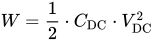
This value is also called the "DC capacitance".
Measurement
[edit]
Conventional capacitors are normally measured with a small AC voltage (0.5 V) and a frequency of 100 Hz or 1 kHz depending on the capacitor type. The AC capacitance measurement offers fast results, important for industrial production lines. The capacitance value of a supercapacitor depends strongly on the measurement frequency, which is related to the porous electrode structure and the limited electrolyte's ion mobility. Even at a low frequency of 10 Hz, the measured capacitance value drops from 100 to 20 percent of the DC capacitance value.
This extraordinarily strong frequency dependence can be explained by the different distances the ions have to move in the electrode's pores. The area at the beginning of the pores can be easily accessed by the ions; this short distance is accompanied by low electrical resistance. The greater the distance the ions have to cover, the higher the resistance. This phenomenon can be described with a series circuit of cascaded RC (resistor/capacitor) elements with serial RC time constants. These result in delayed current flow, reducing the total electrode surface area that can be covered with ions if polarity changes – capacitance decreases with increasing AC frequency. Thus, the total capacitance is achieved only after longer measuring times. Out of the reason of the very strong frequency dependence of the capacitance, this electrical parameter has to be measured with a special constant current charge and discharge measurement, defined in IEC standards 62391-1 and -2.
Measurement starts with charging the capacitor. The voltage has to be applied and after the constant current/constant voltage power supply has achieved the rated voltage, the capacitor must be charged for 30 minutes. Next, the capacitor has to be discharged with a constant discharge current Idischarge. Then the time t1 and t2, for the voltage to drop from 80% (V1) to 40% (V2) of the rated voltage is measured. The capacitance value is calculated as:

The value of the discharge current is determined by the application. The IEC standard defines four classes:
- Memory backup, discharge current in mA = 1 • C (F)
- Energy storage, discharge current in mA = 0,4 • C (F) • V (V)
- Power, discharge current in mA = 4 • C (F) • V (V)
- Instantaneous power, discharge current in mA = 40 • C (F) • V (V)
The measurement methods employed by individual manufacturers are mainly comparable to the standardized methods.[96][97]
The standardized measuring method is too time consuming for manufacturers to use during production for each individual component. For industrial-produced capacitors, the capacitance value is instead measured with a faster, low-frequency AC voltage, and a correlation factor is used to compute the rated capacitance.
This frequency dependence affects capacitor operation. Rapid charge and discharge cycles mean that neither the rated capacitance value nor specific energy are available. In this case the rated capacitance value is recalculated for each application condition.
The time t a supercapacitor can deliver a constant current I can be calculated as:
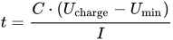
as the capacitor voltage decreases from Ucharge down to Umin.
If the application needs a constant power P for a certain time t this can be calculated as:

wherein also the capacitor voltage decreases from Ucharge down to Umin.
Operating voltage
[edit]

Supercapacitors are low voltage components. Safe operation requires that the voltage remain within specified limits. The rated voltage UR is the maximum DC voltage or peak pulse voltage that may be applied continuously and remain within the specified temperature range. Capacitors should never be subjected to voltages continuously in excess of the rated voltage.
The rated voltage includes a safety margin against the electrolyte's breakdown voltage at which the electrolyte decomposes. The breakdown voltage decomposes the separating solvent molecules in the Helmholtz double-layer, e.g. water splits into hydrogen and oxygen. The solvent molecules then cannot separate the electrical charges from each other. Higher voltages than rated voltage cause hydrogen gas formation or a short circuit.
Standard supercapacitors with aqueous electrolyte normally are specified with a rated voltage of 2.1 to 2.3 V and capacitors with organic solvents with 2.5 to 2.7 V. Lithium-ion capacitors with doped electrodes may reach a rated voltage of 3.8 to 4 V, but have a low voltage limit of about 2.2 V. Supercapacitors with ionic electrolytes can exceed an operating voltage of 3.5 V.[93]
Operating supercapacitors below the rated voltage improves the long-time behavior of the electrical parameters. Capacitance values and internal resistance during cycling are more stable and lifetime and charge/discharge cycles may be extended.[97]
Higher application voltages require connecting cells in series. Since each component has a slight difference in capacitance value and ESR, it is necessary to actively or passively balance them to stabilize the applied voltage. Passive balancing employs resistors in parallel with the supercapacitors. Active balancing may include electronic voltage management above a threshold that varies the current.
Internal resistance
[edit]
Charging/discharging a supercapacitor is connected to the movement of charge carriers (ions) in the electrolyte across the separator to the electrodes and into their porous structure. Losses occur during this movement that can be measured as the internal DC resistance.
With the electrical model of cascaded, series-connected RC (resistor/capacitor) elements in the electrode pores, the internal resistance increases with the increasing penetration depth of the charge carriers into the pores. The internal DC resistance is time dependent and increases during charge/discharge. In applications often only the switch-on and switch-off range is interesting. The internal resistance Ri can be calculated from the voltage drop ΔV2 at the time of discharge, starting with a constant discharge current Idischarge. It is obtained from the intersection of the auxiliary line extended from the straight part and the time base at the time of discharge start (see picture right). Resistance can be calculated by:
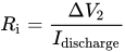
The discharge current Idischarge for the measurement of internal resistance can be taken from the classification according to IEC 62391-1.
This internal DC resistance Ri should not be confused with the internal AC resistance called equivalent series resistance (ESR) normally specified for capacitors. It is measured at 1 kHz. ESR is much smaller than DC resistance. ESR is not relevant for calculating supercapacitor inrush currents or other peak currents.
Ri determines several supercapacitor properties. It limits the charge and discharge peak currents as well as charge/discharge times. Ri and the capacitance C results in the time constant


This time constant determines the charge/discharge time. A 100 F capacitor with an internal resistance of 30 mΩ for example, has a time constant of 0.03 • 100 = 3 s. After 3 seconds charging with a current limited only by internal resistance, the capacitor has 63.2% of full charge (or is discharged to 36.8% of full charge).
Standard capacitors with constant internal resistance fully charge during about 5 τ. Since internal resistance increases with charge/discharge, actual times cannot be calculated with this formula. Thus, charge/discharge time depends on specific individual construction details.
Current load and cycle stability
[edit]Because supercapacitors operate without forming chemical bonds, current loads, including charge, discharge and peak currents are not limited by reaction constraints. Current load and cycle stability can be much higher than for rechargeable batteries. Current loads are limited only by internal resistance, which may be substantially lower than for batteries.
Internal resistance "Ri" and charge/discharge currents or peak currents "I" generate internal heat losses "Ploss" according to:
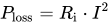
This heat must be released and distributed to the ambient environment to maintain operating temperatures below the specified maximum temperature.
Heat generally defines capacitor lifetime due to electrolyte diffusion. The heat generation coming from current loads should be smaller than 5 to 10 K at maximum ambient temperature (which has only minor influence on expected lifetime). For that reason the specified charge and discharge currents for frequent cycling are determined by internal resistance.
The specified cycle parameters under maximal conditions include charge and discharge current, pulse duration and frequency. They are specified for a defined temperature range and over the full voltage range for a defined lifetime. They can differ enormously depending on the combination of electrode porosity, pore size and electrolyte. Generally a lower current load increases capacitor life and increases the number of cycles. This can be achieved either by a lower voltage range or slower charging and discharging.[97]
Supercapacitors (except those with polymer electrodes) can potentially support more than one million charge/discharge cycles without substantial capacity drops or internal resistance increases. Beneath the higher current load is this the second great advantage of supercapacitors over batteries. The stability results from the dual electrostatic and electrochemical storage principles.
The specified charge and discharge currents can be significantly exceeded by lowering the frequency or by single pulses. Heat generated by a single pulse may be spread over the time until the next pulse occurs to ensure a relatively small average heat increase. Such a "peak power current" for power applications for supercapacitors of more than 1000 F can provide a maximum peak current of about 1000 A.[98] Such high currents generate high thermal stress and high electromagnetic forces that can damage the electrode-collector connection requiring robust design and construction of the capacitors.
Device capacitance and resistance dependence on operating voltage and temperature
[edit]
Device parameters such as capacitance initial resistance and steady state resistance are not constant, but are variable and dependent on the device's operating voltage. Device capacitance will have a measurable increase as the operating voltage increases. For example: a 100F device can be seen to vary 26% from its maximum capacitance over its entire operational voltage range. Similar dependence on operating voltage is seen in steady state resistance (Rss) and initial resistance (Ri).[99] Device properties can also be seen to be dependent on device temperature. As the temperature of the device changes either through operation of varying ambient temperature, the internal properties such as capacitance and resistance will vary as well. Device capacitance is seen to increase as the operating temperature increases.[99]
Energy capacity
[edit]
Supercapacitors occupy the gap between high power/low energy electrolytic capacitors and low power/high energy rechargeable batteries. The energy Wmax (expressed in Joule) that can be stored in a capacitor is given by the formula
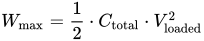
This formula describes the amount of energy stored and is often used to describe new research successes. However, only part of the stored energy is available to applications, because the voltage drop and the time constant over the internal resistance mean that some of the stored charge is inaccessible. The effective realized amount of energy Weff is reduced by the used voltage difference between Vmax and Vmin and can be represented as:[citation needed]

This formula also represents the energy asymmetric voltage components such as lithium ion capacitors.
Specific energy and specific power
[edit]The amount of energy that can be stored in a capacitor per mass of that capacitor is called its specific energy. Specific energy is measured gravimetrically (per unit of mass) in watt-hours per kilogram (Wh/kg).
The amount of energy can be stored in a capacitor per volume of that capacitor is called its energy density (also called volumetric specific energy in some literature). Energy density is measured volumetrically (per unit of volume) in watt-hours per litre (Wh/L). Units of liters and dm3 can be used interchangeably.
As of 2013[update] commercial energy density varies widely, but in general range from around 5 to 8 Wh/L. In comparison, petrol fuel has an energy density of 32.4 MJ/L or 9000 Wh/L.[100] Commercial specific energies range from around 0.5 to 15 Wh/kg. For comparison, an aluminum electrolytic capacitor stores typically 0.01 to 0.3 Wh/kg, while a conventional lead–acid battery stores typically 30 to 40 Wh/kg and modern lithium-ion batteries 100 to 265 Wh/kg. Supercapacitors can therefore store 10 to 100 times more energy than electrolytic capacitors, but only one tenth as much as batteries.[citation needed] For reference, petrol fuel has a specific energy of 44.4 MJ/kg or 12300 Wh/kg.
Although the specific energy of supercapacitors is defavorably compared with batteries, capacitors have the important advantage of the specific power. Specific power describes the speed at which energy can be delivered to the load (or, in charging the device, absorbed from the generator). The maximum power Pmax specifies the power of a theoretical rectangular single maximum current peak of a given voltage. In real circuits the current peak is not rectangular and the voltage is smaller, caused by the voltage drop, so IEC 62391–2 established a more realistic effective power Peff for supercapacitors for power applications, which is half the maximum and given by the following formulas :
- ,
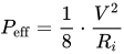
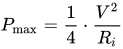
with V = voltage applied and Ri, the internal DC resistance of the capacitor.
Just like specific energy, specific power is measured either gravimetrically in kilowatts per kilogram (kW/kg, specific power) or volumetrically in kilowatts per litre (kW/L, power density). Supercapacitor specific power is typically 10 to 100 times greater than for batteries and can reach values up to 15 kW/kg.
Ragone charts relate energy to power and are a valuable tool for characterizing and visualizing energy storage components. With such a diagram, the position of specific power and specific energy of different storage technologies is easily to compare, see diagram.[101][102]
Lifetime
[edit]
Since supercapacitors do not rely on chemical changes in the electrodes (except for those with polymer electrodes), lifetimes depend mostly on the rate of evaporation of the liquid electrolyte. This evaporation is generally a function of temperature, current load, current cycle frequency and voltage. Current load and cycle frequency generate internal heat, so that the evaporation-determining temperature is the sum of ambient and internal heat. This temperature is measurable as core temperature in the center of a capacitor body. The higher the core temperature, the faster the evaporation, and the shorter the lifetime.
Evaporation generally results in decreasing capacitance and increasing internal resistance. According to IEC/EN 62391-2, capacitance reductions of over 30%, or internal resistance exceeding four times its data sheet specifications, are considered "wear-out failures", implying that the component has reached end-of-life. The capacitors are operable, but with reduced capabilities. Whether the aberration of the parameters have any influence on the proper functionality depends on the application of the capacitors.
Such large changes of electrical parameters specified in IEC/EN 62391-2 are usually unacceptable for high current load applications. Components that support high current loads use much smaller limits, e.g., 20% loss of capacitance or double the internal resistance.[103] The narrower definition is important for such applications, since heat increases linearly with increasing internal resistance, and the maximum temperature should not be exceeded. Temperatures higher than specified can destroy the capacitor.
The real application lifetime of supercapacitors, also called "service life," "life expectancy", or "load life", can reach 10 to 15 years or more, at room temperature. Such long periods cannot be tested by manufacturers. Hence, they specify the expected capacitor lifetime at the maximum temperature and voltage conditions. The results are specified in datasheets using the notation "tested time (hours)/max. temperature (°C)," such as "5000 h/65 °C". With this value, and expressions derived from historical data, lifetimes can be estimated for lower temperature conditions.
Datasheet lifetime specification is tested by the manufactures using an accelerated aging test called an "endurance test", with maximum temperature and voltage over a specified time. For a "zero defect" product policy, no wear out or total failure may occur during this test.
The lifetime specification from datasheets can be used to estimate the expected lifetime for a given design. The "10-degrees-rule" used for electrolytic capacitors with non-solid electrolyte is used in those estimations, and can be used for supercapacitors. This rule employs the Arrhenius equation: a simple formula for the temperature dependence of reaction rates. For every 10 °C reduction in operating temperature, the estimated life doubles.
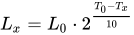
With:
- Lx = estimated lifetime
- L0 = specified lifetime
- T0 = upper specified capacitor temperature
- Tx = actual operating temperature of the capacitor cell
Calculated with this formula, capacitors specified with 5000 h at 65 °C, have an estimated lifetime of 20,000 h at 45 °C.
Lifetimes are also dependent on the operating voltage, because the development of gas in the liquid electrolyte depends on the voltage. The lower the voltage, the smaller the gas development, and the longer the lifetime. No general formula relates voltage to lifetime. The voltage dependent curves shown from the picture are an empirical result from one manufacturer.
Life expectancy for power applications may be also limited by current load or number of cycles. This limitation has to be specified by the relevant manufacturer and is strongly type dependent.
Self-discharge
[edit]Storing electrical energy in the double-layer separates the charge carriers within the pores by distances in the range of molecules. Irregularities can occur over this short distance, leading to a small exchange of charge carriers and gradual discharge. This self-discharge is called leakage current. Leakage depends on capacitance, voltage, temperature, and the chemical stability of the electrode/electrolyte combination. At room temperature, leakage is so low that it is specified as time to self-discharge in hours, days, or weeks. As an example, a 5.5 V/F Panasonic "Goldcapacitor" specifies a voltage drop at 20 °C from 5.5 V to 3 V in 600 hours (25 days or 3.6 weeks) for a double cell capacitor.[104]
Post charge voltage relaxation
[edit]
It has been noticed that after the EDLC experiences a charge or discharge, the voltage will drift over time, relaxing toward its previous voltage level. The observed relaxation can occur over several hours and is likely due to long diffusion time constants of the porous electrodes within the EDLC.[99]
Polarity
[edit]Since the positive and negative electrodes (or simply positrode and negatrode, respectively) of symmetric supercapacitors consist of the same material, theoretically supercapacitors have no true polarity and catastrophic failure does not normally occur. However reverse-charging a supercapacitor lowers its capacity, so it is recommended practice to maintain the polarity resulting from the formation of the electrodes during production. Asymmetric supercapacitors are inherently polar.
Pseudocapacitor and hybrid supercapacitors which have electrochemical charge properties may not be operated with reverse polarity, precluding their use in AC operation. However, this limitation does not apply to EDLC supercapacitors
A bar in the insulating sleeve identifies the negative terminal in a polarized component.
In some literature, the terms "anode" and "cathode" are used in place of negative electrode and positive electrode. Using anode and cathode to describe the electrodes in supercapacitors (and also rechargeable batteries, including lithium-ion batteries) can lead to confusion, because the polarity changes depending on whether a component is considered as a generator or as a consumer of current. In electrochemistry, cathode and anode are related to reduction and oxidation reactions, respectively. However, in supercapacitors based on electric double-layer capacitance, there is no oxidation nor reduction reactions on any of the two electrodes. Therefore, the concepts of cathode and anode do not apply.
Comparison of selected commercial supercapacitors
[edit]The range of electrodes and electrolytes available yields a variety of components suitable for diverse applications. The development of low-ohmic electrolyte systems, in combination with electrodes with high pseudocapacitance, enable many more technical solutions.
The following table shows differences among capacitors of various manufacturers in capacitance range, cell voltage, internal resistance (ESR, DC or AC value) and volumetric and gravimetric specific energy. In the table, ESR refers to the component with the largest capacitance value of the respective manufacturer. Roughly, they divide supercapacitors into two groups. The first group offers greater ESR values of about 20 milliohms and relatively small capacitance of 0.1 to 470 F. These are "double-layer capacitors" for memory back-up or similar applications. The second group offers 100 to 10,000 F with a significantly lower ESR value under 1 milliohm. These components are suitable for power applications. A correlation of some supercapacitor series of different manufacturers to the various construction features is provided in Pandolfo and Hollenkamp.[42]
In commercial double-layer capacitors, or, more specifically, EDLCs in which energy storage is predominantly achieved by double-layer capacitance, energy is stored by forming an electrical double layer of electrolyte ions on the surface of conductive electrodes. Since EDLCs are not limited by the electrochemical charge transfer kinetics of batteries, they can charge and discharge at a much higher rate, with lifetimes of more than 1 million cycles. The EDLC energy density is determined by operating voltage and the specific capacitance (farad/gram or farad/cm3) of the electrode/electrolyte system. The specific capacitance is related to the Specific Surface Area (SSA) accessible by the electrolyte, its interfacial double-layer capacitance, and the electrode material density.
Commercial EDLCs are based on two symmetric electrodes impregnated with electrolytes comprising tetraethylammonium tetrafluoroborate salts in organic solvents. Current EDLCs containing organic electrolytes operate at 2.7 V and reach energy densities around 5-8 Wh/kg and 7 to 10 Wh/L. The specific capacitance is related to the specific surface area (SSA) accessible by the electrolyte, its interfacial double-layer capacitance, and the electrode material density. Graphene-based platelets with mesoporous spacer material is a promising structure for increasing the SSA of the electrolyte.[105]
Standards
[edit]
Supercapacitors vary sufficiently that they are rarely interchangeable, especially those with higher specific energy. Applications range from low to high peak currents, requiring standardized test protocols.[106]
Test specifications and parameter requirements are specified in the generic specification IEC/EN 62391–1, Fixed electric double layer capacitors for use in electronic equipment.
The standard defines four application classes, according to discharge current levels:
- Memory backup
- Energy storage, mainly used for driving motors require a short time operation,
- Power, higher power demand for a long time operation,
- Instantaneous power, for applications that requires relatively high current units or peak currents ranging up to several hundreds of amperes even with a short operating time
Three further standards describe special applications:
- IEC 62391–2, Fixed electric double-layer capacitors for use in electronic equipment - Blank detail specification - Electric double-layer capacitors for power application
- IEC 62576, Electric double-layer capacitors for use in hybrid electric vehicles. Test methods for electrical characteristics
- BS/EN 61881-3, Railway applications. Rolling stock equipment. Capacitors for power electronics. Electric double-layer capacitors
Applications
[edit]Supercapacitors have advantages in applications where a large amount of power is needed for a relatively short time, where a very high number of charge/discharge cycles or a longer lifetime is required. Typical applications range from milliamp currents or milliwatts of power for up to a few minutes to several amps current or several hundred kilowatts power for much shorter periods.
Supercapacitors do not support alternating current (AC) applications.
Consumer electronics
[edit]In applications with fluctuating loads, such as laptop computers, PDAs, GPS, portable media players, hand-held devices,[107] and photovoltaic systems, supercapacitors can stabilize the power supply.
Supercapacitors deliver power for photographic flashes in digital cameras and for LED flashlights that can be charged in much shorter periods of time, e.g., 90 seconds.[108]
Some portable speakers are powered by supercapacitors.[109]
A cordless electric screwdriver with supercapacitors for energy storage has about half the run time of a comparable battery model, but can be fully charged in 90 seconds. It retains 85% of its charge after three months left idle.[110]
Power generation and distribution
[edit]Grid power buffering
[edit]Numerous non-linear loads, such as EV chargers, HEVs, air conditioning systems, and advanced power conversion systems cause current fluctuations and harmonics.[111][112] These current differences create unwanted voltage fluctuations and therefore power oscillations on the grid.[111] Power oscillations not only reduce the efficiency of the grid, but can cause voltage drops in the common coupling bus, and considerable frequency fluctuations throughout the entire system. To overcome this problem, supercapacitors can be implemented as an interface between the load and the grid to act as a buffer between the grid and the high pulse power drawn from the charging station.[113][114]
Low-power equipment power buffering
[edit]
Supercapacitors provide backup or emergency shutdown power to low-power equipment such as RAM, SRAM, micro-controllers and PC Cards. They are the sole power source for low energy applications such as automated meter reading (AMR)[115] equipment or for event notification in industrial electronics.
Supercapacitors buffer power to and from rechargeable batteries, mitigating the effects of short power interruptions and high current peaks. Batteries kick in only during extended interruptions, e.g., if the mains power or a fuel cell fails, which lengthens battery life.
Uninterruptible power supplies (UPS) may be powered by supercapacitors, which can replace much larger banks of electrolytic capacitors. This combination reduces the cost per cycle, saves on replacement and maintenance costs, enables the battery to be downsized and extends battery life.[116][117][118]
Supercapacitors provide backup power for actuators in wind turbine pitch systems, so that blade pitch can be adjusted even if the main supply fails.[119]
Voltage stabilization
[edit]Supercapacitors can stabilize voltage fluctuations for powerlines by acting as dampers. Wind and photovoltaic systems exhibit fluctuating supply evoked by gusting or clouds that supercapacitors can buffer within milliseconds.[120][121]
Micro grids
[edit]Micro grids are usually powered by clean and renewable energy. Most of this energy generation, however, is not constant throughout the day and does not usually match demand. Supercapacitors can be used for micro grid storage to instantaneously inject power when the demand is high and the production dips momentarily, and to store energy in the reverse conditions. They are useful in this scenario, because micro grids are increasingly producing power in DC, and capacitors can be utilized in both DC and AC applications. Supercapacitors work best in conjunction with chemical batteries. They provide an immediate voltage buffer to compensate for quick changing power loads due to their high charge and discharge rate through an active control system.[122] Once the voltage is buffered, it is put through an inverter to supply AC power to the grid. Supercapacitors cannot provide frequency correction in this form directly in the AC grid.[123][124]
Energy harvesting
[edit]Supercapacitors are suitable temporary energy storage devices for energy harvesting systems. In energy harvesting systems, the energy is collected from the ambient or renewable sources, e.g., mechanical movement, light or electromagnetic fields, and converted to electrical energy in an energy storage device. For example, it was demonstrated that energy collected from RF (radio frequency) fields (using an RF antenna as an appropriate rectifier circuit) can be stored to a printed supercapacitor. The harvested energy was then used to power an application-specific integrated circuit (ASIC) for over 10 hours.[125]
Batteries
[edit]The UltraBattery is a hybrid rechargeable lead-acid battery and a supercapacitor. Its cell construction contains a standard lead-acid battery positive electrode, standard sulphuric acid electrolyte and a specially prepared negative carbon-based electrode that store electrical energy with double-layer capacitance. The presence of the supercapacitor electrode alters the chemistry of the battery and affords it significant protection from sulfation in high rate partial state of charge use, which is the typical failure mode of valve regulated lead-acid cells used this way. The resulting cell performs with characteristics beyond either a lead-acid cell or a supercapacitor, with charge and discharge rates, cycle life, efficiency and performance all enhanced.
Medical
[edit]Supercapacitors are used in defibrillators where they can deliver 500 joules to shock the heart back into sinus rhythm.[126]
Military
[edit]Supercapacitors' low internal resistance supports applications that require short-term high currents. Among the earliest uses were motor startup (cold engine starts, particularly with diesels) for large engines in tanks and submarines. Supercapacitors buffer the battery, handling short current peaks, reducing cycling and extending battery life. Further military applications that require high specific power are phased array radar antennae, laser power supplies, military radio communications, avionics displays and instrumentation, backup power for airbag deployment and GPS-guided missiles and projectiles.
Transport
[edit]A primary challenge of all transport is reducing energy consumption and reducing CO
2 emissions. Recovery of braking energy (recuperation or regenerative braking) helps with both. This requires components that can quickly store and release energy over long times with a high cycle rate. Supercapacitors fulfill these requirements and are therefore used in various applications in transportation.
Aviation
[edit]In 2005, aerospace systems and controls company Diehl Luftfahrt Elektronik GmbH chose supercapacitors to power emergency actuators for doors and evacuation slides used in airliners, including the Airbus 380.[119]
Rail
[edit]
Supercapacitors can be used to supplement batteries in starter systems in diesel railroad locomotives with diesel–electric transmission. The capacitors capture the braking energy of a full stop and deliver the peak current for starting the diesel engine and acceleration of the train and ensures the stabilization of line voltage. Depending on the driving mode up to 30% energy saving is possible by recovery of braking energy. Low maintenance and environmentally friendly materials encouraged the choice of supercapacitors.[127]
Plant machinery
[edit]
Mobile hybrid Diesel–electric rubber tyred gantry cranes move and stack containers within a terminal. Lifting the boxes requires large amounts of energy. Some of the energy could be recaptured while lowering the load, resulting in improved efficiency.[128] A triple hybrid forklift truck uses fuel cells and batteries as primary energy storage and supercapacitors to buffer power peaks by storing braking energy. They provide the fork lift with peak power over 30 kW. The triple-hybrid system offers over 50% energy savings compared with Diesel or fuel-cell systems.[129] Supercapacitor-powered terminal tractors transport containers to warehouses. They provide an economical, quiet and pollution-free alternative to Diesel terminal tractors.[130]
Light rail
[edit]
Supercapacitors make it possible not only to reduce energy, but to replace overhead lines in historical city areas, so preserving the city's architectural heritage. This approach may allow many new light rail city lines to replace overhead wires that are too expensive to fully route.
In 2003 Mannheim adopted a prototype light-rail vehicle (LRV) using the MITRAC Energy Saver system from Bombardier Transportation to store mechanical braking energy with a roof-mounted supercapacitor unit.[131][132] It contains several units each made of 192 capacitors with 2700 F / 2.7 V interconnected in three parallel lines. This circuit results in a 518 V system with an energy content of 1.5 kWh. For acceleration when starting this "on-board-system" can provide the LRV with 600 kW and can drive the vehicle up to 1 km without overhead line supply, thus better integrating the LRV into the urban environment. Compared to conventional LRVs or Metro vehicles that return energy into the grid, onboard energy storage saves up to 30% and reduces peak grid demand by up to 50%.[133]

In 2009 supercapacitors enabled LRVs to operate in the historical city area of Heidelberg without overhead wires, thus preserving the city's architectural heritage.[citation needed] The SC equipment cost an additional €270,000 per vehicle, which was expected to be recovered over the first 15 years of operation. The supercapacitors are charged at stop-over stations when the vehicle is at a scheduled stop. In April 2011 German regional transport operator Rhein-Neckar, responsible for Heidelberg, ordered a further 11 units.[134]
In 2009, Alstom and RATP equipped a Citadis tram with an experimental energy recovery system called "STEEM".[135] The system is fitted with 48 roof-mounted supercapacitors to store braking energy, which provides tramways with a high level of energy autonomy by enabling them to run without overhead power lines on parts of its route, recharging while traveling on powered stop-over stations. During the tests, which took place between the Porte d'Italie and Porte de Choisy stops on line T3 of the tramway network in Paris, the tramset used an average of approximately 16% less energy.[136]

In 2012 tram operator Geneva Public Transport began tests of an LRV equipped with a prototype roof-mounted supercapacitor unit to recover braking energy.[137]
Siemens is delivering supercapacitor-enhanced light-rail transport systems that include mobile storage.[138]
Hong Kong's South Island metro line is to be equipped with two 2 MW energy storage units that are expected to reduce energy consumption by 10%.[139]
In August 2012 the CSR Zhuzhou Electric Locomotive corporation of China presented a prototype two-car light metro train equipped with a roof-mounted supercapacitor unit. The train can travel up 2 km without wires, recharging in 30 seconds at stations via a ground mounted pickup. The supplier claimed the trains could be used in 100 small and medium-sized Chinese cities.[140] Seven trams (street cars) powered by supercapacitors were scheduled to go into operation in 2014 in Guangzhou, China. The supercapacitors are recharged in 30 seconds by a device positioned between the rails. That powers the tram for up to 4 kilometres (2.5 mi).[141] As of 2017, Zhuzhou's supercapacitor vehicles are also used on the new Nanjing streetcar system, and are undergoing trials in Wuhan.[142]
In 2012, in Lyon (France), the SYTRAL (Lyon public transportation administration) started experiments of a "way side regeneration" system built by Adetel Group which has developed its own energy saver named "NeoGreen" for LRV, LRT and metros.[143]
In 2014 China began using trams powered with supercapacitors that are recharged in 30 seconds by a device positioned between the rails, storing power to run the tram for up to 4 km — more than enough to reach the next stop, where the cycle can be repeated.
In 2015, Alstom announced SRS, an energy storage system that charges supercapacitors on board a tram by means of ground-level conductor rails located at tram stops. This allows trams to operate without overhead lines for short distances.[144] The system has been touted as an alternative to the company's ground-level power supply (APS) system, or can be used in conjunction with it, as in the case of the VLT network in Rio de Janeiro, Brazil, which opened in 2016.[145]
CAF also offers supercapacitors on their Urbos 3 trams in the form of their ACR system.[146]
Buses
[edit]
Maxwell Technologies, an American supercapacitor maker, claimed that more than 20,000 hybrid buses use the devices to increase acceleration, particularly in China.[citation needed]
The first hybrid electric bus with supercapacitors in Europe came in 2001 in Nuremberg, Germany. It was MAN's so-called "Ultracapbus", and was tested in real operation in 2001/2002. The test vehicle was equipped with a diesel-electric drive in combination with supercapacitors. The system was supplied with 8 Ultracap modules of 80 V, each containing 36 components. The system worked with 640 V and could be charged/discharged at 400 A. Its energy content was 0.4 kWh with a weight of 400 kg.
The supercapacitors recaptured braking energy and delivered starting energy. Fuel consumption was reduced by 10 to 15% compared to conventional diesel vehicles. Other advantages included reduction of CO
2 emissions, quiet and emissions-free engine starts, lower vibration and reduced maintenance costs.[147][148]

As of 2002[update] in Luzern, Switzerland an electric bus fleet called TOHYCO-Rider was tested. The supercapacitors could be recharged via an inductive contactless high-speed power charger after every transportation cycle, within 3 to 4 minutes.[149]
In early 2005 Shanghai tested a new form of electric bus called capabus that runs without powerlines (catenary free operation) using large onboard supercapacitors that partially recharge whenever the bus is at a stop (under so-called electric umbrellas), and fully charge in the terminus. In 2006, two commercial bus routes began to use the capabuses; one of them is route 11 in Shanghai. It was estimated that the supercapacitor bus was cheaper than a lithium-ion battery bus, and one of its buses had one-tenth the energy cost of a diesel bus with lifetime fuel savings of $200,000.[150]
A hybrid electric bus called tribrid was unveiled in 2008 by the University of Glamorgan, Wales, for use as student transport. It is powered by hydrogen fuel or solar cells, batteries and ultracapacitors.[151][152]
Motor racing
[edit]

The FIA, a governing body for motor racing events, proposed in the Power-Train Regulation Framework for Formula 1 version 1.3 of 23 May 2007 that a new set of power train regulations be issued that includes a hybrid drive of up to 200 kW input and output power using "superbatteries" made with batteries and supercapacitors connected in parallel (KERS).[153][154] About 20% tank-to-wheel efficiency could be reached using the KERS system. The Toyota TS030 Hybrid LMP1 car, a racing car developed under Le Mans Prototype rules, uses a hybrid drivetrain with supercapacitors.[155][156] In the 2012 24 Hours of Le Mans race a TS030 qualified with a fastest lap only 1.055 seconds slower (3:24.842 versus 3:23.787)[157] than the fastest car, an Audi R18 e-tron quattro with flywheel energy storage. The supercapacitor and flywheel components, whose rapid charge-discharge capabilities help in both braking and acceleration, made the Audi and Toyota hybrids the fastest cars in the race. In the 2012 Le Mans race the two competing TS030s, one of which was in the lead for part of the race, both retired for reasons unrelated to the supercapacitors. The TS030 won three of the 8 races in the 2012 FIA World Endurance Championship season. In 2014 the Toyota TS040 Hybrid used a supercapacitor to add 480 horsepower from two electric motors.[141] In 2024 the IndyCar racing series introduced a hybrid power system composed of 20 supercapacitors.[158]
Hybrid electric vehicles
[edit]
Supercapacitor/battery combinations in electric vehicles (EV) and hybrid electric vehicles (HEV) are well investigated.[106][159][160] A 20 to 60% fuel reduction has been claimed by recovering brake energy in EVs or HEVs. The ability of supercapacitors to charge much faster than batteries, their stable electrical properties, broader temperature range and longer lifetime are suitable, but weight, volume and especially cost mitigate those advantages.
Supercapacitors' lower specific energy makes them unsuitable for use as a stand-alone energy source for long distance driving.[161] The fuel economy improvement between a capacitor and a battery solution is about 20% and is available only for shorter trips. For long distance driving the advantage decreases to 6%. Vehicles combining capacitors and batteries run only in experimental vehicles.[162]
As of 2013[update] all automotive manufacturers of EV or HEVs have developed prototypes that uses supercapacitors instead of batteries to store braking energy in order to improve driveline efficiency.[citation needed] The Mazda 6 was reportedly the first production car to use supercapacitors to recover braking energy. Branded as i-eloop, the system stores energy in a supercapacitor during deceleration and uses it to power on-board electrical systems while the engine is stopped by the stop-start system. The regenerative braking is claimed to reduce fuel consumption by about 10%.[163] The Toyota Yaris Hybrid-R concept car uses a supercapacitor to provide bursts of power. PSA Peugeot Citroën fit supercapacitors to some of its cars as part of its stop-start fuel-saving system, as this permits faster start-ups when the traffic lights turn green.[141] Russian Yo-cars Ё-mobile series was a concept and crossover hybrid vehicle working with a gasoline driven rotary vane type and an electric generator for driving the traction motors. A supercapacitor with relatively low capacitance recovers brake energy to power the electric motor when accelerating from a stop.[164]
Gondolas
[edit]
In Zell am See, Austria, an aerial lift connects the city with Schmittenhöhe mountain. The gondolas sometimes run 24 hours per day, using electricity for lights, door opening and communication. The only available time for recharging batteries at the stations is during the brief intervals of guest loading and unloading, which is too short to recharge batteries. Supercapacitors offer a fast charge, higher number of cycles and longer life time than batteries. Emirates Air Line (cable car), also known as the Thames cable car, is a 1-kilometre (0.62 mi) gondola line in London, UK, that crosses the Thames from the Greenwich Peninsula to the Royal Docks. The cabins are equipped with a modern infotainment system, which is powered by supercapacitors.[165][166]
Developments
[edit]As of 2013[update] commercially available lithium-ion supercapacitors offered the highest gravimetric specific energy to date, reaching 15 Wh/kg (54 kJ/kg). Research focuses on improving specific energy, reducing internal resistance, expanding temperature range, increasing lifetimes and reducing costs.[21] Projects include tailored-pore-size electrodes, pseudocapacitive coating or doping materials and improved electrolytes.
| Development | Date | Specific energy[A] | Specific power | Cycles | Capacitance | Notes |
|---|---|---|---|---|---|---|
| Graphene sheets compressed by capillary compression of a volatile liquid[167] | 2013 | 60 Wh/L | Subnanometer scale electrolyte integration created a continuous ion transport network. | |||
| Vertically aligned carbon nanotubes electrodes[9][67] | 2007 2009 2013 |
13.50 Wh/kg | 37.12 W/g | 300,000 | First realization[168] | |
| Curved graphene sheets[59][60] | 2010 | 85.6 Wh/kg | 550 F/g | Single-layers of curved graphene sheets that do not restack face-to-face, forming mesopores that are accessible to and wettable by environmentally friendly ionic electrolytes at a voltage up to 4 V. | ||
| KOH restructured graphite oxide[169][170] | 2011 | 85 Wh/kg | >10,000 | 200 F/g | Potassium hydroxide restructured the carbon to make a three dimensional porous network | |
| Activated graphene-based carbons as supercapacitor electrodes with macro- and mesopores[171] | 2013 | 74 Wh/kg | Three-dimensional pore structures in graphene-derived carbons in which mesopores are integrated into macroporous scaffolds with a surface area of 3290 m2/g | |||
| Conjugated microporous polymer[172][173] | 2011 | 53 Wh/kg | 10,000 | Aza-fused π-conjugated microporous framework | ||
| SWNT composite electrode[174] | 2011 | 990 W/kg | A tailored meso-macro pore structure held more electrolyte, ensuring facile ion transport | |||
| Nickel hydroxide nanoflake on CNT composite electrode[175] | 2012 | 50.6 Wh/kg | 3300 F/g | Asymmetric supercapacitor using the Ni(OH)2/CNT/NF electrode as the anode assembled with an activated carbon (AC) cathode achieving a cell voltage of 1.8 V | ||
| Battery-electrode nanohybrid[86] | 2012 | 40 Wh/L | 7.5 W/L | 10,000 | Li 4Ti 5O 12 (LTO) deposited on carbon nanofibres (CNF) anode and an activated carbon cathode | |
| Nickel cobaltite deposited on mesoporous carbon aerogel[176] | 2012 | 53 Wh/kg | 2.25 W/kg | 1700 F/g | Nickel cobaltite, a low cost and an environmentally friendly supercapacitive material | |
| Manganese dioxide intercalated nanoflakes[177] | 2013 | 110 Wh/kg | 1000 F/g | Wet electrochemical process intercalated Na(+) ions into MnO 2 interlayers. The nanoflake electrodes exhibit faster ionic diffusion with enhanced redox peaks. | ||
| 3D porous graphene electrode[178] | 2013 | 98 Wh/kg | 231 F/g | Wrinkled single layer graphene sheets a few nanometers in size, with at least some covalent bonds. | ||
| Graphene-based planar micro-supercapacitors for on-chip energy storage[179] | 2013 | 2.42 Wh/L | On chip line filtering | |||
| Nanosheet capacitors[180][181] | 2014 | 27.5 μF cm−2 | Electrodes: Ru0.95O20.2– Dielectric: Ca2Nb3O10–. Room-temperature solution-based manufacturing processes. Total thickness less than 30 nm. | |||
| LSG/manganese dioxide[182] | 2015 | 42 Wh/L | 10 kW/L | 10,000 | Three-dimensional laser-scribed graphene (LSG) structure for conductivity, porosity and surface area. Electrodes are around 15 microns thick. | |
| Laser-induced graphene/solid-state electrolyte[183][184] | 2015 | 0.02 mA/cm2 | 9 mF/cm2 | Survives repeated flexing. | ||
| Tungsten trioxide (WO3) nano-wires and two-dimensional enveloped by shells of a transition-metal dichalcogenide, tungsten disulfide (WS2)[185][186] | 2016 | ~100 Wh/L | 1 kW/L | 30,000 | 2D shells surrounding nanowires |
A Research into electrode materials requires measurement of individual components, such as an electrode or half-cell.[187] By using a counterelectrode that does not affect the measurements, the characteristics of only the electrode of interest can be revealed. Specific energy and power for real supercapacitors only have more or less roughly 1/3 of the electrode density.
Market
[edit]As of 2016[update] worldwide sales of supercapacitors is about US$400 million.[188]
The market for batteries (estimated by Frost & Sullivan) grew from US$47.5 billion, (76.4% or US$36.3 billion of which was rechargeable batteries) to US$95 billion.[189] The market for supercapacitors is still a small niche market that is not keeping pace with its larger rival.
In 2016, IDTechEx forecast sales to grow from $240 million to $2 billion by 2026, an annual increase of about 24%.[190]
Supercapacitor costs in 2006 were US$0.01 per farad or US$2.85 per kilojoule, moving in 2008 below US$0.01 per farad, and were expected to drop further in the medium term.[191]
See also
[edit]- Capa vehicle – Type of transportation vehicle
- Capacitor types – Manufacturing styles of an electronic device
- Conjugated microporous polymer – Type of porous material
- Electric vehicle battery – Rechargable battery used for vehicles
- Flywheel energy storage – Method of storing energy
- List of emerging technologies – New technologies actively in development
- Lithium-ion capacitor – Hybrid type of capacitor
- Mechanically powered flashlight – Human-powered flashlight
- Nanoflower – Compound that results in formations which in microscopic view resemble flowers
References
[edit]- ^ Häggström, Fredrik; Delsing, Jerker (27 November 2018). "IoT Energy Storage - A Forecast". Energy Harvesting and Systems. 5 (3–4): 43–51. doi:10.1515/ehs-2018-0010.
- ^ Bueno, Paulo R. (28 February 2019). "Nanoscale origins of super-capacitance phenomena". Journal of Power Sources. 414: 420–434. Bibcode:2019JPS...414..420B. doi:10.1016/j.jpowsour.2019.01.010. hdl:11449/190051.
- ^ Tehrani, Z.; Thomas, D.J.; Korochkina, T.; Phillips, C.O.; Lupo, D.; Lehtimäki, S.; O'Mahony, J.; Gethin, D.T. (2 January 2017). "Large-area printed supercapacitor technology for low-cost domestic green energy storage". Energy. 118: 1313–1321. Bibcode:2017Ene...118.1313T. doi:10.1016/j.energy.2016.11.019.
- ^ Linden's Handbook of Batteries, Fourth Edition. McGraw-Hill Education. 21 January 2024. ISBN 978-0-07-162421-3.
- ^ US 2800616, Becker, H.I., "Low voltage electrolytic capacitor", issued 23 July 1957
- ^ Ho, J.; Jow, T.R.; Boggs, S. (January 2010). "Historical introduction to capacitor technology". IEEE Electrical Insulation Magazine. 26 (1): 20–25. Bibcode:2010IEIM...26a..20H. doi:10.1109/mei.2010.5383924.
- ^ A brief history of supercapacitors AUTUMN 2007 Batteries & Energy Storage Technology Archived 6 January 2014 at the Wayback Machine
- ^ US 3288641, Rightmire, Robert A., "Electrical energy storage apparatus", issued 29 November 1966
- ^ a b c d e J. G. Schindall, The Change of the Ultra-Capacitors, IEEE Spectrum, November 2007 [1]
- ^ US 3536963, D. L. Boos, "Electrolytic capacitor having carbon paste electrodes", issued 27 October 1970
- ^ a b c d e f Conway, Brian Evans (1999), Electrochemical Supercapacitors: Scientific Fundamentals and Technological Applications (in German), Berlin, Germany: Springer, pp. 1–8, ISBN 978-0-306-45736-4
- ^ a b Conway, Brian Evans (May 1991). "Transition from 'Supercapacitor' to 'Battery' Behavior in Electrochemical Energy Storage". J. Electrochem. Soc. 138 (6): 1539–1548. Bibcode:1991JElS..138.1539C. doi:10.1149/1.2085829.
- ^ Panasonic, Electric Double Layer Capacitor, Technical guide,1. Introduction,Panasonic Goldcaps Archived 9 January 2014 at the Wayback Machine
- ^ "Electric double-layer capacitors". ELNA. Archived from the original on 13 March 2015. Retrieved 21 February 2015.
- ^ a b c d e f g Adam Marcus Namisnyk. A survey of electrochemical supercapacitor technology (PDF) (Technical report). Archived from the original (PDF) on 22 December 2014. Retrieved 21 February 2015.
- ^ US 5369547, David A. Evans, "Containers with anodes and cathodes with electrolytes", issued 29 November 1994
- ^ David A. Evans (Evans Company): High Energy Density Electrolytic-Electrochemical Hybrid Capacitor Archived 4 March 2016 at the Wayback Machine In: Proceedings of the 14th Capacitor & Resistor Technology Symposium. 22 March 1994
- ^ Evans Capacitor Company 2007 Capattery series Archived 15 June 2017 at the Wayback Machine
- ^ David A. Evans: The Littlest Big Capacitor - an Evans Hybrid Archived 3 March 2016 at the Wayback Machine Technical Paper, Evans Capacitor Company 2007
- ^ "FDK, Corporate Information, FDK History 2000s". FDK. Retrieved 21 February 2015.
- ^ a b Naoi, K.; Simon, P. (Spring 2008). "New Materials and New Configurations for Advanced Electrochemical Capacitors" (PDF). Interface. 17 (1): 34–37.
- ^ a b c d e Frackowiak, Elzbieta; Béguin, Francois (May 2001). "Carbon materials for the electrochemical storage of energy in capacitors". Carbon. 39 (6): 937–950. Bibcode:2001Carbo..39..937F. doi:10.1016/S0008-6223(00)00183-4.
- ^ a b c d e Halper, Marin S.; Ellenbogen, James C. (March 2006). "Supercapacitors: A Brief Overview" (PDF). MITRE Nanosystems Group. Retrieved 16 February 2015.
- ^ "The electrical double layer". 2011. Archived from the original on 31 May 2011. Retrieved 20 January 2014.
- ^ Srinivasan, S. (2006). "2. Electrode/Electrolyte Interfaces: Structure and Kinetics of Charge Transfer". Fuel Cells: From Fundamentals to Applications. Springer eBooks. ISBN 978-0-387-35402-6.
- ^ Butko, Alexey V.; Butko, Vladimir Y.; Kumzerov, Yurii A. (2023). "General Capacitance Upper Limit and Its Manifestation for Aqueous Graphene Interfaces". International Journal of Molecular Sciences. 24 (13) 10861. doi:10.3390/ijms241310861. PMC 10341730. PMID 37446037.
- ^ Yu, G.L.; Jalil, R.; Belle, B.; Mayorov, A.S.; Blake, P.; Schedin, F.; Morozov, S.V.; Ponomarenko, L.A.; Chiappini, F.; Wiedmann, S.; Zeitler, U.; Katsnelson, M.I.; Geim, A.K.; Novoselov, K.S.; Elias, D.C. (February 2013). "Interaction phenomena in graphene seen through quantum capacitance". PNAS. 110 (9): 3282–3286. arXiv:1302.3967. Bibcode:2013PNAS..110.3282Y. doi:10.1073/pnas.1300599110. PMC 3587260. PMID 23401538.
- ^ a b c d Conway, Brian Evans, "Electrochemical Capacitors — Their Nature, Function and Applications", Electrochemistry Encyclopedia, archived from the original on 13 August 2012
- ^ Frackowiak, Elzbieta; Jurewicz, K.; Delpeux, K.; Béguin, Francois (July 2001). "Nanotubular Materials For Supercapacitors". J. Power Sources. 97–98: 822–825. Bibcode:2001JPS....97..822F. doi:10.1016/S0378-7753(01)00736-4.
- ^ Garthwaite, Josie (12 July 2011). "How ultracapacitors work (and why they fall short)". Earth2Tech. GigaOM Network. Archived from the original on 22 November 2012. Retrieved 23 February 2015.
- ^ a b c Chodankar, Nilesh R.; Pham, Hong Duc; Nanjundan, Ashok Kumar; Fernando, Joseph F. S.; Jayaramulu, Kolleboyina; Golberg, Dmitri; Han, Young-Kyu; Dubal, Deepak P. (September 2020). "True Meaning of Pseudocapacitors and Their Performance Metrics: Asymmetric versus Hybrid Supercapacitors" (PDF). Small. 16 (37) e2002806. Bibcode:2020Small..1602806C. doi:10.1002/smll.202002806. PMID 32761793.
- ^ Reenu; Sonia; Phor, Lakshita; Kumar, Ashok; Chahal, Surjeet (20 April 2024). "Electrode materials for supercapacitors: A comprehensive review of advancements and performance". Journal of Energy Storage. 84 110698. Bibcode:2024JEnSt..8410698R. doi:10.1016/j.est.2024.110698. ISSN 2352-152X.
- ^ "User Manual Lithium ion Capacitors (LIC & LIB Series)" (PDF). Retrieved 10 September 2025.
- ^ "CDA LIC Series Datasheet" (PDF). Retrieved 10 September 2025.
- ^ "CDA LIB Series Datasheet" (PDF). Retrieved 10 September 2025.
- ^ "Tectate Hybrid Capacitors Cells & Modules". Retrieved 10 September 2025.
- ^ Rani, J. R.; Thangavel, R.; Oh, S. I.; Lee, Y. S.; Jang, J. H. (2019). "An Ultra-High-Energy Density Supercapacitor; Fabrication Based on Thiol-functionalized Graphene Oxide Scrolls". Nanomaterials. 9 (2): 148. doi:10.3390/nano9020148. PMC 6409971. PMID 30682829.
- ^ Yu, L. P.; Chen, G. Z. (2016). "Redox electrode materials for supercapatteries" (PDF). J. Power Sources. 326: 604–612. Bibcode:2016JPS...326..604Y. doi:10.1016/j.jpowsour.2016.04.095. Archived from the original (PDF) on 19 July 2018. Retrieved 4 December 2018.
- ^ Malmberg, Siret; Arulepp, Mati; Tarasova, Elvira; Vassiljeva, Viktoria; Krasnou, Illia; Krumme, Andres (23 September 2020). "Electrochemical Evaluation of Directly Electrospun Carbide-Derived Carbon-Based Electrodes in Different Nonaqueous Electrolytes for Energy Storage Applications". C. 6 (4): 59. doi:10.3390/c6040059.
- ^ Malmberg, Siret; Arulepp, Mati; Savest, Natalja; Tarasova, Elvira; Vassiljeva, Viktoria; Krasnou, Illia; Käärik, Maike; Mikli, Valdek; Krumme, Andres (1 January 2020). "Directly electrospun electrodes for electrical double-layer capacitors from carbide-derived carbon". Journal of Electrostatics. 103 103396. doi:10.1016/j.elstat.2019.103396.
- ^ "Could hemp nanosheets topple graphene for better supercapacitor electrodes?". Kurzweil Accelerating Intelligence. 14 August 2014. Retrieved 28 February 2015.
- ^ a b c d Pandolfo, A.G.; Hollenkamp, A.F. (June 2006). "Carbon properties and their role in supercapacitors". J. Power Sources. 157 (1): 11–27. Bibcode:2006JPS...157...11P. doi:10.1016/j.jpowsour.2006.02.065.
- ^ Kim Kinoshita (June 1992). Electrochemical Oxygen Technology. Wiley. ISBN 978-0-471-57043-1.
- ^ a b c "EnterosorbU, FAQ". Carbon-Ukraine. 2015.
- ^ US 6787235, Nesbitt, C.C. & Sun, X., "Consolidated amorphous carbon materials, their manufacture and use", issued 7 September 2004, assigned to Reticle, Inc.
- ^ Laine, J.; Yunes, S. (1992). "Effect of the preparation method on the pore size distribution of activated carbon from coconut shell". Carbon. 30 (4): 601–604. Bibcode:1992Carbo..30..601L. doi:10.1016/0008-6223(92)90178-Y.
- ^ Fischer, U.; Saliger, R.; Bock, V.; Petricevic, R.; Fricke, J. (October 1997). "Carbon aerogels as electrode material in supercapacitors". J. Porous Mat. 4 (4): 281–285. doi:10.1023/A:1009629423578.
- ^ Lerner, E.J. (October 2004). "Less is more with aerogels: A laboratory curiosity develops practical uses" (PDF). The Industrial Physicist. American Institute of Physics. pp. 26–30. Archived from the original (PDF) on 2 April 2015. Retrieved 28 February 2015.
- ^ LaClair, M. (1 February 2003). "Replacing energy storage with carbon aerogel supercapacitors". Power Electronics. Penton. Archived from the original on 21 October 2021. Retrieved 28 February 2015.
- ^ Chien, Hsing-Chi; Cheng, Wei-Yun; Wang, Yong-Hui; Lu, Shih-Yuan (5 December 2012). "Ultrahigh Specific Capacitances for Supercapacitors Achieved by Nickel Cobaltite/Carbon Aerogel Composites". Advanced Functional Materials. 22 (23): 5038–5043. doi:10.1002/adfm.201201176.
- ^ Presser, V.; Heon, M.; Gogotsi, Y. (March 2011). "Carbide-derived carbons – From porous networks to nanotubes and graphene". Adv. Funct. Mater. 21 (5): 810–833. doi:10.1002/adfm.201002094.
- ^ Korenblit, Y.; Rose, M.; Kockrick, E.; Borchardt, L.; Kvit, A.; Kaskel, S.; Yushin, G. (February 2010). "High-rate electrochemical capacitors based on ordered mesoporous silicon carbide-derived carbon" (PDF). ACS Nano. 4 (3): 1337–1344. Bibcode:2010ACSNa...4.1337K. doi:10.1021/nn901825y. PMID 20180559. Archived from the original (PDF) on 10 January 2014. Retrieved 16 May 2013.
- ^ "SkelCap High Energy Ultracapacitors - Data Sheet" (PDF). Skeleton Technologies. Archived from the original (PDF) on 2 April 2016. Retrieved 28 February 2015.
- ^ Yoo, J. J.; Balakrishnan, K.; Huang, J.; Meunier, V.; Sumpter, B. G.; Srivastava, A.; Conway, M.; Reddy, A. L. M.; Yu, J.; Vajtai, R.; Ajayan, P.M. (March 2011). "Ultrathin planar graphene supercapacitors". Nano Letters. 11 (4): 1423–1427. Bibcode:2011NanoL..11.1423Y. doi:10.1021/nl200225j. PMID 21381713.
- ^ Palaniselvam, Thangavelu; Baek, Jong-Beom (2015). "Graphene based 2D-materials for supercapacitors". 2D Materials. 2 (3) 032002. Bibcode:2015TDM.....2c2002P. doi:10.1088/2053-1583/2/3/032002.
- ^ Pushparaj, V.L.; Shaijumon, M.M.; Kumar, A.; Murugesan, S.; Ci, L.; Vajtai, R.; Linhardt, R.J.; Nalamasu, O.; Ajayan, P.M. (August 2007). "Flexible energy storage devices based on nanocomposite paper". Proc. Natl. Acad. Sci. USA. 104 (34): 13574–13577. Bibcode:2007PNAS..10413574P. doi:10.1073/pnas.0706508104. PMC 1959422. PMID 17699622.
- ^ Marcus, J. (15 March 2012). "Researchers develop graphene supercapacitor holding promise for portable electronics". PhysOrg. Science X network. Retrieved 28 February 2015.
- ^ El-Kady, M.F.; Strong, V.; Dubin, S.; Kaner, R.B. (March 2012). "Laser scribing of high-performance and flexible graphene-based electrochemical capacitors". Science. 335 (6074): 1326–1330. Bibcode:2012Sci...335.1326E. doi:10.1126/science.1216744. PMID 22422977.
- ^ a b Dumé, B. (26 November 2010). "Graphene supercapacitor breaks storage record". Physics World. IOP. Retrieved 28 February 2015.
- ^ a b Chenguang, L.; Zhenning, Y.; Neff, D.; Zhamu, A.; Jang, B.Z. (November 2010). "Graphene-based supercapacitor with an ultrahigh energy density". Nano Letters. 10 (12): 4863–4868. Bibcode:2010NanoL..10.4863L. doi:10.1021/nl102661q. PMID 21058713.
- ^ Miller, J.R.; Outlaw, R.A.; Holloway, B.C. (September 2010). "Graphene double-layer capacitor with ac line-filtering". Science. 329 (5999): 1637–1639. Bibcode:2010Sci...329.1637M. doi:10.1126/science.1194372. PMID 20929845.
- ^ Amontree, Jacob; Yan, Xingzhou; DiMarco, Christopher S.; Levesque, Pierre L.; Adel, Tehseen; Pack, Jordan; Holbrook, Madisen; Cupo, Christian; Wang, Zhiying; Sun, Dihao; Biacchi, Adam J.; Wilson-Stokes, Charlezetta E.; Watanabe, Kenji; Taniguchi, Takashi; Dean, Cory R.; Hight Walker, Angela R.; Barmak, Katayun; Martel, Richard; Hone, James (20 June 2024). "Reproducible graphene synthesis by oxygen-free chemical vapour deposition". Nature. 630 (8017): 636–642. Bibcode:2024Natur.630..636A. doi:10.1038/s41586-024-07454-5. PMID 38811732.
- ^ Kim, Seonyeong; Shin, Somyeong; Kim, Taekwang; Du, Hyewon; Song, Minho; Lee, ChangWon; Kim, Kisoo; Cho, Seungmin; Seo, David H.; Seo, Sunae (March 2016). "Robust graphene wet transfer process through low molecular weight polymethylmethacrylate". Carbon. 98: 352–357. Bibcode:2016Carbo..98..352K. doi:10.1016/j.carbon.2015.11.027.
- ^ Moosa, Ahmed A.; Abed, Mayyadah S. (30 June 2021). "Graphene preparation and graphite exfoliation". Turkish Journal of Chemistry. 45 (3): 493–519. doi:10.3906/kim-2101-19. PMC 8326494. PMID 34385847.
- ^ Akbulut, S. (2011). Optimization of Carbon Nanotube Supercapacitor Electrode (PDF) (M.Sc. thesis). Nashville, Tennessee: Graduate School of Vanderbilt University.
- ^ a b Arepalli, S.; Fireman, H.; Huffman, C.; Moloney, P.; Nikolaev, P.; Yowell, L.; Kim, K.; Kohl, P. A.; Higgins, C. D.; Turano, S. P.; Ready, W. J. (December 2005). "Carbon-nanotube-based electrochemical double-layer capacitor technologies for spaceflight applications". JOM. 57 (12): 26–31. Bibcode:2005JOM....57l..26A. doi:10.1007/s11837-005-0179-x.
- ^ a b Signorelli, R.; Ku, D.C.; Kassakian, J.G.; Schindall, J.E. (November 2009). "Electrochemical Double-Layer Capacitors Using Carbon Nanotube Electrode Structures". Proceedings of the IEEE. 97 (11): 1837–1847. doi:10.1109/JPROC.2009.2030240. hdl:1721.1/54729.
- ^ Li, Xin; Rong, Jiepeng; Wei, Bingqing (26 October 2010). "Electrochemical Behavior of Single-Walled Carbon Nanotube Supercapacitors under Compressive Stress". ACS Nano. 4 (10): 6039–6049. Bibcode:2010ACSNa...4.6039L. doi:10.1021/nn101595y. PMID 20828214.
- ^ Conway, B. E.; Birss, V.; Wojtowicz, J. (1997). "The role and the utilization of pseudocapacitance for energy storage by supercapacitors". Journal of Power Sources. 66 (1–2): 1–14. Bibcode:1997JPS....66....1C. doi:10.1016/S0378-7753(96)02474-3. hdl:1880/44956.
- ^ Dillon, A.C. (2010). "Carbon Nanotubes for Photoconversion and Electrical Energy Storage". Chem. Rev. 110 (11): 6856–6872. doi:10.1021/cr9003314. PMID 20839769.
- ^ Toupin, Mathieu; Brousse, Thierry; Bélanger, Daniel (2004). "Charge Storage Mechanism of MnO2 Electrode Used in Aqueous Electrochemical Capacitor". Chem. Mater. 16 (16): 3184–3190. doi:10.1021/cm049649j.
- ^ Pang, Suh-Cem; Anderson, Marc A.; Chapman, Thomas W. (2000). "Novel Electrode Materials for Thin-Film Ultracapacitors: Comparison of Electrochemical Properties of Sol-Gel-Derived and Electrodeposited Manganese Dioxide". Journal of the Electrochemical Society. 147 (2): 444–450. Bibcode:2000JElS..147..444P. doi:10.1149/1.1393216.
- ^ Brousse, Thierry; Bélanger, Daniel; Long, Jeffrey W. (1 January 2015). "To Be or Not To Be Pseudocapacitive?". Journal of the Electrochemical Society. 162 (5): A5185 – A5189. doi:10.1149/2.0201505jes.
- ^ Zheng, J. P. (1995). "Hydrous Ruthenium Oxide as an Electrode Material for Electrochemical Capacitors". Journal of the Electrochemical Society. 142 (8): 2699–2703. Bibcode:1995JElS..142.2699Z. doi:10.1149/1.2050077.
- ^ Das, Rajib K.; Liu, Bo; Reynolds, John R.; Rinzler, Andrew G. (2009). "Engineered Macroporosity in Single-Wall Carbon Nanotube Films". Nano Letters. 9 (2): 677–683. Bibcode:2009NanoL...9..677D. doi:10.1021/nl803168s. PMID 19170555.
- ^ Wang, W.; Guo, S.; Lee, I.; Ahmed, K.; Zhong, J.; Favors, Z.; Zaera, F.; Ozkan, M.; Ozkan, C. S. (2014). "Hydrous Ruthenium Oxide Nanoparticles Anchored to Graphene and Carbon Nanotube Hybrid Foam for Supercapacitors". Scientific Reports. 4 4452. Bibcode:2014NatSR...4.4452W. doi:10.1038/srep04452. PMC 3964521. PMID 24663242.
- ^ "Improved supercapacitors for better batteries, electric vehicles « the Kurzweil Library + collections".
- ^ Simon, Y.Gogotsi (November 2008). "Materials for electrochemical capacitors" (PDF). Nature Materials. 7 (11): 845–854. Bibcode:2008NatMa...7..845S. doi:10.1038/nmat2297. PMID 18956000.
- ^ Coin type PAS capacitor, Taiyo Yuden, Shoe Electronics Ltd.
- ^ a b c d Arumugam, Bharathi; Mayakrishnan, Gopiraman; Subburayan Manickavasagam, Suresh Kumar; Kim, Seong Cheol; Vanaraj, Ramkumar (July 2023). "An Overview of Active Electrode Materials for the Efficient High-Performance Supercapacitor Application". Crystals. 13 (7): 1118. Bibcode:2023Cryst..13.1118A. doi:10.3390/cryst13071118. ISSN 2073-4352.
- ^ a b "Novel, Solid-State Hybrid Ultracapacitor Battery | T2 Portal". technology.nasa.gov. Retrieved 26 February 2025.
- ^ Lu, Pai; Xue, Dongfeng; Yang, Hong; Liu, Yinong (1 March 2013). "Supercapacitor and nanoscale research towards electrochemical energy storage". International Journal of Smart and Nano Materials. 4 (1): 2–26. Bibcode:2013IJSNM...4....2L. doi:10.1080/19475411.2011.652218. ISSN 1947-5411.
- ^ Li, Xin; Wei, Bingqing (2012). "Facile synthesis and super capacitive behavior of SWNT/MnO2 hybrid films". Nano Energy. 1 (3): 479–487. doi:10.1016/j.nanoen.2012.02.011.
- ^ H. Gualous et al.: Lithium Ion capacitor characterization and modelling ESSCAP'08 −3rd European Symposium on Supercapacitors and Applications, Rome/Italy 2008
- ^ "FDK To Begin Mass Production of High-Capacity Li-Ion Capacitors; Automotive and Renewable Energy Applications". Green Car Congress. 4 January 2009. Retrieved 29 May 2013.
- ^ a b Naoi, Katsuhiko; Naoi, Wako; Aoyagi, Shintaro; Miyamoto, Jun-Ichi; Kamino, Takeo (2013). "New Generation "Nanohybrid Supercapacitor"". Accounts of Chemical Research. 46 (5): 1075–1083. doi:10.1021/ar200308h. PMID 22433167.
- ^ a b Asaithambi, S.; Sakthivel, P.; Karuppaiah, M.; Yuvakkumar, R.; Balamurugan, K.; Ahamad, Tansir; Khan, M.A. Majeed; Ramalingam, G.; Mohammed, Mustafa K.A.; Ravi, G. (April 2021). "Preparation of Fe-SnO2@CeO2 nanocomposite electrode for asymmetric supercapacitor device performance analysis". Journal of Energy Storage. 36 102402. doi:10.1016/j.est.2021.102402.
- ^ a b Mohd Abdah, Muhammad Amirul Aizat; Azman, Nur Hawa Nabilah; Kulandaivalu, Shalini; Sulaiman, Yusran (14 November 2019). "Asymmetric supercapacitor of functionalised electrospun carbon fibers/poly(3,4-ethylenedioxythiophene)/manganese oxide//activated carbon with superior electrochemical performance". Scientific Reports. 9 (1): 16782. Bibcode:2019NatSR...916782M. doi:10.1038/s41598-019-53421-w. PMC 6856085. PMID 31728061.
- ^ a b Huang, Yuanyuan; Shi, Tielin; Jiang, Shulan; Cheng, Siyi; Tao, Xiangxu; Zhong, Yan; Liao, Guanglan; Tang, Zirong (7 December 2016). "Enhanced cycling stability of NiCo2S4@NiO core-shell nanowire arrays for all-solid-state asymmetric supercapacitors". Scientific Reports. 6 (1) 38620. Bibcode:2016NatSR...638620H. doi:10.1038/srep38620. PMC 5141571. PMID 27924927.
- ^ a b Jiang, Jing; Li, Zhipeng; He, Xinrui; Hu, Yalin; Li, Fu; Huang, Pei; Wang, Chao (August 2020). "Novel Skutterudite CoP 3 –Based Asymmetric Supercapacitor with Super High Energy Density". Small. 16 (31) e2000180. Bibcode:2020Small..1600180J. doi:10.1002/smll.202000180. PMID 32596998.
- ^ P. Simon, A. Burke, Nanostructured Carbons: Double-Layer Capacitance and More
- ^ Tetraethylammonium tetrafluoroborate - Compound SummaryCID 2724277 from PubChem
- ^ a b Salanne, Mathieu (30 May 2017). "Ionic Liquids for Supercapacitor Applications". Topics in Current Chemistry. 375 (3) 63. doi:10.1007/s41061-017-0150-7. PMID 28560657.
- ^ A. Schneuwly, R. Gallay, Properties and applications of supercapacitors, From the state-of-the-art to future trends, PCIM 2000
- ^ A. Laforgue et al. Development of New Generation Supercapacitors for Transportation Applications Archived 10 January 2014 at the Wayback Machine
- ^ Nesscap Ultracapacitor - Technical Guide NESSCAP Co., Ltd. 2008
- ^ a b c Maxwell BOOSTCAP Product Guide – Maxwell Technologies BOOSTCAP Ultracapacitors– Doc. No. 1014627.1 Archived 12 May 2013 at the Wayback Machine Maxwell Technologies, Inc. 2009
- ^ Maxwell, K2 series Archived 17 July 2013 at the Wayback Machine
- ^ a b c Marts, John (9 May 2018). Enhanced physics-based reduced-order model of non-Faradaic electrical double-layer capacitor dynamics. Digital collections of Colorado (Thesis). University of Colorado Colorado Springs. Kraemer Family Library. hdl:10976/166930.
- ^ (in vehicle propulsion, the efficiency of energy conversions should be considered resulting in 3700 Wh/kg considering a typical 30% internal combustion engine efficiency)
- ^ Christen, T.; Ohler, C. (2002). "Optimizing energy storage components using Ragone plots". J. Power Sources. 110 (1): 107–116. Bibcode:2002JPS...110..107C. doi:10.1016/S0378-7753(02)00228-8.
- ^ Dunn-Rankin, D.; Leal, E. Martins; Walther, D.C. (2005). "Personal power systems". Prog. Energy Combust. Sci. 31 (5–6): 422–465. Bibcode:2005PECS...31..422D. doi:10.1016/j.pecs.2005.04.001.
- ^ Maxwell Application Note Application Note - Energy Storage Modules Life Duration Estimation. Archived 13 June 2018 at the Wayback Machine Maxwell Technologies, Inc. 2007
- ^ Panasonic Electronic Devices CO., LTD.: Gold capacitors Characteristics data Archived 11 January 2014 at the Wayback Machine In: Technical Guide of Electric Double Layer Capacitors, Edition 7.4, 2011)
- ^ Bonaccorso, F., Colombo, L., Yu, G., Stoller, M., Tozzini, V., Ferrari, A., . . . Pellegrini, V. (2015). Graphene, related two-dimensional crystals, and hybrid systems for energy conversion and storage. Science, 1246501-1246501.
- ^ a b P. Van den Bossche et al.: The Cell versus the System: Standardization challenges for electricity storage devices EVS24 International Battery, Hybrid and Fuel Cell Electric Vehicle Symposium, Stavanger/Norway 2009
- ^ Graham Pitcher If the cap fits .. Archived 13 January 2015 at the Wayback Machine. New Electronics. 26 March 2006
- ^ "Ultracapacitor LED Flashlight Charges In 90 Seconds - Slashdot". Tech.slashdot.org. 10 December 2008. Retrieved 29 May 2013.
- ^ "Helium Bluetooth speakers powered by supercapacitors". Gizmag.com. 27 November 2013. Retrieved 29 November 2013.
- ^ "Coleman FlashCell Cordless Screwdriver Recharges In Just 90 Seconds". OhGizmo!. 11 September 2007. Archived from the original on 7 March 2012. Retrieved 29 May 2013.
- ^ a b M. Farhadi and O. Mohammed, Real-time operation and harmonic analysis of isolated and non-isolated hybrid DC microgrid, IEEE Trans. Ind. Appl., vol.50, no.4, pp.2900–2909, Jul./Aug. 2014.
- ^ Mangaraj, Mrutyunjaya; Panda, Anup Kumar; Penthia, Trilochan (2016). "Supercapacitor supported DSTATCOM for harmonic reduction and power factor correction". 2016 IEEE Students' Conference on Electrical, Electronics and Computer Science (SCEECS). pp. 1–6. doi:10.1109/SCEECS.2016.7509275. ISBN 978-1-4673-7918-2.
- ^ Farhadi, Mustafa; Mohammed, Osama (2015). "Adaptive Energy Management in Redundant Hybrid DC Microgrid for Pulse Load Mitigation". IEEE Transactions on Smart Grid. 6 (1): 54–62. Bibcode:2015ITSG....6...54F. doi:10.1109/TSG.2014.2347253.
- ^ Farhadi, Mustafa; Mohammed, Osama (2015). "Performance enhancement of actively controlled hybrid DC microgrid and pulsed power load". 51 (5): 3570–3578. doi:10.1109/tia.2015.2420630.
{{cite journal}}: Cite journal requires|journal=(help) - ^ R. Gallay, Garmanage, Technologies and applications of Supercapacitors Archived 30 January 2014 at the Wayback Machine, University of Mondragon, 22 June 2012
- ^ David A. Johnson, P.E. "SuperCapacitors as Energy Storage". Discoversolarenergy.com. Retrieved 29 May 2013.
- ^ A. Stepanov, I. Galkin, Development of supercapacitor based uninterruptible power supply Archived 11 January 2014 at the Wayback Machine, Doctoral school of energy- and geo-technology, 15–20 January 2007. Kuressaare, Estonia
- ^ "Supercapacitor UPS". Marathon Power. Archived from the original on 20 April 2013. Retrieved 29 May 2013.
- ^ a b "Maxwell Technologies Ultracapacitors (ups power supply) Uninterruptible Power Supply Solutions". Maxwell.com. Archived from the original on 22 May 2013. Retrieved 29 May 2013.
- ^ International Energy Agency, Photovoltaic Power Systems Program, The role of energy storage for mini-grid stabilization Archived 14 May 2013 at the Wayback Machine, IEA PVPS Task 11, Report IEA-PVPS T11-02:2011, July 2011
- ^ J. R. Miller, JME, Inc. and Case Western Reserve University, Capacitors for Power Grid Storage, (Multi-Hour Bulk Energy Storage using Capacitors)
- ^ Ghazanfari, A.; Hamzeh, M.; Mokhtari, H.; Karimi, H. (December 2012). "Active Power Management of Multihybrid Fuel Cell/Supercapacitor Power Conversion System in a Medium Voltage Microgrid". IEEE Transactions on Smart Grid. 3 (4): 1903–1910. Bibcode:2012ITSG....3.1903G. doi:10.1109/TSG.2012.2194169.
- ^ Crispo, Rick; Brekken, Ted K. A. (2013). "A motor-generator and supercapacitor based system for microgrid frequency stabilization". 2013 1st IEEE Conference on Technologies for Sustainability (Sus Tech). pp. 162–166. doi:10.1109/SusTech.2013.6617314. ISBN 978-1-4673-4630-6.
- ^ Inthamoussou, F. A.; Pegueroles-Queralt, J.; Bianchi, F. D. (September 2013). "Control of a Supercapacitor Energy Storage System for Microgrid Applications". IEEE Transactions on Energy Conversion. 28 (3): 690–697. Bibcode:2013ITEnC..28..690I. doi:10.1109/TEC.2013.2260752. hdl:11336/23530.
- ^ Lehtimäki, Suvi; Li, Miao; Salomaa, Jarno; Pörhönen, Juho; Kalanti, Antti; Tuukkanen, Sampo; Heljo, Petri; Halonen, Kari; Lupo, Donald (2014). "Performance of printable supercapacitors in an RF energy harvesting circuit". International Journal of Electrical Power. 58: 42–46. Bibcode:2014IJEPE..58...42L. doi:10.1016/j.ijepes.2014.01.004.
- ^ yec.com.tw. "super capacitor supplier list | YEC | This high-energy capacitor from a defibrillator can deliver a lethal 500 joules of energy". YEC. Archived from the original on 11 January 2014. Retrieved 29 May 2013.
- ^ Jaafar, Amine; Sareni, Bruno; Roboam, Xavier; Thiounn-Guermeur, Marina (2010). "Sizing of a hybrid locomotive based on accumulators and ultracapacitors". 2010 IEEE Vehicle Power and Propulsion Conference. pp. 1–6. doi:10.1109/VPPC.2010.5729131. ISBN 978-1-4244-8220-7.
- ^ J. R. Miller, A. F. Burke, Electrochemical Capacitors: Challenges and Opportunities for Real-World Applications, ECS, Vol. 17, No. 1, Spring 2008
- ^ fuelcellworks.com. "Fuel Cell Works Supplemental News Page". Archived from the original on 21 May 2008. Retrieved 29 May 2013.
- ^ "SINAUTEC, Automobile Technology, LLC". Sinautecus.com. Archived from the original on 8 October 2013. Retrieved 29 May 2013.
- ^ M. Fröhlich, M. Klohr, St. Pagiela: Energy Storage System with UltraCaps on Board of Railway Vehicles Archived 11 January 2014 at the Wayback Machine In: Proceedings - 8th World Congress on Railway Research Mai 2008, Soul, Korea
- ^ Bombardier, MITRAC Energy Saver Support PDF
- ^ Bombardier, MITRAC Energy Saver Presentation PDF
- ^ "Rhein-Neckar Verkehr orders more supercapacitor trams". Railway Gazette. 5 April 2011. Archived from the original on 8 June 2011. Retrieved 29 May 2013.
- ^ "STEEM - promoting energy savings for tramways". Alstom, STEEM.
- ^ "Supercapacitors to be tested on Paris STEEM tram". Railway Gazette. 8 July 2009. Archived from the original on 17 September 2011. Retrieved 29 May 2013.
- ^ "Genève tram trial assesses supercapacitor performance". Railway Gazette. 7 August 2012. Archived from the original on 10 December 2012. Retrieved 29 May 2013.
- ^ "Energy Storage - Siemens Global Website". Siemens.com. Archived from the original on 12 May 2013. Retrieved 29 May 2013.
- ^ "Supercapacitor energy storage for South Island Line". Railway Gazette. 3 August 2012. Archived from the original on 10 December 2012. Retrieved 29 May 2013.
- ^ "Supercapacitor light metro train unveiled". Railway Gazette. 23 August 2012. Archived from the original on 10 December 2012. Retrieved 29 May 2013.
- ^ a b c "First one up the drive". The Economist. 10 July 2014.
- ^ 武汉首列超级电容100%低地板有轨电车首发试乘 (Wuhan's first supercapacitor 100%-low-floor streetcar starts its first trial run), 中国新闻网, 31 May 2016
- ^ "4-Neo Green Power" (PDF). Archived from the original (PDF) on 10 January 2014. Retrieved 23 October 2013.
- ^ "UITP 2015: Alstom launches SRS, a new ground-based static charging system, and extends its APS solution to road transportation". www.alstom.com. Retrieved 4 November 2017.
- ^ "Alstom's integrated tramway system starts commercial operation in Rio a few months before the Olympics". www.alstom.com. Retrieved 4 November 2017.
- ^ "First one up the drive: A new sort of storage device gives lithium-ion batteries a run for their money". The Economist. 12 July 2014.
- ^ "The Ultracapbus - VAG Nürnberg - Öffentlicher Personennahverkehr in Nürnberg". Vag.de. Archived from the original on 11 January 2014. Retrieved 29 May 2013.
- ^ Stefan Kerschl, Eberhard Hipp, Gerald Lexen: Effizienter Hybridantrieb mit Ultracaps für Stadtbusse Archived 11 January 2014 at the Wayback Machine 14. Aachener Kolloquium Fahrzeug- und Motorentechnik 2005 (German)
- ^ V. Härri, S. Eigen, B. Zemp, D. Carriero: Kleinbus "TOHYCO-Rider" mit SAM-Superkapazitätenspeicher Archived 11 January 2014 at the Wayback Machine Jahresbericht 2003 - Programm "Verkehr & Akkumulatoren", HTA Luzern, Fachhochschule Zentralschweiz (Germany)
- ^ Hamilton, Tyler (19 October 2009). "Next Stop: Ultracapacitor Buses | MIT Technology Review". Technologyreview.com. Archived from the original on 26 March 2013. Retrieved 29 May 2013.
- ^ "Green 'tribrid' minibus unveiled". BBC. 5 June 2008. Retrieved 12 January 2013.
- ^ "Launch of Europe's First Tribrid Green Minibus". 30 May 2008. Archived from the original on 11 January 2014. Retrieved 12 January 2013.
- ^ Formula One 2011: Power-Train Regulation Framework Archived 17 February 2012 at the Wayback Machine. 24 May 2007. Retrieved on 23 April 2013.
- ^ "Die große Analyse: KERS für Dummys - Formel 1 bei". Motorsport-total.com. 25 May 2013. Retrieved 29 May 2013.
- ^ "Toyota TS030 LMP1 hybrid revealed". Racecar Engineering. 24 January 2012. Retrieved 30 May 2013.
- ^ Schurig, Marcus (9 April 2012). "Die Hybridtechnik im Toyota TS030: Mit Superkondensatoren zum LeMans-Erfolg". sport auto.
- ^ Fred Jaillet (15 June 2012). "Post TOYOTA Racing Impresses In Le Mans Qualifying • TOYOTA Racing - FIA World Endurance Championship Team". Toyotahybridracing.com. Retrieved 30 May 2013.
- ^ Barnes, Joey (7 February 2024). "IndyCar's incoming electrical hybrid engine system explained". Autosport. Retrieved 18 May 2025.
- ^ A.F. Burke, Batteries and Ultracapacitors for Electric, Hybrid, and Fuel Cell Vehicles Archived 7 January 2014 at the Wayback Machine
- ^ Cap-XX Supercapacitors for Automotive & Other Vehicle Applications Archived 19 June 2013 at the Wayback Machine, March 2012
- ^ A. Pesaran, J. Gonder, Recent Analysis of UCAPs in Mild Hybrids Archived 7 October 2012 at the Wayback Machine, National Renewable Energy Laboratory, Golden, Colorado, 6th Advanced Automotive Battery Conference, Baltimore, Maryland, 17–19 May 2006
- ^ AFS TRINITY UNVEILS 150 MPG EXTREME HYBRID (XH) SUV Archived 29 February 2012 at the Wayback Machine. AFS Trinity Power Corporation. 13 January 2008. Retrieved on 31 March 2013.
- ^ Ross, Jeffrey N. (5 July 2013). "2014 Mazda6 i-Eloop to net 40 mpg hwy, 28 mpg city".
- ^ A. E. KRAMER, Billionaire Backs a Gas–Electric Hybrid Car to Be Built in Russia, The New York Times, 13 December 2010 [2]
- ^ Londoner Emirates Air Line: Teuerste Seilbahn der Welt mit fraglicher verkehrlicher Bedeutung
- ^ ISR, Internationale Seilbahn Rundschau, Beste Unterhaltung über den Wolken
- ^ Yang, X.; Cheng, C.; Wang, Y.; Li, D. (August 2013). "Liquid-mediated dense integration of graphene materials for compact capacitive energy storage". Science. 341 (6145): 534–537. Bibcode:2013Sci...341..534Y. doi:10.1126/science.1239089. PMID 23908233.
- ^ Fastcap. "Paradigm shift". FastCap Systems. Archived from the original on 21 June 2013. Retrieved 30 May 2013.
- ^ "New carbon material boosts supercapacitors". Rsc.org. 13 May 2011. Retrieved 1 March 2015.
- ^ Zhu, Yanwu; Murali, Shanthi; Stoller, Meryl D.; Ganesh, K. J.; Cai, Weiwei; Ferreira, Paulo J.; Pirkle, Adam; Wallace, Robert M.; Cychosz, Katie A.; Thommes, Matthias; Su, Dong; Stach, Eric A.; Ruoff, Rodney S. (24 June 2011). "Carbon-Based Supercapacitors Produced by Activation of Graphene". Science. 332 (6037): 1537–1541. Bibcode:2011Sci...332.1537Z. doi:10.1126/science.1200770. PMID 21566159.
- ^ Kim, T.Y.; Jung, G.; Yoo, S.; Suh, K.S.; Ruoff, R.S. (July 2013). "Activated graphene-based carbons as supercapacitor electrodes with macro- and mesopores". ACS Nano. 7 (8): 6899–6905. Bibcode:2013ACSNa...7.6899K. doi:10.1021/nn402077v. PMID 23829569.
- ^ "Microporous polymer material for supercapacitors with large capacitance, high energy and power densities and excellent cycle life". Green Car Congress.
- ^ Kou, Yan; Xu, Yanhong; Guo, Zhaoqi; Jiang, Donglin (2011). "Supercapacitive Energy Storage and Electric Power Supply Using an Aza-Fused π-Conjugated Microporous Framework". Angewandte Chemie. 50 (37): 8753–8757. Bibcode:2011AngCh.123.8912K. doi:10.1002/ange.201103493. PMID 21842523.
- ^ Izadi-Najafabadi, A.; Yamada, T.; Futaba, D. N.; Yudasaka, M.; Takagi, H.; Hatori, H.; Iijima, S.; Hata, K. (2011). "High-Power Supercapacitor Electrodes from Single-Walled Carbon Nanohorn/Nanotube Composite". ACS Nano. 5 (2): 811–819. Bibcode:2011ACSNa...5..811I. doi:10.1021/nn1017457. PMID 21210712.
- ^ Tang, Zhe; Chun-hua, Tang; Gong, Hao (2012). "A High Energy Density Asymmetric Supercapacitor from Nano-architectured Ni(OH)2/Carbon Nanotube Electrodes". Adv. Funct. Mater. 22 (6): 1272–1278. doi:10.1002/adfm.201102796.
- ^ Chien, Hsing-Chi; Cheng, Wei-Yun; Wang, Yong-Hui; Lu, Shih-Yuan (2012). "Ultrahigh Specific Capacitances for Supercapacitors Achieved by Nickel Cobaltite/Carbon Aerogel Composites". Advanced Functional Materials. 22 (23): 5038–5043. doi:10.1002/adfm.201201176.
- ^ Mai, L; Li, H; Zhao, Y; Xu, L; Xu, X; Luo, Y; Zhang, Z; Ke, W; Niu, C; Zhang, Q. (2013). "Fast ionic diffusion-enabled nanoflake electrode by spontaneous electrochemical pre-intercalation for high-performance supercapacitor". Sci Rep. 3 1718. Bibcode:2013NatSR...3.1718M. doi:10.1038/srep01718. PMC 3634106.
- ^ Zang, L.; et al. (2014). "Porous 3D graphene-based bulk materials with exceptional high surface area and excellent conductivity for supercapacitors". Sci Rep. 3 1408. Bibcode:2013NatSR...3.1408Z. doi:10.1038/srep01408. PMC 3593215. PMID 23474952.
- ^ Wu, Zhong-Shuai; Feng, Xinliang; Cheng, Hui-Ming (2013). "Recent advances in graphene-based planar micro-supercapacitors for on-chip energy storage". National Science Review. 1 (2): 277–292. doi:10.1093/nsr/nwt003.
- ^ "Ultra-thin capacitors could acclerate development of next-gen electronics | KurzweilAI". www.kurzweilai.net. 28 February 2016. Retrieved 11 February 2014.
- ^ Wang, Chengxiang; Osada, Minoru; Ebina, Yasuo; Li, Bao-Wen; Akatsuka, Kosho; Fukuda, Katsutoshi; Sugimoto, Wataru; Ma, Renzhi; Sasaki, Takayoshi (19 February 2014). "All-Nanosheet Ultrathin Capacitors Assembled Layer-by-Layer via Solution-Based Processes". ACS Nano. 8 (3): 2658–2666. Bibcode:2014ACSNa...8.2658W. doi:10.1021/nn406367p. PMID 24548057.
- ^ Borghino, Dario (19 April 2015). "New device combines the advantages of batteries and supercapacitors". www.gizmag.com. Retrieved 10 February 2016.
- ^ "Flexible 3D graphene supercapacitors may power portables and wearables | KurzweilAI". www.kurzweilai.net. Retrieved 11 February 2016.
- ^ Peng, Zhiwei; Lin, Jian; Ye, Ruquan; Samuel, Errol L. G.; Tour, James M. (28 January 2015). "Flexible and Stackable Laser-Induced Graphene Supercapacitors". ACS Applied Materials & Interfaces. 7 (5): 3414–3419. Bibcode:2015AAMI....7.3414P. doi:10.1021/am509065d. PMID 25584857.
- ^ "Battery breakthrough charges in seconds, lasts for a week | KurzweilAI". www.kurzweilai.net. 25 November 2016. Retrieved 2 February 2017.
- ^ Choudhary, Nitin; Li, Chao; Chung, Hee-Suk; Moore, Julian; Thomas, Jayan; Jung, Yeonwoong (27 December 2016). "High-Performance One-Body Core/Shell Nanowire Supercapacitor Enabled by Conformal Growth of Capacitive 2D WS2 Layers". ACS Nano. 10 (12): 10726–10735. Bibcode:2016ACSNa..1010726C. doi:10.1021/acsnano.6b06111. PMID 27732778.
- ^ Raut, A.; Parker, C.; Glass, J. (2010). "A method to obtain a Ragone plot for evaluation of carbon nanotube supercapacitor electrodes". Journal of Materials Research. 25 (8): 1500–1506. Bibcode:2010JMatR..25.1500R. doi:10.1557/JMR.2010.0192.
- ^ "The Global Supercapacitor Market is Facing Unique Challenges in 2016". MarketEYE. 10 March 2016. Archived from the original on 3 November 2016. Retrieved 19 March 2017.
- ^ Dennis Zogbi, Paumanok Group, 4 March 2013, Supercapacitors the Myth, the Potential and the Reality
- ^ "Supercapacitor Technologies and Markets 2016-2026". IDTechEx. 1 November 2016. Retrieved 10 March 2017.
- ^ T2+2 Market Overview Archived 16 May 2011 at the Wayback Machine, Ch. Ahern, Supercapacitors, 10 December 2009, Project Number NET0007IO
Further reading
[edit]- Tatrari, G.; Ahmed, M.; Shah, F. U. (2024). "Synthesis, thermoelectric and energy storage performance of transition metal oxides composites". Coordination Chemistry Reviews. 498 215470. doi:10.1016/j.ccr.2023.215470.
- Abruña, H. D.; Kiya, Y.; Henderson, J. C. (2008). "Batteries and Electrochemical Capacitors". Phys. Today. 61 (12): 43–47. Bibcode:2008PhT....61l..43A. doi:10.1063/1.3047681.
- Bockris, J. O'M.; Devanathan, M. A. V.; Muller, K. (1963). "On the Structure of Charged Interfaces". Proc. R. Soc. A. 274 (1356): 55–79. Bibcode:1963RSPSA.274...55B. doi:10.1098/rspa.1963.0114.
- Béguin, Francois; Raymundo-Piñeiro, E.; Frackowiak, Elzbieta (2009). "Electrical Double-Layer Capacitors and Pseudocapacitors". Carbons for Electrochemical Energy Storage and Conversion Systems. Advanced Materials and Technologies. Vol. 20091238. CRC Press. pp. 329–375. doi:10.1201/9781420055405-c8 (inactive 12 July 2025). ISBN 978-1-4200-5540-5.
{{cite book}}: CS1 maint: DOI inactive as of July 2025 (link) - Conway, Brian Evans (1999). Electrochemical Supercapacitors: Scientific Fundamentals and Technological Applications. Springer. doi:10.1007/978-1-4757-3058-6. ISBN 978-0-306-45736-4.
- Zhang, J.; Zhang, L.; Liu, H.; Sun, A.; Liu, R.-S. (2011). "8. Electrochemical Supercapacitors". Electrochemical Technologies for Energy Storage and Conversion. Weinheim: Wiley-VCH. pp. 317–382. ISBN 978-3-527-32869-7.
- Leitner, K. W.; Winter, M.; Besenhard, J. O. (2003). "Composite Supercapacitor Electrodes". J. Solid State Electr. 8 (1): 15–16. doi:10.1007/s10008-003-0412-x.
- Kinoshita, K. (18 January 1988). Carbon: Electrochemical and Physicochemical Properties. John Wiley & Sons. ISBN 978-0-471-84802-8.
- Vol'fkovich, Y. M.; Serdyuk, T. M. (2002). "Electrochemical Capacitors". Russ. J. Electrochem. 38 (9): 935–959. doi:10.1023/A:1020220425954.
- Palaniselvam, Thangavelu; Baek, Jong-Beom (2015). "Graphene based 2D-materials for supercapacitors". 2D Materials. 2 (3) 032002. Bibcode:2015TDM.....2c2002P. doi:10.1088/2053-1583/2/3/032002.
- Ploehn, Harry (2015). "Composite for energy storage takes the heat". Nature. 523 (7562): 536–537. Bibcode:2015Natur.523..536P. doi:10.1038/523536a. PMID 26223620.
- Li, Qui (2015). "Flexible high-temperature dielectric materials from polymer nanocomposites". Nature. 523 (7562): 576–579. Bibcode:2015Natur.523..576L. doi:10.1038/nature14647. PMID 26223625.
External links
[edit]

Supercapacitor
View on GrokipediaOverview
Definition and Fundamentals
Supercapacitors, also known as ultracapacitors or electrochemical capacitors, are advanced energy storage devices that accumulate electrical energy primarily through electrostatic charge separation in an electric double layer at the electrode-electrolyte interface or via reversible faradaic redox reactions on the electrode surfaces.[7] This dual mechanism enables them to bridge the performance gap between conventional dielectric capacitors, which store energy via charge separation across an insulator, and rechargeable batteries, which rely on bulk-phase chemical reactions for energy storage.[3] By leveraging high-surface-area electrodes immersed in an electrolyte, supercapacitors facilitate ion adsorption and desorption without significant structural degradation, supporting millions of cycles over their lifespan.[8] The core operation of supercapacitors involves rapid reversible processes that allow for extremely fast charge-discharge rates, often completing in seconds to milliseconds, which yields exceptionally high power densities typically ranging from 1 to 10 kW/kg.[9] Their energy density, however, remains intermediate at approximately 5–15 Wh/kg as of 2025, sufficient for short-term power delivery but lower than that of lithium-ion batteries (around 100–250 Wh/kg). As of 2025, commercial devices achieve up to 15 Wh/kg with advanced materials.[10][11] This combination makes supercapacitors ideal for applications requiring bursts of high power, such as regenerative braking in vehicles or grid stabilization, where sustained energy storage is secondary to quick response times.[1] At the heart of their function is capacitance, quantified by the fundamental relation $ C = \frac{Q}{V} $, where $ C $ is the capacitance in farads (F), $ Q $ is the charge stored in coulombs, and $ V $ is the voltage in volts.[12] Supercapacitors achieve capacitances orders of magnitude higher than conventional capacitors—commercial devices commonly range from 0.1 F to 5000 F—primarily because the double-layer formation exploits the vast electrode surface area (often 500–2000 m²/g) and the atomic-scale thickness of the electrolyte interface, effectively acting as a nanoscale dielectric.[13] This high $ C $ directly enhances energy storage capacity via the relation $ E = \frac{1}{2} C V^2 $, though practical limits arise from electrolyte stability and voltage windows (typically 2–3 V per cell).[3]Comparison with Batteries and Conventional Capacitors
Supercapacitors occupy a unique niche in energy storage technologies, as illustrated by the Ragone plot, which graphs specific energy density against specific power density to visualize performance trade-offs across devices. In this plot, conventional electrolytic capacitors cluster in the upper-left region, offering extremely high power densities (often exceeding 10 kW/kg) but very low energy densities (typically below 1 Wh/kg), making them suitable for brief, high-power pulses. Batteries, conversely, reside in the lower-right area, providing high energy densities (e.g., 100–250 Wh/kg for lithium-ion) but limited power densities (0.1–1 kW/kg), ideal for sustained energy delivery. Supercapacitors bridge this gap, achieving moderate energy densities of 5–15 Wh/kg as of 2025 alongside power densities up to 10 kW/kg, enabling applications that require both reasonable energy storage and rapid power delivery.[14][11] A key advantage of supercapacitors over batteries is their exceptional cycle life, often reaching 10^5 to 10^6 full charge-discharge cycles with minimal degradation, compared to approximately 10^3 cycles for typical lithium-ion batteries, due to the non-faradaic storage mechanism that avoids chemical degradation. This longevity stems from the absence of deep cycling-induced wear, allowing supercapacitors to maintain performance without the structural breakdown seen in batteries. Additionally, supercapacitors exhibit superior safety profiles, lacking the risk of thermal runaway or fire hazards associated with lithium-ion batteries under abuse conditions, as their electrostatic storage prevents exothermic reactions. In particular, short-circuiting a supercapacitor causes rapid energy discharge with heat generated primarily in the external circuit or connections, without initiating internal exothermic chemical reactions that could lead to thermal runaway, fire, or explosion, in contrast to lithium-ion batteries. Their fast response time, enabling full charge in less than 1 second for many configurations, further distinguishes them from batteries, which require minutes to hours for comparable charging.[15][16][17] Despite these strengths, supercapacitors suffer from lower energy density—5–15 Wh/kg as of 2025 versus 100–250 Wh/kg for lithium-ion batteries—limiting their use in applications demanding prolonged energy supply without frequent recharging. Relative to conventional capacitors, supercapacitors provide far greater energy storage (10 to 100 times higher per unit mass) but at the cost of slightly reduced peak power for ultrashort bursts. Overall, these trade-offs position supercapacitors as complementary to batteries and capacitors rather than direct replacements, often in hybrid systems for optimized performance.[18] (Note: Used for metric confirmation only, primary sourcing from peer-reviewed.)| Parameter | Supercapacitors | Lead-Acid Batteries | Lithium-Ion Batteries | Electrolytic Capacitors |
|---|---|---|---|---|
| Energy Density (Wh/kg) | 5–15 | 30–50 | 100–250 | <1 |
| Power Density (kW/kg) | 1–10 | 0.1–0.5 | 0.2–1 | 10–100 |
| Cycle Life | 10^5–10^6 | 200–500 | 500–5,000 | >10^6 |
| Cost per kWh (USD) | 2,500–10,000 | ~100 | 100–200 | N/A (not energy-focused) |
| Charge Time | <1 s to 10 s | 5–10 hours | 30 min–2 hours | Milliseconds |
History
Early Concepts and Inventions
The theoretical foundations of supercapacitors trace back to the late 19th and early 20th centuries, rooted in the concept of the electrical double layer at electrode-electrolyte interfaces. In 1879, Hermann von Helmholtz proposed the initial model of the electric double layer, describing it as a compact layer of ions rigidly adsorbed on the electrode surface, akin to a parallel-plate capacitor, which laid the groundwork for understanding charge separation without faradaic reactions.[21] This model assumed a fixed distance between the electrode and the ionic layer, providing a simple framework for capacitance at interfaces.[22] Subsequent refinements addressed limitations in Helmholtz's rigid structure. In 1910, Georges Gouy introduced the diffuse layer model, accounting for the thermal motion of ions in the electrolyte, which forms a non-uniform distribution extending further from the electrode surface and better explaining capacitance behavior in dilute solutions.[23] This Gouy-Chapman theory (later formalized with David Chapman in 1913) highlighted the probabilistic nature of ion distribution, influenced by electrostatic forces and entropy, marking a key advancement in double-layer capacitance theory. The first practical inventions emerged in the mid-20th century, building on these theories to exploit double-layer effects for energy storage. In 1957, General Electric Company patented the initial electrochemical double-layer capacitor, invented by H. I. Becker, which utilized porous carbon electrodes in an aqueous electrolyte to achieve higher capacitance through increased surface area at the interface.[24] This device demonstrated electrostatic charge storage via double layers but suffered from low overall capacitance due to the limited effective surface area of early porous materials.[5] During the 1960s, further innovations addressed these challenges by emphasizing high-porosity electrodes. Robert A. Rightmire at the Standard Oil Company of Ohio (SOHIO) developed and patented (filed 1962, granted 1966) an electrical energy storage apparatus using activated carbon electrodes to maximize double-layer formation, significantly enhancing capacitance by exploiting the material's extensive internal surface area.[25] In the early 1970s, NEC licensed related technology and developed the first prototype supercapacitor employing activated carbon, overcoming early limitations in energy density through improved porosity and electrolyte compatibility.[26] These efforts established the core principles of modern supercapacitors, focusing on non-faradaic charge storage in high-surface-area systems.Commercial Development and Milestones
The commercialization of supercapacitors began in 1978 when NEC introduced the first commercial product, branded as the "Supercap," primarily for computer memory backup applications.[27] This marked the transition from laboratory prototypes to market-ready devices, leveraging licensed technology from Standard Oil of Ohio (SOHIO) to enable reliable short-term power retention in electronics.[15] During the 1980s and 1990s, additional companies entered the market, expanding applications into consumer electronics. ELNA launched its "Dynacap" line in 1987, featuring organic electrolytes for improved performance in portable devices.[13] Maxwell Technologies followed in the early 1990s, becoming a leading producer of high-energy-density supercapacitors suitable for integration in digital cameras for flash power and other electronics requiring rapid energy bursts.[28] These developments drove widespread adoption in imaging and portable gadgets, where supercapacitors provided advantages in power delivery over traditional capacitors.[29] In the 2000s, supercapacitors gained traction in the automotive sector, particularly for regenerative braking in hybrid vehicles to capture and reuse kinetic energy efficiently.[30] Early implementations included Toyota's hybrid prototypes, such as the 2007 Supra HV-R, which utilized supercapacitors to boost acceleration and energy recovery during braking.[31] The 2010s and 2020s saw accelerated growth in renewable energy applications, where supercapacitors support grid stability by managing intermittent power from solar and wind sources.[32] A key milestone occurred in 2023 when Skeleton Technologies secured €108 million in funding to scale production of its graphene-based ultracapacitors, featuring curved graphene electrodes for ultra-high power density and rapid charging.[33] This advancement enhances performance in energy storage systems for renewables.[34] Market expansion has been propelled by rising demand for fast-charging solutions in electric vehicles (EVs) and contributions to grid stability amid increasing renewable integration.[35]Operating Principles
Electrical Double-Layer Capacitance
Electrical double-layer capacitance represents the core electrostatic storage mechanism in electric double-layer capacitors (EDLCs), a primary type of supercapacitor. This process involves non-faradaic charge separation at the electrode-electrolyte interface, where no electrons cross the boundary. Upon applying a voltage, ions from the electrolyte migrate and physically adsorb onto the oppositely charged electrode surface, forming a compact Helmholtz double layer. In this structure, solvated ions align in a monolayer adjacent to the electrode, separated from the electronic charge in the solid by a molecularly thin solvent layer, creating a high-density charge separation.[36][37][38] The capacitance arises from this electrostatic arrangement and follows the parallel-plate capacitor model adapted for the double layer:Pseudocapacitance Mechanisms
Pseudocapacitance involves faradaic charge transfer through reversible redox reactions that are confined to the electrode surface or near-surface regions, enabling enhanced energy storage beyond electrostatic mechanisms.[44] These reactions, often termed underpotential or surface-confined redox processes, occur without significant bulk phase changes, allowing for rapid charge-discharge kinetics. A prototypical example is the protonation-deprotonation in hydrous ruthenium oxide, described by the equation:Hybrid and Asymmetric Storage
Hybrid and asymmetric supercapacitors integrate mechanisms from electrical double-layer capacitance (EDLC) and pseudocapacitance, or pair capacitive and battery-like electrodes, to enhance overall performance beyond symmetric EDLC or pure pseudocapacitive devices. These configurations address limitations in energy density by optimizing charge storage and extending operational voltage windows, making them suitable for applications requiring both high power and improved energy output.[49] In hybrid supercapacitors, one electrode typically employs EDLC-based carbon materials for rapid charge-discharge kinetics, while the opposing electrode uses a battery-like faradaic material to boost energy storage through intercalation or conversion reactions. A prominent example is the lithium-ion capacitor (LIC), which pairs a capacitive activated carbon cathode with a lithiated anode such as Li₄Ti₅O₁₂, enabling lithium-ion pre-insertion for balanced charge capacity and operation in the 3-4 V range. This design leverages the high-rate capability of the EDLC electrode with the higher capacity of the battery-type anode, achieving energy densities up to 20-30 Wh/kg while retaining power densities exceeding 10 kW/kg.[50] Asymmetric supercapacitors employ distinct materials for the positive and negative electrodes to exploit different potential windows in the same electrolyte, thereby increasing the overall cell voltage and energy. For instance, an activated carbon negative electrode combined with a Ni(OH)₂ positive electrode in aqueous KOH electrolyte can operate up to 1.8 V, compared to the 1 V limit of symmetric carbon systems in the same medium. This voltage extension directly enhances energy storage, as described by the relation $ E = \frac{1}{2} C V^2 $, where increased $ V $ quadratically amplifies energy $ E $ for a given capacitance $ C $. Such devices have demonstrated energy densities around 50 Wh/kg with good cycle stability over 10,000 cycles.[49][51] Hybrid systems can be categorized into supercap-battery hybrids, which combine one capacitive and one faradaic electrode as in LICs, and super-battery concepts that incorporate battery-type materials on both electrodes but with pseudocapacitive enhancements for faster kinetics. Supercap-battery hybrids prioritize power-energy balance for applications like regenerative braking, while super-battery approaches aim for higher energy akin to batteries but with supercapacitor-like rates, often using transition metal oxides on both sides.[49] A key challenge in these devices is balancing the charge storage kinetics between electrodes to prevent rate limitations from the slower faradaic processes, which can lead to underutilization of capacity at high currents. Strategies include electrode prelithiation in hybrids and careful material selection to match diffusion rates, ensuring sustained performance over cycles. Despite these hurdles, hybrid and asymmetric designs represent a critical evolution, bridging the gap between traditional supercapacitors and batteries for next-generation energy storage.[49]Design and Components
Basic Architecture
A supercapacitor cell features a fundamental layered architecture comprising two electrodes separated by a porous separator and infiltrated with an electrolyte to facilitate ion transport between the electrodes.[52] The electrodes are typically attached to conductive current collectors, forming a symmetric or asymmetric arrangement that enables charge storage through electrostatic or faradaic processes at the electrode-electrolyte interfaces.[53] The standard configuration employs alternating layers of positive and negative electrodes with intervening separators soaked in electrolyte, assembled either in a flat sandwich format for compact devices or a jelly-roll (wound) format to maximize surface area and capacity in cylindrical or prismatic housings.[54] Single-cell designs operate at low voltages dictated by the electrolyte stability window, whereas multi-cell stacks connect units in series or parallel within a module to achieve higher operating voltages and tailored energy densities.[55] Assembly processes differ based on electrolyte type: wet methods involve stacking or winding dry electrode-separator layers followed by electrolyte impregnation under vacuum to ensure complete wetting and void elimination, while dry processing suits solid-state supercapacitors using gel or polymer electrolytes applied directly during fabrication for enhanced mechanical integrity and leak-proof operation.[53] In symmetric cells, the electric potential distributes uniformly across the two electrodes, maintaining balanced charge accumulation, whereas asymmetric configurations exhibit a linear potential drop to optimize voltage utilization across dissimilar electrode potentials.[52] Conceptually, the architecture can be visualized as a cross-section showing current collector layers backing each electrode, a central separator permeable to ions but insulating to electrons, and electrolyte filling the pores; during charging, cations migrate to the negative electrode and anions to the positive, forming double layers without crossing the separator, while discharge reverses this ion flow to release stored energy.[56] This modular design allows scalability from microdevices to high-power packs by varying layer count and configuration.[54]Electrode Structures
Supercapacitor electrodes are engineered with specific physical forms to enhance ion accessibility and electrical conductivity while interfacing with current collectors. Common morphologies include powders, which offer high surface area but require compaction; fibers, providing one-dimensional pathways for rapid ion transport; foams, enabling three-dimensional open structures for improved electrolyte penetration; and thin films, directly coated onto collectors for minimized resistance in compact devices. These forms are selected based on the need to balance mechanical integrity with electrochemical performance, as powders and fibers can be assembled into porous mats, while foams and films facilitate scalable manufacturing.[57][58] Porosity in electrodes is optimized through hierarchical architectures incorporating micropores (below 2 nm) for charge storage, mesopores (2–50 nm) for ion buffering, and macropores (above 50 nm) for bulk electrolyte transport, ensuring efficient ion diffusion even at high rates. This multi-scale pore distribution mitigates diffusion limitations in thick electrodes, promoting uniform utilization of the active surface. Such designs are achieved by templating or activation processes that control pore interconnectivity without compromising structural stability.[59][60] Binders and additives play crucial roles in maintaining electrode integrity and conductivity. Polyvinylidene fluoride (PVDF) is widely used as a binder at 5–10 wt% to adhere active materials to the current collector, forming a robust yet flexible matrix that withstands volume changes during cycling. Conductive additives like carbon black, typically at 5–10 wt%, form percolating networks to bridge insulating regions, reducing overall electrode resistance and enhancing electron pathways. These components are mixed in controlled ratios to avoid excessive insulation from the binder while ensuring mechanical cohesion.[61][62] Electrode thickness influences trade-offs in device characteristics, with thinner layers (e.g., tens of micrometers) minimizing ionic and ohmic resistances for high-power applications, though they constrain total energy storage due to reduced active mass. Thicker electrodes (hundreds of micrometers) increase energy density by accommodating more material but exacerbate diffusion gradients and resistance, leading to uneven current distribution. Optimization often targets intermediate thicknesses to balance these factors.[63][64] Fabrication methods tailor electrode geometries to desired morphologies. Slurry coating remains the standard for commercial production, involving dispersion of powders or particles in a solvent with binders and additives, followed by casting and drying on collectors to form uniform layers. Chemical vapor deposition (CVD) enables precise thin films or nanostructured coatings for advanced, binder-free designs with enhanced conductivity. Emerging techniques like 3D printing allow for complex, hierarchical geometries, such as foams or lattices, by extruding inks or resins, offering customization for high-porosity structures and improved ion access. These approaches ensure compatibility with electrolytes by preserving open pore networks.[65][66]Electrolytes and Separators
Electrolytes play a crucial role in supercapacitors by facilitating ion transport between electrodes, enabling charge storage through electrical double-layer formation or pseudocapacitive reactions.[67] They must exhibit high ionic conductivity to minimize internal resistance while providing electrochemical stability within the operating voltage window. Separators, meanwhile, serve as permeable barriers that prevent direct contact between electrodes to avoid short circuits, all while allowing efficient ion diffusion.[68] Aqueous electrolytes, such as sulfuric acid (H₂SO₄), are widely used due to their high ionic conductivity, typically around 0.8 S/cm for 1 M solutions at 25°C, which supports rapid charge-discharge rates.[69] However, their narrow electrochemical stability window, limited to about 1.2 V, restricts the overall cell voltage and energy density. Organic electrolytes, exemplified by acetonitrile-based solutions with salts like tetraethylammonium tetrafluoroborate, offer wider voltage windows of 1.5–2.5 V, enabling higher energy storage but at the cost of lower conductivity compared to aqueous types.[53] Ionic liquids, such as 1-ethyl-3-methylimidazolium bis(trifluoromethylsulfonyl)imide, provide exceptional thermal stability with operational temperature ranges from -40°C to 100°C, along with voltage windows up to 4 V, making them suitable for harsh environments despite their relatively modest conductivity.[70] Separators are typically thin, porous membranes that ensure ionic permeability while maintaining mechanical integrity. Common materials include porous polymers like cellulose-based films with pore sizes of 0.1–1 μm, which balance wettability and ion transport efficiency.[68] Ceramic separators, often composed of alumina or silica composites, enhance safety by withstanding higher temperatures without deformation.[68] The ionic conductivity (σ) of an electrolyte is governed by the equationCurrent Collectors and Packaging
Current collectors in supercapacitors serve as conductive substrates that facilitate efficient electron transfer from the electrodes to external circuits, typically consisting of thin metal foils coated with active materials. Aluminum foil is commonly used as the current collector for the positive electrode, particularly in devices with aqueous electrolytes, due to its high electrical conductivity, corrosion resistance, and low cost.[73] For organic electrolytes, etched aluminum foil is preferred for both electrodes in symmetric designs, as the etching process increases surface area for better adhesion of active materials without significantly compromising conductivity.[74] Copper foil, often etched to enhance surface roughness, is employed for the negative electrode in some configurations to match the electrochemical stability requirements of the electrolyte system.[73] These foils are typically 10-20 μm thick and incorporate welded tabs or leads for external electrical connections, ensuring low contact resistance and reliable current flow during high-rate charge-discharge cycles.[75] Packaging in supercapacitors encompasses the enclosures that protect internal components, maintain electrolyte integrity, and enable modular assembly, with common formats including cylindrical, prismatic, and pouch cells. Cylindrical packaging, resembling the 18650 battery form factor, provides robust mechanical stability and is suited for high-power applications due to its rigid metal casing, which also aids in heat dissipation.[76] Prismatic cells offer a rectangular shape for efficient space utilization in packs, balancing energy density and structural integrity through hard plastic or metal housings.[77] Pouch cells, using flexible laminated foil-polymer laminates, achieve the highest volumetric efficiency but require external support to prevent swelling under pressure.[77] To prevent electrolyte leakage and ensure long-term stability, packaging often features hermetic or crimp seals, particularly in demanding environments like aerospace, where double-seam or glass-to-metal seals maintain an inert atmosphere inside the cell.[78] Efforts to improve weight and volume efficiency have led to the exploration of lightweight alternatives to traditional metal foils, such as graphene-based current collectors, which offer superior conductivity and reduced mass for high-power supercapacitors. Graphene foils or graphene-coated substrates can decrease the overall device weight by up to 50% compared to aluminum while maintaining or enhancing electrical performance, making them promising for portable and aerospace applications.[79] Thermal management is critical in supercapacitors for high-rate applications, where rapid charge-discharge generates significant Joule heating that can degrade performance. Integrated cooling strategies, such as phase-change materials (PCMs) embedded in the packaging or microfluidic channels within the cell structure, effectively dissipate heat and maintain operating temperatures below 60°C, thereby extending cycle life and safety.[80] Cost considerations play a key role in current collector selection, with aluminum foil priced at approximately $3 per kg, contributing minimally to overall device expenses due to its abundance and ease of processing. In contrast, specialized composites or graphene-enhanced foils can cost 10-20 times more, limiting their adoption to premium high-performance variants despite potential long-term savings in weight and efficiency.[81]Electrical Parameters
Capacitance Measurement and Values
Capacitance in supercapacitors is quantified using electrochemical techniques that probe charge storage behavior under controlled conditions. The primary methods include galvanostatic charge-discharge (GCD) cycling, cyclic voltammetry (CV), and electrochemical impedance spectroscopy (EIS), each providing complementary insights into capacitive performance. These techniques allow for the determination of both total device capacitance and specific (gravimetric or areal) values, normalized to the active material's mass or area. In GCD measurements, a constant current is applied to charge and discharge the device, yielding triangular voltage-time profiles for ideal capacitive behavior. The capacitance $ C $ is calculated from the discharge slope using the formulaVoltage Ratings and Limitations
The operational voltage window of a supercapacitor is fundamentally determined by the electrochemical stability of its electrolyte, which dictates the maximum potential difference that can be applied without inducing irreversible reactions. In aqueous electrolytes, such as those based on sulfuric acid or potassium hydroxide, the voltage is typically limited to 1–1.2 V per cell due to the thermodynamic decomposition of water at approximately 1.23 V, which leads to oxygen evolution at the positive electrode and hydrogen evolution at the negative electrode. This constraint arises from the narrow electrochemical stability window of water, restricting the practical operating range to avoid gas generation and efficiency losses.[87] Organic electrolytes, commonly employing solvents like acetonitrile or propylene carbonate with salts such as tetraethylammonium tetrafluoroborate, enable higher voltage ratings of 2.5–2.7 V per cell, benefiting from the wider stability window of non-aqueous media that suppresses premature decomposition. Ionic liquid electrolytes further extend this capability, offering operational voltages up to 4 V in some formulations, thanks to their inherently high electrochemical stability and low volatility, which minimize side reactions even at elevated potentials. However, exceeding these limits risks electrolyte decomposition, where solvents or salts break down into gases or insoluble products, increasing internal pressure and reducing performance, as well as electrode corrosion, particularly at the positive electrode where oxidation can degrade carbon structures or current collectors.[87][88][89] To achieve higher total voltages for practical applications, supercapacitors are often connected in series, where the overall voltage $ V_{\text{total}} = n \times V_{\text{cell}} $ for $ n $ cells, but this requires active or passive balancing circuits to equalize voltages across cells and prevent overcharging of individual units, which could otherwise trigger localized decomposition or failure. The voltage limitation directly impacts the device's energy storage capacity, as the maximum energy $ E $ stored in a capacitor is given by the equationResistance, Efficiency, and Cycle Stability
Supercapacitors are characterized by low equivalent series resistance (ESR), typically ranging from 0.1 to 10 mΩ in commercial devices, which primarily originates from the ionic resistance of the electrolyte, ohmic resistance at electrode-electrolyte interfaces, and contact resistances between current collectors and electrodes.[92] This low ESR enables high power delivery with minimal voltage drop and heat generation during rapid charge-discharge operations. Minimizing ESR is crucial for applications requiring burst power, as higher values lead to increased energy losses and reduced overall performance.[93] Efficiency in supercapacitors is quantified through Coulombic efficiency (η_c = Q_discharge / Q_charge), which often exceeds 99% due to the reversible nature of charge storage in electric double-layer capacitance or pseudocapacitive mechanisms, and energy efficiency (η_e = E_out / E_in), typically around 90%, accounting for resistive losses from ESR.[15] These high efficiencies make supercapacitors suitable for regenerative braking systems and uninterruptible power supplies, where minimal energy dissipation is essential. At high current rates, however, efficiency decreases due to elevated ohmic heating, emphasizing the role of low ESR in maintaining performance.[94] Cycle stability represents a key advantage of supercapacitors, with many configurations achieving over 1 million full charge-discharge cycles before significant capacity fade.[15] Degradation primarily arises from the formation of a solid electrolyte interphase (SEI) layer at electrode surfaces, which increases internal resistance and blocks ion pathways, or from mechanical electrode swelling and contraction in pseudocapacitive materials, leading to structural instability.[89] External factors such as temperature exacerbate these issues; ESR can double with every 20°C temperature rise due to changes in electrolyte viscosity and conductivity, while high current rates accelerate degradation through intensified side reactions.[92] Performance under these conditions is often assessed using extended Ragone plots, which illustrate power limitations by correlating energy and power densities with ESR influences.[94]Energy and Power Metrics
Supercapacitors are characterized by their specific energy density, which quantifies the amount of energy stored per unit mass, typically expressed in watt-hours per kilogram (Wh/kg). This metric is calculated using the formulaSelf-Discharge and Lifetime Factors
Self-discharge in supercapacitors represents the spontaneous loss of stored charge during open-circuit conditions, limiting their suitability for long-term energy storage applications. The main mechanisms driving this phenomenon are Ohmic leakage, faradaic reactions, and diffusion-limited charge redistribution. Ohmic leakage arises from unintended conductive pathways through the electrolyte and interfaces, effectively modeled as a parallel resistance across the device. Faradaic self-discharge involves redox shuttling of impurities or decomposition products within the electrolyte, leading to irreversible charge transfer. Diffusion-based processes, often termed charge redistribution, occur due to ion concentration gradients between electrodes, causing a gradual voltage decay as equilibrium is re-established.[99] Typical self-discharge rates for supercapacitors range from 1% to 10% per day during the initial phase following charging, primarily dominated by fast Ohmic and redistribution effects. Over longer periods, these rates stabilize to less than 5% per month as the dominant mechanisms shift toward slower faradaic processes. These rates can vary based on device chemistry and operating conditions, with activated carbon-based electric double-layer capacitors exhibiting the highest initial losses compared to pseudocapacitive variants.[13][15] The calendar life of supercapacitors, defined as the duration until capacity retention falls below 80% under storage, typically spans 10 to 15 years at ambient temperatures. This lifespan is strongly temperature-dependent, following the Arrhenius relationship, where an increase of 10°C roughly halves the expected lifetime due to accelerated electrolyte decomposition and side reactions. Elevated temperatures exacerbate faradaic self-discharge by enhancing ion mobility and reaction kinetics, while low temperatures may slow diffusion but increase internal resistance.[100][101] To mitigate self-discharge and extend lifetime, low-vapor-pressure electrolytes such as ionic liquids are employed to minimize solvent evaporation and impurity shuttling, reducing faradaic contributions. Additionally, valve-regulated designs incorporate pressure-relief mechanisms to manage internal gas buildup from minor decompositions, preventing seal breaches that could introduce moisture and accelerate degradation. The characteristic time constant for Ohmic-dominated self-discharge is described by the equationTypes and Configurations
Symmetric EDLCs
Symmetric electric double-layer capacitors (EDLCs) employ a configuration with two identical electrodes, typically made from high-surface-area carbon materials such as activated carbon, which enable electrostatic charge storage at the electrode-electrolyte interface without faradaic reactions. These electrodes are separated by a porous separator and immersed in an electrolyte, commonly aqueous solutions like potassium hydroxide (KOH) or sulfuric acid (H₂SO₄) for lower voltage operation, or organic electrolytes such as acetonitrile with tetraethylammonium tetrafluoroborate salts to achieve higher voltages. This symmetric design ensures balanced charge distribution and simplifies manufacturing, relying on the double-layer capacitance principle where ions from the electrolyte form layers adjacent to the carbon surfaces during charging.[103][8] The primary advantages of symmetric EDLCs stem from their physical charge storage mechanism, which confers exceptional cycle stability, often exceeding 1,000,000 cycles with minimal capacitance degradation, making them ideal for applications requiring frequent charge-discharge operations. Additionally, the use of abundant and inexpensive carbon materials contributes to their low production costs, positioning them as cost-effective solutions for high-power needs compared to battery alternatives. In practice, these devices excel in power buffering scenarios, such as providing rapid bursts of energy to stabilize voltage fluctuations in electronic systems or regenerative braking in vehicles, without delving into sustained energy delivery.[1][8][15] Despite these strengths, symmetric EDLCs face limitations in energy storage capacity, with typical energy densities ranging from 5 to 10 Wh/kg, far below those of conventional batteries, due to reliance on surface-area-limited capacitance rather than bulk redox reactions. Their operational voltage is also constrained, reaching a maximum of about 2.7 V in organic electrolytes before electrolyte decomposition occurs, which further restricts overall energy (proportional to voltage squared). Commercial embodiments, such as the Maxwell BCAP3000 P270 series, exemplify these characteristics with a capacitance of 3000 F at 2.7 V, delivering around 3 Wh of energy while maintaining over 1,000,000 duty cycles.[104][86][105]Asymmetric Supercapacitors
Asymmetric supercapacitors (ASCs) utilize dissimilar electrode materials to expand the operational voltage window and improve energy density compared to symmetric configurations. Typically, the negative electrode consists of an electric double-layer capacitor (EDLC)-type material, such as activated carbon, which operates via non-faradaic ion adsorption, while the positive electrode employs a pseudocapacitive or faradaic material like manganese dioxide (MnO₂), enabling reversible redox reactions for enhanced charge storage.[49] This hybrid approach leverages the high conductivity and cycling stability of carbon-based anodes with the higher specific capacitance of transition metal oxide cathodes, often assembled in aqueous electrolytes for safety and cost-effectiveness.[106] The voltage gain in ASCs arises from pairing electrodes with complementary electrochemical stability windows, particularly in aqueous media where symmetric EDLCs are limited to about 1 V due to water decomposition. By combining a carbon negative electrode stable in neutral to alkaline conditions with an MnO₂ positive electrode suited to neutral pH, devices achieve operating voltages up to 2 V or higher, such as 2.1 V in 1 M Li₂SO₄ electrolyte.[107] This extension directly boosts energy density, as energy scales with the square of voltage, while maintaining the safety of aqueous systems over organic electrolytes. Performance metrics of aqueous ASCs highlight their balance of energy and power, with energy densities ranging from 20 to 50 Wh/kg and power densities exceeding 5 kW/kg. For instance, an ASC using V-doped MnO₂ as the positive electrode and MXene-based carbon as the negative achieves 46 Wh/kg at a power density of 3.2 kW/kg, retaining 36 Wh/kg under high-rate conditions.[107] Another configuration with defective MnO₂ and biomass-derived activated carbon delivers 50 Wh/kg at 5 kW/kg, demonstrating practical scalability.[108] A primary challenge in ASCs is achieving precise electrode matching to balance charge storage capacities and rate capabilities, as the slower kinetics of pseudocapacitive materials like MnO₂ can limit overall device performance at high currents.[49] Mismatched electrodes may lead to inefficient ion diffusion or uneven utilization, reducing power retention. Aqueous ASCs address EV needs through stacked modules, such as 16 V configurations using carbon/MnO₂ pairs for regenerative braking and power buffering in hybrid vehicles.[109]Hybrid Capacitor Variants
Hybrid capacitor variants represent a class of energy storage devices that integrate elements of supercapacitors and batteries to achieve a balanced profile of energy and power densities, bridging the gap between the high power of electric double-layer capacitors (EDLCs) and the higher energy capacity of batteries.[110] These hybrids typically employ one electrode operating via non-faradaic physisorption (capacitive storage) and the other through faradaic redox reactions (battery-like intercalation or conversion), enabling wider voltage windows and improved overall performance compared to symmetric EDLCs.[111] By incorporating battery-type materials, hybrid capacitors extend operating voltages and energy densities while retaining much of the rapid charge-discharge kinetics of supercapacitors.[112] A prominent type is the lithium-ion capacitor (LIC), which features a pre-lithiated graphite anode paired with an activated carbon cathode.[110] The graphite anode undergoes lithium intercalation for faradaic storage, while the carbon cathode relies on EDLC mechanisms, allowing the device to operate at voltages up to 3.8 V.[113] This asymmetric configuration enhances energy density by leveraging the low anode potential from pre-lithiation, which shifts the cell voltage profile favorably without relying solely on capacitive charging.[114] Fabrication of LICs critically involves pre-doping the anode with lithium to prevent initial capacity loss during the first charge cycle, a common issue in lithium-based systems where irreversible reactions consume active lithium.[113] Techniques such as the internal short circuit method enable efficient, rapid pre-doping by directly contacting the graphite electrode with lithium metal in electrolyte, achieving high coulombic efficiency and stabilizing the anode potential.[113] This pre-doping step not only avoids SEI layer formation drawbacks but also allows full utilization of the voltage window from the outset.[115] Another variant is the supercabattery (or supercapattery), which employs faradaic electrodes with fast redox kinetics on both sides, often in aqueous electrolytes, to combine battery-level energy with supercapacitor-like power delivery.[116] Representative materials include nickel oxide (NiO) or nickel hydroxide (Ni(OH)2) for the positive electrode, which undergo reversible faradaic reactions such as Ni(OH)2 + OH- ⇌ NiOOH + H2O + e-, enabling high-rate performance.[116] These electrodes are selected for their pseudocapacitive behavior, providing diffusion-limited but kinetically favorable storage that outperforms traditional battery electrodes in speed.[117] Performance metrics for hybrid capacitors typically include energy densities of 30–60 Wh/kg, significantly higher than pure EDLCs (5–10 Wh/kg) but lower than lithium-ion batteries (150–250 Wh/kg), alongside cycle lives of 104 to 105 cycles with minimal degradation.[118] For instance, LICs have demonstrated 48.5 Wh/kg at moderate power densities, while supercabatteries with NiO/Ni(OH)2 electrodes achieve similar values with retention over 90% after 10,000 cycles.[115] These figures highlight the hybrids' role in applications requiring both energy buffering and high-rate bursts.[119] Despite these advances, hybrid capacitors exhibit drawbacks, notably reduced power density compared to pure supercapacitors due to the slower faradaic processes at the battery-like electrode, which can limit maximum discharge rates to 1–10 kW/kg versus 10–100 kW/kg for EDLCs.[120] Additionally, pre-doping complexities and material incompatibilities may increase fabrication costs and introduce stability issues over extended cycling.[110]Micro-Supercapacitors
Micro-supercapacitors (MSCs), particularly planar variants, are miniaturized designs optimized for on-chip integration, flexible wearables, and emerging compact electronics, often employing interdigitated or nanostructured electrodes to achieve high power delivery in limited footprints. Recent advancements in fabrication, such as femtosecond laser plasma lithography combined with spatial light modulation (SLM-FPL) applied to graphene-hybrid composites, have produced planar MSCs with micro/nanostructured electrodes exhibiting volumetric capacitances up to approximately 41.4 F/cm³, energy densities of ~2.81 mWh/cm³, power densities of ~0.32 W/cm³, and capacitance retention exceeding 93% after 5000 cycles, representing significant progress in efficiency and performance for these specialized configurations.[121]Materials Science
Electrode Materials for EDLCs
Electrode materials in electrochemical double-layer capacitors (EDLCs) primarily consist of carbon-based structures that facilitate electrostatic charge storage through the formation of an electric double layer at the electrode-electrolyte interface. These materials are selected for their high specific surface area, which directly correlates with capacitance, along with good electrical conductivity and chemical stability in various electrolytes. Among carbon variants, activated carbon remains the most widely adopted due to its balance of performance and scalability in symmetric EDLC configurations.[26] Activated carbon electrodes offer high specific surface areas typically ranging from 1500 to 2500 m²/g, enabling substantial double-layer capacitance while maintaining structural integrity over thousands of cycles. Derived from abundant precursors such as coconut shells through carbonization and activation processes, this material is cost-effective, with production costs typically around $10–15 per kg, making it suitable for commercial EDLCs.[122] For instance, coconut shell-based activated carbon has demonstrated specific capacitances up to 200 F/g in aqueous electrolytes, attributed to its microporous structure that optimizes ion accessibility. Recent 2024–2025 advancements include bio-waste-derived activated carbons from agricultural residues, achieving capacitances over 300 F/g with enhanced sustainability.[123][124][125][26] Carbon nanotubes (CNTs), particularly multi-walled variants, provide surface areas of 200–500 m²/g and are valued for their aligned tubular morphology, which minimizes internal resistance and enhances electron transport pathways. This alignment reduces equivalent series resistance (ESR) to below 1 Ω in EDLC prototypes, supporting high power densities exceeding 10 kW/kg. CNTs are often integrated as conductive additives in composite electrodes to improve overall electrode kinetics without significantly increasing mass.[26][126][26] Graphene, a single-layer sp² carbon allotrope, boasts a theoretical specific surface area of 2630 m²/g, promising exceptional capacitance in ideal EDLC electrodes. However, practical implementations suffer from restacking of graphene sheets during fabrication, reducing effective surface area to around 500 m²/g and limiting ion diffusion. Doping with heteroatoms such as nitrogen or boron mitigates these issues by increasing interlayer spacing and enhancing wettability, thereby improving capacitance retention to over 150 F/g at high scan rates.[127][128][129] Achieving adequate electrical conductivity, typically in the range of 0.1–10 S/cm for pure carbon materials, is essential for carbon electrodes to minimize energy losses in EDLCs. Pure carbon materials often fall short, prompting the development of hybrids incorporating metal nanoparticles or conductive polymers to boost conductivity up to 100 S/cm while preserving surface area. These hybrids have enabled EDLCs with power densities comparable to batteries, around 5–10 kW/kg.[130][85][131][132] Sustainability concerns have driven the emergence of bio-derived carbons from agricultural and industrial waste since 2020, offering eco-friendly alternatives to traditional activated carbons. Materials sourced from biomass wastes, such as fruit peels or wood residues, achieve surface areas over 2000 m²/g through optimized pyrolysis, reducing reliance on fossil-based precursors and lowering environmental impact. These bio-carbons have shown cycle stabilities exceeding 100,000 cycles in EDLCs, positioning them as viable for scalable, green energy storage.[133][134][135]Pseudocapacitive and Hybrid Electrodes
Pseudocapacitive electrodes enhance supercapacitor performance through faradaic charge storage mechanisms, primarily involving reversible redox reactions at the electrode-electrolyte interface, which provide higher specific capacitances compared to purely electrostatic double-layer capacitance in carbon-based materials. These electrodes typically employ transition metal oxides, conducting polymers, or their composites, enabling energy densities closer to those of batteries while retaining rapid charge-discharge kinetics.[136] Among transition metal oxides, ruthenium dioxide (RuO₂) stands out for its exceptional pseudocapacitive properties, achieving specific capacitances around 700 F g⁻¹ attributed to proton intercalation and multi-electron transfer during redox processes; however, its scarcity and high cost relative to more abundant transition metal oxides restrict it to niche applications.[137] In contrast, manganese dioxide (MnO₂) serves as a cost-effective alternative, delivering practical specific capacitances of 200–400 F g⁻¹ through surface-confined Mn⁴⁺/Mn³⁺ redox transitions, bolstered by its natural abundance and low toxicity. Recent 2024–2025 research highlights AI-optimized MnO₂ hybrids with capacitances exceeding 500 F/g.[138][139] Conducting polymers like polypyrrole (PPy) contribute pseudocapacitance via reversible doping and dedoping of counterions, yielding specific capacitances in the 100–300 F g⁻¹ range, as demonstrated in PPy-based electrodes that maintain structural integrity over thousands of cycles despite potential swelling issues during ion insertion.[140] Hybrid electrodes, such as MnO₂-carbon composites, synergistically combine the faradaic storage of MnO₂ with the high conductivity and surface area of carbon scaffolds, resulting in specific capacitances of 300–500 F g⁻¹; for instance, MnO₂ nanowires anchored on biomass-derived carbon from hemp stems achieve 340 F g⁻¹ at 1 A g⁻¹ with improved rate capability.[141] The underlying mechanisms of pseudocapacitance in these materials rely on surface redox reactions, where electrolyte ions participate in fast, reversible electron transfer at accessible active sites, often extending slightly into the subsurface lattice without phase changes. In nanomaterials, quantum capacitance arises from the dense electronic states near the Fermi level, augmenting total capacitance by facilitating efficient charge accumulation at the interface.[136][142] Advancements in the 2020s have spotlighted MXenes, particularly Ti₃C₂Tₓ in hybrid forms, which leverage their metallic conductivity and layered structure for intercalation pseudocapacitance, up to around 900 F g⁻¹ in certain composites such as N-doped variants due to enhanced ion accessibility and minimized restacking.[143]Advanced Electrolytes
Advanced electrolytes represent a significant evolution in supercapacitor technology, moving beyond conventional liquid systems to enhance safety, widen operating voltage windows, and improve performance in extreme conditions. These next-generation electrolytes, including ionic liquids, solid-state variants, and redox-enhanced formulations, address limitations such as flammability, leakage, and narrow temperature tolerance, enabling applications in flexible and high-power devices.[144] Ionic liquids (ILs) have emerged as promising non-aqueous electrolytes due to their wide electrochemical stability windows, typically up to 4 V, and inherent non-flammability, which mitigates fire risks associated with organic solvents. For instance, 1-ethyl-3-methylimidazolium tetrafluoroborate ([EMIM][BF4]) offers a stable voltage window of approximately 4 V and an ionic conductivity of around 10 mS/cm at ambient temperatures, facilitating high-energy-density supercapacitors without compromising safety. These properties stem from the ILs' low vapor pressure and high thermal stability, allowing operation across a broad temperature range from -50°C to 150°C, far exceeding the -20°C to 60°C limit of aqueous electrolytes.[145][146][147] Solid-state electrolytes further advance supercapacitor design by eliminating liquid components, enabling flexible and leak-proof devices suitable for wearables and portable electronics. Polymer-based systems, such as polyethylene oxide (PEO) doped with lithium salts like LiTFSI, provide mechanical flexibility and ionic conductivity while supporting all-solid-state configurations. Ceramic electrolytes, exemplified by lithium lanthanum zirconate (LLZO), enhance ion transport in composite forms, offering high stability and compatibility with flexible substrates for bendable supercapacitors. Recent post-2023 developments in hydrogel-based solid electrolytes, such as self-healing variants incorporating biopolymers, have demonstrated exceptional stretchability and low-temperature tolerance down to -40°C, boosting capacitance retention in wearable applications.[148][149][150] Redox electrolytes incorporate additives to introduce pseudocapacitive contributions, amplifying energy storage without altering core electrode materials. Potassium iodide (KI) serves as an effective redox mediator in aqueous or gel systems, undergoing reversible I⁻/I₃⁻ transformations that enhance specific capacitance by up to 50% through faradaic reactions at the electrode-electrolyte interface. This approach boosts overall device energy density while maintaining cycle stability, as the additive's diffusion supports efficient charge transfer in hybrid supercapacitors.[151]Separator and Additive Innovations
Separators in supercapacitors serve as critical barriers that facilitate selective ion transport while preventing short circuits between electrodes, with recent innovations focusing on nanoporous designs to enhance thermal stability and ionic selectivity. Alumina-coated polypropylene (PP) separators represent a key advancement in nanoporous configurations, where a thin ceramic layer of alumina nanoparticles is applied to the PP base to improve mechanical integrity and thermal shutdown capabilities. These separators exhibit a thermal shutdown mechanism at approximately 130°C, where the polymer melts and seals pores to halt ion flow and mitigate thermal runaway risks, thereby enhancing device safety without compromising room-temperature performance.[152] Functional additives play a vital role in optimizing separator performance and overall device reliability by promoting uniform ion distribution and compatibility with electrolytes. Surfactants, such as cationic types like sodium dodecyl sulfate, are incorporated as additives during electrodeposition processes to ensure uniform material deposition on separators or adjacent electrodes, reducing agglomeration and improving surface homogeneity for better ion accessibility. Similarly, conductive salts, including lithium-based dopants, are used to enhance ionic conductivity within the separator matrix, enabling efficient doping that boosts charge transfer rates while maintaining structural stability. These additives are particularly effective in aqueous electrolytes, where they minimize interfacial resistance and support long-term cycling.[153][154][155] Innovations in graphene oxide (GO)-based separators have significantly advanced ion transport efficiency, addressing limitations in traditional porous membranes. GO separators, formed by layer-by-layer assembly or filtration of GO nanosheets, provide ordered nanochannels that enhance ion flux compared to conventional cellulose or PP alternatives, achieving up to twofold improvements in ionic conductivity due to the hydrophilic functional groups facilitating rapid desolvation and diffusion. This design not only reduces equivalent series resistance but also ensures compatibility with a range of electrolytes, such as those discussed in prior sections on advanced formulations.[156][68] Multifunctional separators incorporating flame-retardant ceramics have emerged to meet post-2022 safety standards, emphasizing enhanced fire resistance and durability in high-power applications. Ceramic composites, such as those blending alumina or boehmite with polymer matrices like cellulose, exhibit inherent flame-retardant properties by forming protective char layers during exposure to heat, preventing propagation of flames while maintaining high porosity for ion permeation. These developments align with updated industry benchmarks for thermal stability, offering separators that withstand temperatures exceeding 200°C without dimensional loss.[157] In hybrid supercapacitor configurations, selective ion membranes are essential for preventing electrolyte crossover between faradaic and capacitive compartments, thereby preserving voltage windows and cycle life. Ion-exchange membranes, often based on sulfonated polymers or GO composites, selectively permit monovalent ions like Li+ or K+ while blocking multivalent species or redox shuttles, reducing self-discharge by up to 50% in asymmetric setups. This selectivity enhances overall energy density and reliability in hybrid devices without introducing additional resistance.[158]Applications
Renewable Energy and Grid Integration
Supercapacitors play a crucial role in integrating renewable energy sources into power grids by providing rapid power compensation to mitigate the intermittency of wind and solar generation. Their high power density and fast charge-discharge capabilities enable them to absorb short-term fluctuations in renewable output, ensuring stable grid frequency and voltage. In hybrid energy storage systems (HESS), supercapacitors complement batteries by handling transient power demands, thereby extending battery lifespan and improving overall system efficiency.[159] For wind and solar smoothing, supercapacitors facilitate frequency regulation by quickly absorbing output variations caused by weather changes or turbine/panel intermittency. Studies have demonstrated their effectiveness in managing power fluctuations in photovoltaic (PV) systems, where integration with supercapacitors reduces output variability and enhances energy delivery to the grid. For instance, in a 1 MW grid-connected solar PV plant, a hybrid energy storage system incorporating supercapacitors achieves effective power smoothing, stabilizing the feed-in power and complying with grid codes for ramp rate limitations. Similarly, in wind power applications, supercapacitors enable smooth grid connection by compensating for rapid changes in generation, supporting primary frequency control within seconds.[160][161][162][163] In grid buffering applications, supercapacitors support peak shaving by delivering or absorbing power during demand surges, with response times typically in the range of 10–100 ms, far faster than conventional generators. This capability allows them to flatten load profiles, reducing the strain on grid infrastructure and enabling better utilization of renewable capacity during off-peak periods. In microgrids, supercapacitors enable islanded operation by providing instantaneous power support during transitions from grid-connected to standalone modes, often in hybrid configurations with batteries to balance high-power bursts and long-term storage needs. Such systems enhance reliability in remote or distributed renewable setups, where quick response prevents blackouts from supply-demand mismatches.[164][165][166][167] Recent European Union projects highlight practical implementations, such as the 2024 HyFlow initiative, which integrates supercapacitors in a hybrid system with vanadium redox flow batteries to provide flexible storage for modern power grids, targeting capacities up to 1 MWh for renewable integration. These deployments demonstrate supercapacitors' ability to reduce reliance on fossil fuel peaker plants by enabling efficient renewable dispatch and minimizing curtailment. Overall, such applications contribute to grid stability, with benefits including decreased operational costs for utilities and accelerated decarbonization through higher renewable penetration.[168][169]Transportation and Electric Vehicles
Supercapacitors play a pivotal role in transportation applications, particularly in electric vehicles (EVs) and hybrid systems, where their high power density enables efficient regenerative braking and rapid power delivery for acceleration. By capturing kinetic energy during deceleration and releasing it as short bursts, supercapacitors reduce reliance on batteries, extend component life, and improve overall system efficiency in dynamic mobility scenarios. In EVs, this integration supports quick energy recovery without the thermal limitations of traditional batteries, making supercapacitors ideal for stop-start operations and high-demand power profiles.[170] In electric vehicles, supercapacitors are employed in kinetic energy recovery systems (KERS) to store braking energy and provide high-power bursts for acceleration. For instance, in motorsport applications akin to Formula E racing demands, supercapacitors can deliver up to 60 kW power surges, enabling enhanced performance while reducing battery weight by up to one-third without compromising range. Similarly, in public transit, supercapacitor-based systems facilitate ultra-fast charging for electric buses; Skeleton Technologies' solutions allow buses to charge in seconds at stops, supporting ranges of several kilometers per charge and enabling grid-friendly operation for routes up to 200 km with minimal downtime, approximating 4-minute full charges in hybrid setups.[171][172] Hybrid vehicles benefit from supercapacitor-battery combinations that optimize energy management, with Toyota's systems exemplifying this approach. The Toyota TS030 Hybrid utilized supercapacitors in its KERS to recover braking energy and deliver a 300 hp boost, contributing to fuel efficiency improvements of around 25% compared to non-hybrid counterparts through enhanced regenerative capabilities. Lotus has explored similar hybrid configurations, integrating lightweight supercapacitors to provide instantaneous power for acceleration, potentially doubling output in family-sized vehicles while maintaining sustainability advantages over conventional batteries. These systems can achieve up to 30% efficiency gains in urban driving by handling peak loads and reducing battery stress.[173][174][175] In rail and aviation sectors, supercapacitors supply burst power for demanding maneuvers. Light rail trams leverage them for 30-second hill climbs and rapid acceleration, as demonstrated in ALSTOM and RATP's STEEM project, where supercapacitors improved energy efficiency by capturing regenerative braking energy and delivering high-rate discharge for inclines. For drones, supercapacitors integrate with energy harvesting mechanisms, such as piezoelectric or solar sources, to store and release power for extended flights, enabling hybrid fuel cell-battery-supercapacitor setups that enhance response times during maneuvers.[176][177][178] As of 2025, solid-state supercapacitors represent a key trend for EV integration, with advancements focusing on higher energy densities to bridge the gap with batteries. Graphene-enhanced designs have achieved up to 136 Wh/kg, supporting targets for improved EV performance in hybrid storage systems while maintaining ultra-fast charging. Safety features, including vibration-resistant packaging, ensure reliability in vehicular environments; Eaton's XVM modules meet ISO 16750-3 standards for shock and vibration, while Maxwell ultracapacitor cells provide exceptional resistance for transportation applications.[179][180][181]Consumer and Portable Electronics
Supercapacitors play a crucial role in consumer and portable electronics by providing rapid charge-discharge cycles and high power bursts, complementing batteries for short-term, high-demand tasks such as backup power and peak loads. Their high power density enables efficient energy delivery without the degradation associated with frequent deep discharges in lithium-ion batteries.[182] In smartphones and wearables, supercapacitors typically range from 1 to 10 F and are employed for memory backup during power interruptions and to power LED flashes, ensuring reliable operation for real-time clocks and sudden illumination needs without straining the main battery.[183] For instance, an 8 F supercapacitor bank can fully charge via wireless methods to support these functions in mobile devices.[184] In digital cameras, supercapacitors handle high-drain bursts required for flash photography, delivering pulses that enable successive shots with reduced recycle times. Devices using 0.5 to 0.55 F supercapacitors can support multiple flashes by storing energy electrostatically for instant release while preserving battery longevity.[185][186] This application leverages the supercapacitor's ability to provide high-power pulses, as demonstrated in graphene-based electrodes achieving up to 1472 F/g specific capacitance for such short-term demands.[187] In dash cameras, supercapacitors offer superior heat resistance and longevity in extreme temperatures compared to lithium-ion batteries, which may degrade, swell, or fail under high heat. Supercapacitors operate reliably across a wide range, such as -40°C to 70°C, reducing risks of overheating and ensuring extended lifespan in vehicular environments.[188] For Internet of Things (IoT) devices, supercapacitors integrate with energy harvesting from sources like solar panels or vibrations to buffer intermittent power, through reduced cycling stress on the primary cell.[189] In hybrid systems, they manage peak loads like data transmissions, allowing batteries to operate at lower rates and potentially prolonging overall device lifespan to 10–20 years in low-power wireless sensors.[190] Advancements in miniaturization have led to thin-film supercapacitors suitable for compact consumer electronics, with thicknesses around 0.1 mm and areal capacitances of approximately 1–20 mF/cm², enabling integration into slim profiles without compromising performance.[191] These devices support wearable and portable applications by providing on-demand power in space-constrained environments. Recent developments in 2024–2025 highlight flexible supercapacitors for foldable electronics, such as phones and wearables, featuring foldable designs with energy densities up to 24.9 Wh/kg and robust cycling stability for dynamic use.[192]Industrial and Emerging Sectors
In industrial settings, supercapacitors enable regenerative energy recovery in heavy machinery, capturing kinetic energy during deceleration and reusing it to reduce operational costs and emissions. For instance, in elevators, systems like ElevatorKERS integrate supercapacitors to store braking energy, achieving energy savings of 50-70% in high-rise buildings by rapidly discharging stored power during ascent.[193] Similarly, in cranes and forklifts, supercapacitors support high-power bursts for lifting operations while recovering energy from lowering loads, enhancing efficiency in construction and warehousing environments.[194] Military applications leverage supercapacitors for their high power density and rapid discharge capabilities in demanding scenarios. They power pulsed systems, such as directed energy weapons that require instantaneous energy delivery for electromagnetic pulses or railguns, providing reliable bursts without the thermal limitations of traditional batteries.[195] In soldier wearables, supercapacitors enable compact energy storage for exoskeletons and communication devices, supporting extended missions with quick recharging from portable sources.[195] In medical devices, research is exploring supercapacitors for delivering precise, high-power pulses essential for life-saving interventions. Biocompatible supercapacitors are being developed for implantable cardioverter-defibrillators (ICDs) to store and release energy in short bursts, typically 20-40 J, to restore normal heart rhythm during arrhythmias, offering potential advantages over batteries in terms of cycle life.[196] For drug delivery systems, supercapacitors power electro-responsive implants that control release rates through voltage modulation, enabling targeted therapies with minimal invasiveness and improved patient outcomes.[197] Emerging sectors explore supercapacitors for innovative energy management in cutting-edge technologies. In energy harvesting, they store power from ambient sources like radiofrequency (RF) signals or body heat, converting low-level inputs into usable energy for self-sustaining devices such as sensors in remote monitoring.[198] Applications in AI edge devices utilize their fast response to buffer power fluctuations in low-latency computing, while prototypes integrate them with cooling systems for stable operation in high-performance setups.[198] Sustainability efforts in supercapacitor production address resource scarcity through enhanced recycling of component materials, including rare metals in electrodes and electrolytes. The European Union's Critical Raw Materials Act, enacted in 2023, mandates that at least 15% of annual consumption of critical materials like cobalt and nickel—used in some hybrid supercapacitor variants—be sourced from recycling by 2030, fostering dedicated programs to recover these elements from end-of-life devices and reduce environmental impact.[199]Data centers
Supercapacitors are increasingly deployed in data centers, especially those supporting AI and high-performance computing (HPC) workloads, to manage rapid power fluctuations and improve energy efficiency. Modern AI workloads generate extreme power spikes and inrush currents (e.g., during training bursts or simultaneous GPU booting), forcing power supply units (PSUs), UPS systems, and distribution infrastructure to operate inefficiently, increasing losses and heat that inflate Power Usage Effectiveness (PUE). Supercapacitors enable peak shaving and load smoothing by absorbing millisecond-scale spikes locally (often at rack, PDU, or zone level), presenting a more stable average load to upstream systems. This keeps PSUs in their high-efficiency range (typically 50–80% load), reduces conversion losses, and minimizes thermal output. Key benefits include:- PUE improvements of 0.02–0.05 in evaluated AI data centers.
- Peak power reduction of 5–10%.
- Current swings (ΔI) reduced by 50–65%.
- 10–20% higher rack density without infrastructure oversizing.
- Minimal heat generation (electrostatic storage, >99% round-trip efficiency) lowers cooling demands.
- Hybrid setups with batteries reduce shallow cycling stress, extending battery life and supporting resiliency.