Heat exchanger
Heat exchanger
Main page
2261853

Heat exchanger

logo
Community Hub0 subscribers
Read side by side
from Wikipedia
Tubular heat exchanger
Partial view into inlet plenum of shell and tube heat exchanger of a refrigerant based chiller for providing air-conditioning to a building

A heat exchanger is a system used to transfer heat between a source and a working fluid. Heat exchangers are used in both cooling and heating processes.[1] The fluids may be separated by a solid wall to prevent mixing or they may be in direct contact.[2] They are widely used in space heating, refrigeration, air conditioning, power stations, chemical plants, petrochemical plants, petroleum refineries, natural-gas processing, and sewage treatment. The classic example of a heat exchanger is found in an internal combustion engine in which a circulating fluid known as engine coolant flows through radiator coils and air flows past the coils, which cools the coolant and heats the incoming air. Another example is the heat sink, which is a passive heat exchanger that transfers the heat generated by an electronic or a mechanical device to a fluid medium, often air or a liquid coolant.[3]

Flow arrangement

[edit]
Countercurrent (A) and cocurrent (B)

There are three primary classifications of heat exchangers according to their flow arrangement. In parallel-flow heat exchangers, the two fluids enter the exchanger at the same end, and travel in parallel to one another to the other side. In counter-flow heat exchangers the fluids enter the exchanger from opposite ends. The counter current design is the most efficient, in that it can transfer the most heat from the heat (transfer) medium per unit mass due to the fact that the average temperature difference along any unit length is higher. See countercurrent exchange. In a cross-flow heat exchanger, the fluids travel roughly perpendicular to one another through the exchanger.

For efficiency, heat exchangers are designed to maximize the surface area of the wall between the two fluids, while minimizing resistance to fluid flow through the exchanger. The exchanger's performance can also be affected by the addition of fins or corrugations in one or both directions, which increase surface area and may channel fluid flow or induce turbulence.

The driving temperature across the heat transfer surface varies with position, but an appropriate mean temperature can be defined. In most simple systems this is the "log mean temperature difference" (LMTD). Sometimes direct knowledge of the LMTD is not available and the NTU method is used.

Types

[edit]

By maximum operating temperature, heat exchangers can be divided into low-temperature and high-temperature ones. The former work up to 500–650°C depending on the industry and generally do not require special design and material considerations. The latter work up to 1000 or even 1400°C.[4][5][6]

Double pipe heat exchangers are the simplest exchangers used in industries. On one hand, these heat exchangers are cheap for both design and maintenance, making them a good choice for small industries. On the other hand, their low efficiency coupled with the high space occupied in large scales, has led modern industries to use more efficient heat exchangers like shell and tube or plate. However, since double pipe heat exchangers are simple, they are used to teach heat exchanger design basics to students as the fundamental rules for all heat exchangers are the same.

1. Double-pipe heat exchanger

When one fluid flows through the smaller pipe, the other flows through the annular gap between the two pipes. These flows may be parallel or counter-flows in a double pipe heat exchanger.

(a) Parallel flow, where both hot and cold liquids enter the heat exchanger from the same side, flow in the same direction and exit at the same end. This configuration is preferable when the two fluids are intended to reach exactly the same temperature, as it reduces thermal stress and produces a more uniform rate of heat transfer.

(b) Counter-flow, where hot and cold fluids enter opposite sides of the heat exchanger, flow in opposite directions, and exit at opposite ends. This configuration is preferable when the objective is to maximize heat transfer between the fluids, as it creates a larger temperature differential when used under otherwise similar conditions.[citation needed]

The figure above illustrates the parallel and counter-flow flow directions of the fluid exchanger.

2. Shell-and-tube heat exchanger

In a shell-and-tube heat exchanger, two fluids at different temperatures flow through the heat exchanger. One of the fluids flows through the tube side and the other fluid flows outside the tubes, but inside the shell (shell side).

Baffles are used to support the tubes, direct the fluid flow to the tubes in an approximately natural manner, and maximize the turbulence of the shell fluid. There are many various kinds of baffles, and the choice of baffle form, spacing, and geometry depends on the allowable flow rate of the drop in shell-side force, the need for tube support, and the flow-induced vibrations. There are several variations of shell-and-tube exchangers available; the differences lie in the arrangement of flow configurations and details of construction.

In application to cool air with shell-and-tube technology (such as intercooler / charge air cooler for combustion engines), fins can be added on the tubes to increase heat transfer area on air side and create a tubes & fins configuration.

(a) Sub-Design types of Shell-and-tube heat exchanger

  • Fixed Tubesheet
  • Floating Tubesheet
  • U-Tube
  • Condensers
  • Kettle Reboiler
  • Stack Type Heat Exchanger
  • Evaporator

3. Plate Heat Exchanger

A plate heat exchanger contains an amount of thin shaped heat transfer plates bundled together. The gasket arrangement of each pair of plates provides two separate channel system. Each pair of plates form a channel where the fluid can flow through. The pairs are attached by welding and bolting methods. The following shows the components in the heat exchanger.

In single channels the configuration of the gaskets enables flow through. Thus, this allows the main and secondary media in counter-current flow. A gasket plate heat exchanger has a heat region from corrugated plates. The gasket function as seal between plates and they are located between frame and pressure plates. Fluid flows in a counter current direction throughout the heat exchanger. An efficient thermal performance is produced. Plates are produced in different depths, sizes and corrugated shapes. There are different types of plates available including plate and frame, plate and shell and spiral plate heat exchangers. The distribution area guarantees the flow of fluid to the whole heat transfer surface. This helps to prevent stagnant area that can cause accumulation of unwanted material on solid surfaces. High flow turbulence between plates results in a greater transfer of heat and a decrease in pressure.

4. Condensers and Boilers Heat exchangers using a two-phase heat transfer system are condensers, boilers and evaporators. Condensers are instruments that take and cool hot gas or vapor to the point of condensation and transform the gas into a liquid form. The point at which liquid transforms to gas is called vaporization and vice versa is called condensation. Surface condenser is the most common type of condenser where it includes a water supply device. Figure 5 below displays a two-pass surface condenser.

The pressure of steam at the turbine outlet is low where the steam density is very low where the flow rate is very high. To prevent a decrease in pressure in the movement of steam from the turbine to condenser, the condenser unit is placed underneath and connected to the turbine. Inside the tubes the cooling water runs in a parallel way, while steam moves in a vertical downward position from the wide opening at the top and travel through the tube.

Furthermore, boilers are categorized as initial application of heat exchangers. The word steam generator was regularly used to describe a boiler unit where a hot liquid stream is the source of heat rather than the combustion products. Depending on the dimensions and configurations the boilers are manufactured. Several boilers are only able to produce hot fluid while on the other hand the others are manufactured for steam production.

Shell and tube

[edit]
A shell and tube heat exchanger
Shell and tube heat exchanger

Shell and tube heat exchangers consist of a series of tubes which contain fluid that must be either heated or cooled. A second fluid runs over the tubes that are being heated or cooled so that it can either provide the heat or absorb the heat required. A set of tubes is called the tube bundle and can be made up of several types of tubes: plain, longitudinally finned, etc. Shell and tube heat exchangers are typically used for high-pressure applications (with pressures greater than 30 bar and temperatures greater than 260 °C).[7] This is because the shell and tube heat exchangers are robust due to their shape.
Several thermal design features must be considered when designing the tubes in the shell and tube heat exchangers: There can be many variations on the shell and tube design. Typically, the ends of each tube are connected to plenums (sometimes called water boxes) through holes in tubesheets. The tubes may be straight or bent in the shape of a U, called U-tubes.

  • Tube diameter: Using a small tube diameter makes the heat exchanger both economical and compact. However, it is more likely for the heat exchanger to foul up faster and the small size makes mechanical cleaning of the fouling difficult. To prevail over the fouling and cleaning problems, larger tube diameters can be used. Thus to determine the tube diameter, the available space, cost and fouling nature of the fluids must be considered.
  • Tube thickness: The thickness of the wall of the tubes is usually determined to ensure:
    • There is enough room for corrosion
    • That flow-induced vibration has resistance
    • Axial strength
    • Availability of spare parts
    • Hoop strength (to withstand internal tube pressure)
    • Buckling strength (to withstand overpressure in the shell)
  • Tube length: heat exchangers are usually cheaper when they have a smaller shell diameter and a long tube length. Thus, typically there is an aim to make the heat exchanger as long as physically possible whilst not exceeding production capabilities. However, there are many limitations for this, including space available at the installation site and the need to ensure tubes are available in lengths that are twice the required length (so they can be withdrawn and replaced). Also, long, thin tubes are difficult to take out and replace.
  • Tube pitch: when designing the tubes, it is practical to ensure that the tube pitch (i.e., the centre-centre distance of adjoining tubes) is not less than 1.25 times the tubes' outside diameter. A larger tube pitch leads to a larger overall shell diameter, which leads to a more expensive heat exchanger.
  • Tube corrugation: this type of tubes, mainly used for the inner tubes, increases the turbulence of the fluids and the effect is very important in the heat transfer giving a better performance.
  • Tube Layout: refers to how tubes are positioned within the shell. There are four main types of tube layout, which are, triangular (30°), rotated triangular (60°), square (90°) and rotated square (45°). The triangular patterns are employed to give greater heat transfer as they force the fluid to flow in a more turbulent fashion around the piping. Square patterns are employed where high fouling is experienced and cleaning is more regular.
  • Baffle Design: baffles are used in shell and tube heat exchangers to direct fluid across the tube bundle. They run perpendicularly to the shell and hold the bundle, preventing the tubes from sagging over a long length. They can also prevent the tubes from vibrating. The most common type of baffle is the segmental baffle. The semicircular segmental baffles are oriented at 180 degrees to the adjacent baffles forcing the fluid to flow upward and downwards between the tube bundle. Baffle spacing is of large thermodynamic concern when designing shell and tube heat exchangers. Baffles must be spaced with consideration for the conversion of pressure drop and heat transfer. For thermo economic optimization it is suggested that the baffles be spaced no closer than 20% of the shell's inner diameter. Having baffles spaced too closely causes a greater pressure drop because of flow redirection. Consequently, having the baffles spaced too far apart means that there may be cooler spots in the corners between baffles. It is also important to ensure the baffles are spaced close enough that the tubes do not sag. The other main type of baffle is the disc and doughnut baffle, which consists of two concentric baffles. An outer, wider baffle looks like a doughnut, whilst the inner baffle is shaped like a disk. This type of baffle forces the fluid to pass around each side of the disk then through the doughnut baffle generating a different type of fluid flow.
  • Tubes & fins Design: in application to cool air with shell-and-tube technology (such as intercooler / charge air cooler for combustion engines), the difference in heat transfer between air and cold fluid can be such that there is a need to increase heat transfer area on air side. For this function fins can be added on the tubes to increase heat transfer area on air side and create a tubes & fins configuration.

Fixed tube liquid-cooled heat exchangers especially suitable for marine and harsh applications can be assembled with brass shells, copper tubes, brass baffles, and forged brass integral end hubs.[citation needed] (See: Copper in heat exchangers).

Plate

[edit]
Conceptual diagram of a plate and frame heat exchanger
A single plate heat exchanger
An interchangeable plate heat exchanger directly applied to the system of a swimming pool

Another type of heat exchanger is the plate heat exchanger. These exchangers are composed of many thin, slightly separated plates that have very large surface areas and small fluid flow passages for heat transfer. Advances in gasket and brazing technology have made the plate-type heat exchanger increasingly practical. In HVAC applications, large heat exchangers of this type are called plate-and-frame; when used in open loops, these heat exchangers are normally of the gasket type to allow periodic disassembly, cleaning, and inspection. There are many types of permanently bonded plate heat exchangers, such as dip-brazed, vacuum-brazed, and welded plate varieties, and they are often specified for closed-loop applications such as refrigeration. Plate heat exchangers also differ in the types of plates that are used, and in the configurations of those plates. Some plates may be stamped with "chevron", dimpled, or other patterns, where others may have machined fins and/or grooves.

When compared to shell and tube exchangers, the stacked-plate arrangement typically has lower volume and cost. Another difference between the two is that plate exchangers typically serve low to medium pressure fluids, compared to medium and high pressures of shell and tube. A third and important difference is that plate exchangers employ more countercurrent flow rather than cross current flow, which allows lower approach temperature differences, high temperature changes, and increased efficiencies.

Plate and shell

[edit]

A third type of heat exchanger is a plate and shell heat exchanger, which combines plate heat exchanger with shell and tube heat exchanger technologies. The heart of the heat exchanger contains a fully welded circular plate pack made by pressing and cutting round plates and welding them together. Nozzles carry flow in and out of the platepack (the 'Plate side' flowpath). The fully welded platepack is assembled into an outer shell that creates a second flowpath (the 'Shell side'). Plate and shell technology offers high heat transfer, high pressure, high operating temperature, compact size, low fouling and close approach temperature. In particular, it does completely without gaskets, which provides security against leakage at high pressures and temperatures.

Adiabatic wheel

[edit]

A fourth type of heat exchanger uses an intermediate fluid or solid store to hold heat, which is then moved to the other side of the heat exchanger to be released. Two examples of this are adiabatic wheels, which consist of a large wheel with fine threads rotating through the hot and cold fluids, and fluid heat exchangers.

Plate fin

[edit]

This type of heat exchanger uses "sandwiched" passages containing fins to increase the effectiveness of the unit. The designs include crossflow and counterflow coupled with various fin configurations such as straight fins, offset fins and wavy fins.

Plate and fin heat exchangers are usually made of aluminum alloys, which provide high heat transfer efficiency. The material enables the system to operate at a lower temperature difference and reduce the weight of the equipment. Plate and fin heat exchangers are mostly used for low temperature services such as natural gas, helium and oxygen liquefaction plants, air separation plants and transport industries such as motor and aircraft engines.

Advantages of plate and fin heat exchangers:

  • High heat transfer efficiency especially in gas treatment
  • Larger heat transfer area
  • Approximately 5 times lighter in weight than that of shell and tube heat exchanger. [citation needed]
  • Able to withstand high pressure

Disadvantages of plate and fin heat exchangers:

  • Might cause clogging as the pathways are very narrow
  • Difficult to clean the pathways
  • Aluminium alloys are susceptible to Mercury Liquid Embrittlement Failure

Finned tube

[edit]

The usage of fins in a tube-based heat exchanger is common when one of the working fluids is a low-pressure gas, and is typical for heat exchangers that operate using ambient air, such as automotive radiators and HVAC air condensers. Fins dramatically increase the surface area with which heat can be exchanged, which improves the efficiency of conducting heat to a fluid with very low thermal conductivity, such as air. The fins are typically made from aluminium or copper since they must conduct heat from the tube along the length of the fins, which are usually very thin.

The main construction types of finned tube exchangers are:

  • A stack of evenly-spaced metal plates act as the fins and the tubes are pressed through pre-cut holes in the fins, good thermal contact usually being achieved by deformation of the fins around the tube. This is typical construction for HVAC air coils and large refrigeration condensers.
  • Fins are spiral-wound onto individual tubes as a continuous strip, the tubes can then be assembled in banks, bent in a serpentine pattern, or wound into large spirals.
  • Zig-zag metal strips are sandwiched between flat rectangular tubes, often being soldered or brazed together for good thermal and mechanical strength. This is common in low-pressure heat exchangers such as water-cooling radiators. Regular flat tubes will expand and deform if exposed to high pressures but flat microchannel tubes allow this construction to be used for high pressures.[8]

Stacked-fin or spiral-wound construction can be used for the tubes inside shell-and-tube heat exchangers when high efficiency thermal transfer to a gas is required.

In electronics cooling, heat sinks, particularly those using heat pipes, can have a stacked-fin construction.

Pillow plate

[edit]

A pillow plate heat exchanger is commonly used in the dairy industry for cooling milk in large direct-expansion stainless steel bulk tanks. Nearly the entire surface area of a tank can be integrated with this heat exchanger, without gaps that would occur between pipes welded to the exterior of the tank. Pillow plates can also be constructed as flat plates that are stacked inside a tank. The relatively flat surface of the plates allows easy cleaning, especially in sterile applications.

The pillow plate can be constructed using either a thin sheet of metal welded to the thicker surface of a tank or vessel, or two thin sheets welded together. The surface of the plate is welded with a regular pattern of dots or a serpentine pattern of weld lines. After welding the enclosed space is pressurised with sufficient force to cause the thin metal to bulge out around the welds, providing a space for heat exchanger liquids to flow, and creating a characteristic appearance of a swelled pillow formed out of metal.

Waste heat recovery units

[edit]

A waste heat recovery unit (WHRU) is a heat exchanger that recovers heat from a hot gas stream while transferring it to a working medium, typically water or oils. The hot gas stream can be the exhaust gas from a gas turbine or a diesel engine or a waste gas from industry or refinery.

Large systems with high volume and temperature gas streams, typical in industry, can benefit from steam Rankine cycle (SRC) in a waste heat recovery unit, but these cycles are too expensive for small systems. The recovery of heat from low temperature systems requires different working fluids than steam.

An organic Rankine cycle (ORC) waste heat recovery unit can be more efficient at low temperature range using refrigerants that boil at lower temperatures than water. Typical organic refrigerants are ammonia, pentafluoropropane (R-245fa and R-245ca), and toluene.

The refrigerant is boiled by the heat source in the evaporator to produce super-heated vapor. This fluid is expanded in the turbine to convert thermal energy to kinetic energy, that is converted to electricity in the electrical generator. This energy transfer process decreases the temperature of the refrigerant that, in turn, condenses. The cycle is closed and completed using a pump to send the fluid back to the evaporator.

Dynamic scraped surface

[edit]

Another type of heat exchanger is called "(dynamic) scraped surface heat exchanger". This is mainly used for heating or cooling with high-viscosity products, crystallization processes, evaporation and high-fouling applications. Long running times are achieved due to the continuous scraping of the surface, thus avoiding fouling and achieving a sustainable heat transfer rate during the process.

Phase-change

[edit]
Typical kettle reboiler used for industrial distillation towers
Typical water-cooled surface condenser

In addition to heating up or cooling down fluids in just a single phase, heat exchangers can be used either to heat a liquid to evaporate (or boil) it or used as condensers to cool a vapor and condense it to a liquid. In chemical plants and refineries, reboilers used to heat incoming feed for distillation towers are often heat exchangers.[9][10] Distillation set-ups typically use condensers to condense distillate vapors back into liquid. Power plants that use steam-driven turbines commonly use heat exchangers to boil water into steam. Heat exchangers or similar units for producing steam from water are often called boilers or steam generators. In the nuclear power plants called pressurized water reactors, special large heat exchangers pass heat from the primary (reactor plant) system to the secondary (steam plant) system, producing steam from water in the process. These are called steam generators. All fossil-fueled and nuclear power plants using steam-driven turbines have surface condensers to convert the exhaust steam from the turbines into condensate (water) for re-use.[11][12][13] To conserve energy and cooling capacity in chemical and other plants, regenerative heat exchangers can transfer heat from a stream that must be cooled to another stream that must be heated, such as distillate cooling and reboiler feed pre-heating.

This term can also refer to heat exchangers that contain a material within their structure that has a change of phase. This is usually a solid to liquid phase due to the small volume difference between these states. This change of phase effectively acts as a buffer because it occurs at a constant temperature but still allows for the heat exchanger to accept additional heat. One example where this has been investigated is for use in high power aircraft electronics.

Heat exchangers functioning in multiphase flow regimes may be subject to the Ledinegg instability.

Direct contact

[edit]

Direct contact heat exchangers involve heat transfer between hot and cold streams of two phases in the absence of a separating wall.[14] Thus such heat exchangers can be classified as:

  • Gas – liquid
  • Immiscible liquid – liquid
  • Solid-liquid or solid – gas

Most direct contact heat exchangers fall under the Gas – Liquid category, where heat is transferred between a gas and liquid in the form of drops, films or sprays.[7]

Such types of heat exchangers are used predominantly in air conditioning, humidification, industrial hot water heating, water cooling and condensing plants.[15]

Phases[16] Continuous phase Driving force Change of phase Examples
Gas – Liquid Gas Gravity No Spray columns, packed columns
Yes Cooling towers, falling droplet evaporators
Forced No Spray coolers/quenchers
Liquid flow Yes Spray condensers/evaporation, jet condensers
Liquid Gravity No Bubble columns, perforated tray columns
Yes Bubble column condensers
Forced No Gas spargers
Gas flow Yes Direct contact evaporators, submerged combustion

Microchannel

[edit]

Microchannel heat exchangers are multi-pass parallel flow heat exchangers consisting of three main elements: manifolds (inlet and outlet), multi-port tubes with the hydraulic diameters smaller than 1mm, and fins. All the elements usually brazed together using controllable atmosphere brazing process. Microchannel heat exchangers are characterized by high heat transfer ratio, low refrigerant charges, compact size, and lower airside pressure drops compared to finned tube heat exchangers.[citation needed] Microchannel heat exchangers are widely used in automotive industry as the car radiators, and as condenser, evaporator, and cooling/heating coils in HVAC industry.

Micro heat exchangers, Micro-scale heat exchangers, or microstructured heat exchangers are heat exchangers in which (at least one) fluid flows in lateral confinements with typical dimensions below 1 mm. The most typical such confinement are microchannels, which are channels with a hydraulic diameter below 1 mm. Microchannel heat exchangers can be made from metal or ceramics.[17] Microchannel heat exchangers can be used for many applications including:

HVAC and refrigeration air coils

[edit]

One of the widest uses of heat exchangers is for refrigeration and air conditioning. This class of heat exchangers is commonly called air coils, or just coils due to their often-serpentine internal tubing, or condensers in the case of refrigeration, and are typically of the finned tube type. Liquid-to-air, or air-to-liquid HVAC coils are typically of modified crossflow arrangement. In vehicles, heat coils are often called heater cores.

On the liquid side of these heat exchangers, the common fluids are water, a water-glycol solution, steam, or a refrigerant. For heating coils, hot water and steam are the most common, and this heated fluid is supplied by boilers, for example. For cooling coils, chilled water and refrigerant are most common. Chilled water is supplied from a chiller that is potentially located very far away, but refrigerant must come from a nearby condensing unit. When a refrigerant is used, the cooling coil is the evaporator, and the heating coil is the condenser in the vapor-compression refrigeration cycle. HVAC coils that use this direct-expansion of refrigerants are commonly called DX coils. Some DX coils are "microchannel" type.[8]

On the air side of HVAC coils a significant difference exists between those used for heating, and those for cooling. Due to psychrometrics, air that is cooled often has moisture condensing out of it, except with extremely dry air flows. Heating some air increases that airflow's capacity to hold water. So heating coils need not consider moisture condensation on their air-side, but cooling coils must be adequately designed and selected to handle their particular latent (moisture) as well as the sensible (cooling) loads. The water that is removed is called condensate.

For many climates, water or steam HVAC coils can be exposed to freezing conditions. Because water expands upon freezing, these somewhat expensive and difficult to replace thin-walled heat exchangers can easily be damaged or destroyed by just one freeze. As such, freeze protection of coils is a major concern of HVAC designers, installers, and operators.

The introduction of indentations placed within the heat exchange fins controlled condensation, allowing water molecules to remain in the cooled air.[22]

The heat exchangers in direct-combustion furnaces, typical in many residences, are not 'coils'. They are, instead, gas-to-air heat exchangers that are typically made of stamped steel sheet metal. The combustion products pass on one side of these heat exchangers, and air to heat on the other. A cracked heat exchanger is therefore a dangerous situation that requires immediate attention because combustion products may enter living space.

Helical-coil

[edit]
Helical-Coil Heat Exchanger sketch, which consists of a shell, core, and tubes (Scott S. Haraburda design)

Although double-pipe heat exchangers are the simplest to design, the better choice in the following cases would be the helical-coil heat exchanger (HCHE):

  • The main advantage of the HCHE, like that for the Spiral heat exchanger (SHE), is its highly efficient use of space, especially when it's limited and not enough straight pipe can be laid.[23]
  • Under conditions of low flowrates (or laminar flow), such that the typical shell-and-tube exchangers have low heat-transfer coefficients and becoming uneconomical.[23]
  • When there is low pressure in one of the fluids, usually from accumulated pressure drops in other process equipment.[23]
  • When one of the fluids has components in multiple phases (solids, liquids, and gases), which tends to create mechanical problems during operations, such as plugging of small-diameter tubes.[24] Cleaning of helical coils for these multiple-phase fluids can prove to be more difficult than its shell and tube counterpart; however the helical coil unit would require cleaning less often.

These have been used in the nuclear industry as a method for exchanging heat in a sodium system for large liquid metal fast breeder reactors since the early 1970s, using an HCHE device invented by Charles E. Boardman and John H. Germer.[25] There are several simple methods for designing HCHE for all types of manufacturing industries, such as using the Ramachandra K. Patil (et al.) method from India and the Scott S. Haraburda method from the United States.[23][24]

However, these are based upon assumptions of estimating inside heat transfer coefficient, predicting flow around the outside of the coil, and upon constant heat flux.[26]

Spiral

[edit]
Schematic drawing of a spiral heat exchanger

A modification to the perpendicular flow of the typical HCHE involves the replacement of shell with another coiled tube, allowing the two fluids to flow parallel to one another, and which requires the use of different design calculations.[27] These are the Spiral Heat Exchangers (SHE), which may refer to a helical (coiled) tube configuration, more generally, the term refers to a pair of flat surfaces that are coiled to form the two channels in a counter-flow arrangement. Each of the two channels has one long curved path. A pair of fluid ports are connected tangentially to the outer arms of the spiral, and axial ports are common, but optional.[28]

The main advantage of the SHE is its highly efficient use of space. This attribute is often leveraged and partially reallocated to gain other improvements in performance, according to well known tradeoffs in heat exchanger design. (A notable tradeoff is capital cost vs operating cost.) A compact SHE may be used to have a smaller footprint and thus lower all-around capital costs, or an oversized SHE may be used to have less pressure drop, less pumping energy, higher thermal efficiency, and lower energy costs.

Construction

[edit]

The distance between the sheets in the spiral channels is maintained by using spacer studs that were welded prior to rolling. Once the main spiral pack has been rolled, alternate top and bottom edges are welded and each end closed by a gasketed flat or conical cover bolted to the body. This ensures no mixing of the two fluids occurs. Any leakage is from the periphery cover to the atmosphere, or to a passage that contains the same fluid.[29]

Self cleaning

[edit]

Spiral heat exchangers are often used in the heating of fluids that contain solids and thus tend to foul the inside of the heat exchanger. The low pressure drop lets the SHE handle fouling more easily. The SHE uses a “self cleaning” mechanism, whereby fouled surfaces cause a localized increase in fluid velocity, thus increasing the drag (or fluid friction) on the fouled surface, thus helping to dislodge the blockage and keep the heat exchanger clean. "The internal walls that make up the heat transfer surface are often rather thick, which makes the SHE very robust, and able to last a long time in demanding environments."[citation needed] They are also easily cleaned, opening out like an oven where any buildup of foulant can be removed by pressure washing.

Self-cleaning water filters are used to keep the system clean and running without the need to shut down or replace cartridges and bags.

Flow arrangements

[edit]
A comparison between the operations and effects of a cocurrent and a countercurrent flow exchange system is depicted by the upper and lower diagrams respectively. In both it is assumed (and indicated) that red has a higher value (e.g. of temperature) than blue and that the property being transported in the channels therefore flows from red to blue. Channels are contiguous if effective exchange is to occur (i.e. there can be no gap between the channels).

There are three main types of flows in a spiral heat exchanger:

  • Counter-current Flow: Fluids flow in opposite directions. These are used for liquid-liquid, condensing and gas cooling applications. Units are usually mounted vertically when condensing vapour and mounted horizontally when handling high concentrations of solids.
  • Spiral Flow/Cross Flow: One fluid is in spiral flow and the other in a cross flow. Spiral flow passages are welded at each side for this type of spiral heat exchanger. This type of flow is suitable for handling low density gas, which passes through the cross flow, avoiding pressure loss. It can be used for liquid-liquid applications if one liquid has a considerably greater flow rate than the other.
  • Distributed Vapour/Spiral flow: This design is that of a condenser, and is usually mounted vertically. It is designed to cater for the sub-cooling of both condensate and non-condensables. The coolant moves in a spiral and leaves via the top. Hot gases that enter leave as condensate via the bottom outlet.

Applications

[edit]

The Spiral heat exchanger is good for applications such as pasteurization, digester heating, heat recovery, pre-heating (see: recuperator), and effluent cooling. For sludge treatment, SHEs are generally smaller than other types of heat exchangers.[citation needed] These are used to transfer the heat.

Selection

[edit]

Due to the many variables involved, selecting optimal heat exchangers is challenging. Hand calculations are possible, but many iterations are typically needed. As such, heat exchangers are most often selected via computer programs, either by system designers, who are typically engineers, or by equipment vendors.

To select an appropriate heat exchanger, the system designers (or equipment vendors) would firstly consider the design limitations for each heat exchanger type. Though cost is often the primary criterion, several other selection criteria are important:

  • High/low pressure limits
  • Thermal performance
  • Temperature ranges
  • Product mix (liquid/liquid, particulates or high-solids liquid)
  • Pressure drops across the exchanger
  • Fluid flow capacity
  • Cleanability, maintenance and repair
  • Materials required for construction
  • Ability and ease of future expansion
  • Material selection, such as copper, aluminium, carbon steel, stainless steel, nickel alloys, ceramic, polymer, and titanium.[30][31]

Small-diameter coil technologies are becoming more popular in modern air conditioning and refrigeration systems because they have better rates of heat transfer than conventional sized condenser and evaporator coils with round copper tubes and aluminum or copper fin that have been the standard in the HVAC industry. Small diameter coils can withstand the higher pressures required by the new generation of environmentally friendlier refrigerants. Two small diameter coil technologies are currently available for air conditioning and refrigeration products: copper microgroove[32] and brazed aluminum microchannel.[citation needed]

Choosing the right heat exchanger (HX) requires some knowledge of the different heat exchanger types, as well as the environment where the unit must operate. Typically in the manufacturing industry, several differing types of heat exchangers are used for just one process or system to derive the final product. For example, a kettle HX for pre-heating, a double pipe HX for the 'carrier' fluid and a plate and frame HX for final cooling. With sufficient knowledge of heat exchanger types and operating requirements, an appropriate selection can be made to optimise the process.[33]

Monitoring and maintenance

[edit]

Online monitoring of commercial heat exchangers is done by tracking the overall heat transfer coefficient. The overall heat transfer coefficient tends to decline over time due to fouling.

By periodically calculating the overall heat transfer coefficient from exchanger flow rates and temperatures, the owner of the heat exchanger can estimate when cleaning the heat exchanger is economically attractive.

Integrity inspection of plate and tubular heat exchanger can be tested in situ by the conductivity or helium gas methods. These methods confirm the integrity of the plates or tubes to prevent any cross contamination and the condition of the gaskets.

Mechanical integrity monitoring of heat exchanger tubes may be conducted through Nondestructive methods such as eddy current testing.

Fouling

[edit]
A heat exchanger in a steam power station contaminated with macrofouling

Fouling occurs when impurities deposit on the heat exchange surface. Deposition of these impurities can decrease heat transfer effectiveness significantly over time and are caused by:

  • Low wall shear stress
  • Low fluid velocities
  • High fluid velocities
  • Reaction product solid precipitation
  • Precipitation of dissolved impurities due to elevated wall temperatures

The rate of heat exchanger fouling is determined by the rate of particle deposition less re-entrainment/suppression. This model was originally proposed in 1959 by Kern and Seaton.

Crude Oil Exchanger Fouling. In commercial crude oil refining, crude oil is heated from 21 °C (70 °F) to 343 °C (649 °F) prior to entering the distillation column. A series of shell and tube heat exchangers typically exchange heat between crude oil and other oil streams to heat the crude to 260 °C (500 °F) prior to heating in a furnace. Fouling occurs on the crude side of these exchangers due to asphaltene insolubility. The nature of asphaltene solubility in crude oil was successfully modeled by Wiehe and Kennedy.[34] The precipitation of insoluble asphaltenes in crude preheat trains has been successfully modeled as a first order reaction by Ebert and Panchal[35] who expanded on the work of Kern and Seaton.

Cooling Water Fouling. Cooling water systems are susceptible to fouling. Cooling water typically has a high total dissolved solids content and suspended colloidal solids. Localized precipitation of dissolved solids occurs at the heat exchange surface due to wall temperatures higher than bulk fluid temperature. Low fluid velocities (less than 3 ft/s) allow suspended solids to settle on the heat exchange surface. Cooling water is typically on the tube side of a shell and tube exchanger because it's easy to clean. To prevent fouling, designers typically ensure that cooling water velocity is greater than 0.9 m/s and bulk fluid temperature is maintained less than 60 °C (140 °F). Other approaches to control fouling control combine the "blind" application of biocides and anti-scale chemicals with periodic lab testing.

Maintenance

[edit]

Plate and frame heat exchangers can be disassembled and cleaned periodically. Tubular heat exchangers can be cleaned by such methods as acid cleaning, sandblasting, high-pressure water jet, bullet cleaning, or drill rods.

In large-scale cooling water systems for heat exchangers, water treatment such as purification, addition of chemicals, and testing, is used to minimize fouling of the heat exchange equipment. Other water treatment is also used in steam systems for power plants, etc. to minimize fouling and corrosion of the heat exchange and other equipment.

A variety of companies have started using water borne oscillations technology to prevent biofouling. Without the use of chemicals, this type of technology has helped in providing a low-pressure drop in heat exchangers.

Design and manufacturing regulations

[edit]

The design and manufacturing of heat exchangers has numerous regulations, which vary according to the region in which they will be used.

Design and manufacturing codes include: ASME Boiler and Pressure Vessel Code (US); PD 5500 (UK); BS 1566 (UK);[36] EN 13445 (EU); CODAP (French); Pressure Equipment Safety Regulations 2016 (PER) (UK); Pressure Equipment Directive (EU); NORSOK (Norwegian); TEMA;[37] API 12; and API 560.[citation needed]

In nature

[edit]

Humans

[edit]

The human nasal passages serve as a heat exchanger, with cool air being inhaled and warm air being exhaled. Its effectiveness can be demonstrated by putting the hand in front of the face and exhaling, first through the nose and then through the mouth. Air exhaled through the nose is substantially cooler.[38][39] This effect can be enhanced with clothing, by, for example, wearing a scarf over the face while breathing in cold weather.

In species that have external testes (such as human), the artery to the testis is surrounded by a mesh of veins called the pampiniform plexus. This cools the blood heading to the testes, while reheating the returning blood.

Birds, fish, marine mammals

[edit]
Counter-current exchange conservation circuit

"Countercurrent" heat exchangers occur naturally in the circulatory systems of fish, whales and other marine mammals. Arteries to the skin carrying warm blood are intertwined with veins from the skin carrying cold blood, causing the warm arterial blood to exchange heat with the cold venous blood. This reduces the overall heat loss in cold water. Heat exchangers are also present in the tongues of baleen whales as large volumes of water flow through their mouths.[40][41] Wading birds use a similar system to limit heat losses from their body through their legs into the water.

Carotid rete

[edit]

Carotid rete is a counter-current heat exchanging organ in some ungulates. The blood ascending the carotid arteries on its way to the brain, flows via a network of vessels where heat is discharged to the veins of cooler blood descending from the nasal passages. The carotid rete allows Thomson's gazelle to maintain its brain almost 3 °C (5.4 °F) cooler than the rest of the body, and therefore aids in tolerating bursts in metabolic heat production such as associated with outrunning cheetahs (during which the body temperature exceeds the maximum temperature at which the brain could function).[42] Humans with other primates lack a carotid rete.[43]

In industry

[edit]

Heat exchangers are widely used in industry both for cooling and heating large scale industrial processes. The type and size of heat exchanger used can be tailored to suit a process depending on the type of fluid, its phase, temperature, density, viscosity, pressures, chemical composition and various other thermodynamic properties.

In many industrial processes there is waste of energy or a heat stream that is being exhausted, heat exchangers can be used to recover this heat and put it to use by heating a different stream in the process. This practice saves a lot of money in industry, as the heat supplied to other streams from the heat exchangers would otherwise come from an external source that is more expensive and more harmful to the environment.

Heat exchangers are used in many industries, including:

In waste water treatment, heat exchangers play a vital role in maintaining optimal temperatures within anaerobic digesters to promote the growth of microbes that remove pollutants. Common types of heat exchangers used in this application are the double pipe heat exchanger as well as the plate and frame heat exchanger.

In aircraft

[edit]

In commercial aircraft heat exchangers are used to take heat from the engine's oil system to heat cold fuel.[44] This improves fuel efficiency, as well as reduces the possibility of water entrapped in the fuel freezing in components.[45]

Current market and forecast

[edit]

Estimated at US$17.5 billion in 2021, the global demand of heat exchangers is expected to experience robust growth of about 5% annually over the next years. The market value is expected to reach US$27 billion by 2030. With an expanding desire for environmentally friendly options and increased development of offices, retail sectors, and public buildings, market expansion is due to grow.[46]

A model of a simple heat exchanger

[edit]

A simple heat exchange[47][48] might be thought of as two straight pipes with fluid flow, which are thermally connected. Let the pipes be of equal length L, carrying fluids with heat capacity (energy per unit mass per unit change in temperature) and let the mass flow rate of the fluids through the pipes, both in the same direction, be (mass per unit time), where the subscript i applies to pipe 1 or pipe 2.

Temperature profiles for the pipes are and where x is the distance along the pipe. Assume a steady state, so that the temperature profiles are not functions of time. Assume also that the only transfer of heat from a small volume of fluid in one pipe is to the fluid element in the other pipe at the same position, i.e., there is no transfer of heat along a pipe due to temperature differences in that pipe. By Newton's law of cooling the rate of change in energy of a small volume of fluid is proportional to the difference in temperatures between it and the corresponding element in the other pipe:

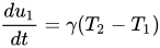
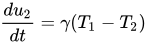
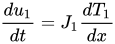
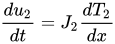
( this is for parallel flow in the same direction and opposite temperature gradients, but for counter-flow heat exchange countercurrent exchange the sign is opposite in the second equation in front of ), where is the thermal energy per unit length and γ is the thermal connection constant per unit length between the two pipes. This change in internal energy results in a change in the temperature of the fluid element. The time rate of change for the fluid element being carried along by the flow is:

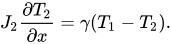
where is the "thermal mass flow rate". The differential equations governing the heat exchanger may now be written as:

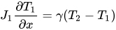
Since the system is in a steady state, there are no partial derivatives of temperature with respect to time, and since there is no heat transfer along the pipe, there are no second derivatives in x as is found in the heat equation. These two coupled first-order differential equations may be solved to yield:
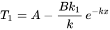
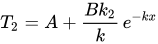
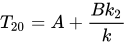
where , ,

(this is for parallel-flow, but for counter-flow the sign in front of is negative, so that if , for the same "thermal mass flow rate" in both opposite directions, the gradient of temperature is constant and the temperatures linear in position x with a constant difference along the exchanger, explaining why the counter current design countercurrent exchange is the most efficient )

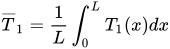
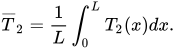
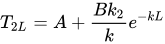
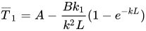
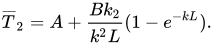
and A and B are two as yet undetermined constants of integration. Let and be the temperatures at x=0 and let and be the temperatures at the end of the pipe at x=L. Define the average temperatures in each pipe as:

Using the solutions above, these temperatures are:
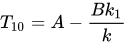
        

Choosing any two of the temperatures above eliminates the constants of integration, letting us find the other four temperatures. We find the total energy transferred by integrating the expressions for the time rate of change of internal energy per unit length:


By the conservation of energy, the sum of the two energies is zero. The quantity is known as the Log mean temperature difference, and is a measure of the effectiveness of the heat exchanger in transferring heat energy.

See also

[edit]

References

[edit]
[edit]
Revisions and contributorsEdit on WikipediaRead on Wikipedia
from Grokipedia
A heat exchanger is a device designed to efficiently transfer thermal energy between two or more fluids at different temperatures, typically without mixing them, across a separating solid surface such as tubes or plates.[1][2] Heat exchangers operate on the principles of convection and conduction, where heat flows from a hotter fluid to a cooler one through the intervening wall, enabling temperature equalization without direct fluid contact in most designs.[2] They are classified primarily by flow arrangement—such as parallel-flow, counterflow, or cross-flow—and by construction type, with the simplest being a single tube where hot and cold fluids flow in the same direction.[2] Key performance factors include the overall heat transfer coefficient, surface area, and fluid flow rates, which determine efficiency and capacity.[3] The most common industrial types are shell-and-tube heat exchangers, which consist of a bundle of tubes enclosed in a cylindrical shell for handling high-pressure fluids; plate heat exchangers, featuring stacked plates for compact, high-efficiency transfer in moderate-pressure applications; and air-cooled heat exchangers, using fins and fans for direct atmospheric cooling with air as the secondary fluid.[4] These designs are selected based on operating conditions like pressure, temperature, and fluid properties to optimize heat recovery and energy use.[3] Heat exchangers are indispensable in numerous sectors, including chemical plants, petrochemical refineries, power generation facilities, and natural gas processing for heating, cooling, and process stream temperature control.[5] They also play critical roles in everyday applications such as HVAC systems for building climate control, automotive radiators for engine cooling, refrigerators for food preservation, and waste heat recovery in industrial processes.[6] By facilitating efficient thermal management, heat exchangers contribute significantly to energy conservation and reduced operational costs across these fields.[5]

Fundamentals

Definition and purpose

A heat exchanger is a device or system designed to efficiently transfer thermal energy between two or more fluids at different temperatures, typically without allowing direct mixing to maintain fluid separation and prevent contamination.[7] The core components include the working fluids—such as gases or liquids—the separating surfaces that facilitate conduction (often tubes, plates, or fins), and dedicated inlets and outlets for each fluid stream to control flow paths.[2] This configuration enables controlled heat transfer primarily through conduction across the separating wall, supplemented by convection on either side.[3] The origins of heat exchangers trace back to early 19th-century innovations in industrial heating, with significant advancements in heat recovery systems. In 1857, the Siemens brothers, William and Friedrich, developed and patented a regenerative furnace that recovered waste heat from exhaust gases to preheat incoming combustion air, achieving fuel savings of 70-80% and laying foundational principles for modern heat exchanger designs.[8][9] This invention marked a pivotal shift toward energy-efficient thermal management in furnaces and boilers. Heat exchangers serve critical purposes in enhancing energy efficiency across various systems, including heat recovery from waste streams, precise temperature regulation in industrial processes, and overall energy conservation in applications like power generation and refrigeration cycles.[3] For instance, in power plants, they capture and reuse exhaust heat to boost cycle efficiency, while in refrigeration, they enable cooling by transferring heat from the working fluid to the surroundings.[7] Key performance metrics for heat exchangers include the overall heat transfer coefficient (U), which quantifies the rate of heat transfer per unit area per unit temperature difference across the system, accounting for convective and conductive resistances.[10] Complementing this is the effectiveness (ε), defined as the ratio of actual heat transferred to the maximum possible under ideal conditions, providing a dimensionless measure of how closely the device approaches theoretical limits. These metrics guide design and evaluation, emphasizing the balance between heat transfer enhancement and practical constraints like pressure drop.[11]

Thermodynamic principles

Heat transfer in heat exchangers primarily occurs through two modes: conduction across the separating wall and convection on the fluid sides. Conduction follows Fourier's law, which states that the heat flux $ q $ is proportional to the negative gradient of temperature, given by $ q = -k \nabla T $, where $ k $ is the thermal conductivity of the material. Convection, on the other hand, is governed by Newton's law of cooling, expressing the heat flux as $ q = h \Delta T $, where $ h $ is the convective heat transfer coefficient and $ \Delta T $ is the temperature difference between the fluid and the surface. The overall heat transfer rate $ Q $ in a heat exchanger is calculated using $ Q = U A \Delta T_{lm} $, where $ U $ is the overall heat transfer coefficient, $ A $ is the heat transfer surface area, and $ \Delta T_{lm} $ is the log mean temperature difference. This formulation arises from integrating the local heat transfer rate over the exchanger length, assuming steady-state conditions and constant fluid properties. For a differential element, the heat transfer is $ dQ = U dA (T_h - T_c) $, where $ T_h $ and $ T_c $ are the local hot and cold fluid temperatures. From energy balances on the fluids, $ dT_h = -dQ / (\dot{m}h c{p,h}) $ and $ dT_c = dQ / (\dot{m}c c{p,c}) $, leading to $ d(T_h - T_c) = -dQ \left( \frac{1}{\dot{m}h c{p,h}} + \frac{1}{\dot{m}c c{p,c}} \right) $. Substituting $ dQ = U (T_h - T_c) dA $ gives $ \frac{d(T_h - T_c)}{T_h - T_c} = - U dA \left( \frac{1}{\dot{m}h c{p,h}} + \frac{1}{\dot{m}c c{p,c}} \right) $. Integrating from inlet to outlet yields $ \Delta T_{lm} = (\Delta T_1 - \Delta T_2) / \ln(\Delta T_1 / \Delta T_2) $, where $ \Delta T_1 $ and $ \Delta T_2 $ are the temperature differences at the two ends. This derivation assumes no heat loss to the surroundings, constant $ U $, and negligible axial conduction or fluid property variations.[2][12] Under steady-state conditions without phase change, the energy balance for the heat exchanger requires conservation of energy, such that the heat lost by the hot fluid equals the heat gained by the cold fluid: $ \dot{m}h c{p,h} (T_{h,in} - T_{h,out}) = \dot{m}c c{p,c} (T_{c,out} - T_{c,in}) $. This equality holds because the system is isolated from external heat transfer, with all enthalpy change attributed to temperature variations at constant specific heats.[13] The effectiveness-NTU method provides an alternative approach for analyzing heat exchanger performance, particularly useful when outlet temperatures are unknown. The effectiveness $ \epsilon $ is defined as the ratio of actual heat transfer to the maximum possible heat transfer: $ \epsilon = Q / Q_{max} $, where $ Q_{max} = C_{min} (T_{h,in} - T_{c,in}) $ and $ C = \dot{m} c_p $ is the heat capacity rate, with $ C_{min} $ being the smaller of the two fluids'. The number of transfer units is $ NTU = U A / C_{min} $, and the capacity ratio is $ C_r = C_{min} / C_{max} $. For ideal cases, such as counterflow without phase change, $ \epsilon = \frac{1 - \exp[-NTU (1 - C_r)]}{1 - C_r \exp[-NTU (1 - C_r)]} $ when $ C_r < 1 $, and $ \epsilon = NTU / (1 + NTU) $ when $ C_r = 1 $. This method derives from nondimensionalizing the energy balance and differential equations, solving for outlet temperatures in terms of inlet conditions and exchanger parameters. It assumes the same conditions as the LMTD method, plus fully developed flow and no longitudinal heat conduction.[14][15] Common assumptions underlying these principles include steady-state operation, no heat loss to the surroundings, constant fluid properties (such as specific heat and thermal conductivity), and negligible changes in kinetic and potential energy. These simplifications enable analytical solutions but may require corrections for real-world applications involving variable properties or transient effects.[12][2]

Flow arrangements

Parallel flow

In parallel flow heat exchangers, also known as co-current flow arrangements, the hot and cold fluids enter the device at the same end and flow in the same direction through the exchanger, exiting together at the opposite end. This configuration is commonly implemented in double-pipe or concentric tube designs, where the fluids are separated by a conducting wall.[2] The temperature profiles in parallel flow exhibit a gradual convergence between the hot and cold fluid temperatures along the length of the exchanger, as heat transfers from the hotter to the cooler stream. Consequently, the outlet temperature of the cold fluid approaches but cannot exceed that of the hot fluid, preventing temperature crossover. This inherent limitation restricts the maximum effectiveness of the exchanger to 0.5 when the heat capacity rates of the two fluids are equal, as derived from the asymptotic behavior of the governing equations under infinite exchanger length.[14] The log mean temperature difference (LMTD) for parallel flow is a key parameter for performance evaluation, calculated using the formula:
ΔTlm=ΔT1ΔT2ln(ΔT1/ΔT2) \Delta T_{lm} = \frac{\Delta T_1 - \Delta T_2}{\ln(\Delta T_1 / \Delta T_2)}
where ΔT1=Th,iTc,i\Delta T_1 = T_{h,i} - T_{c,i} is the temperature difference at the inlet end and ΔT2=Th,oTc,o\Delta T_2 = T_{h,o} - T_{c,o} is the difference at the outlet end, with Th,iT_{h,i} and Th,oT_{h,o} denoting the hot fluid inlet and outlet temperatures, and Tc,iT_{c,i} and Tc,oT_{c,o} the corresponding cold fluid temperatures. This metric accounts for the varying temperature gradient along the flow path, enabling the heat transfer rate to be estimated as Q=UAΔTlmQ = UA \Delta T_{lm}, where UU is the overall heat transfer coefficient and AA is the surface area.[2] Parallel flow arrangements offer advantages such as simpler construction due to the unidirectional flow path, which facilitates easier manufacturing and maintenance. However, these exchangers suffer from lower thermal efficiency relative to counterflow designs, as the diminishing temperature difference reduces the driving force for heat transfer over the length. As a result, parallel flow is typically employed in shorter exchangers or applications where moderate heat recovery suffices and operational simplicity outweighs the need for maximal effectiveness.[16][17][18] The effectiveness (ϵ\epsilon) of a parallel flow heat exchanger, which represents the ratio of actual to maximum possible heat transfer, is determined using the effectiveness-NTU method with the equation:
ϵ=1exp[NTU(1+Cr)]1+Cr \epsilon = \frac{1 - \exp[-NTU (1 + C_r)]}{1 + C_r}
where NTU ($ = UA / C_{\min} $) is the number of transfer units, CrC_r ($ = C_{\min} / C_{\max} $) is the heat capacity rate ratio, and CminC_{\min} and CmaxC_{\max} are the minimum and maximum heat capacity rates of the fluids. This relation, derived from energy balance and assuming constant properties, highlights how effectiveness increases with NTU but is capped by the flow arrangement's constraints.[19]

Counterflow

In a counterflow heat exchanger, the hot and cold fluids enter at opposite ends and flow in opposite directions relative to each other, with the hot fluid entering where the cold fluid exits and the cold fluid entering where the hot fluid exits. This arrangement maximizes the temperature gradient along the entire length of the exchanger by maintaining a more uniform driving force for heat transfer compared to other configurations. The temperature profiles in counterflow allow the outlet temperature of the cold fluid to exceed the outlet temperature of the hot fluid, enabling the cold fluid exit temperature to approach the hot fluid inlet temperature closely, with effectiveness values reaching up to 1.0 under ideal conditions. This contrasts with parallel flow arrangements, where the converging temperatures limit the possible heat transfer. The log mean temperature difference for counterflow is defined using the same general formula as for parallel flow, ΔTlm=ΔT1ΔT2ln(ΔT1/ΔT2)\Delta T_{lm} = \frac{\Delta T_1 - \Delta T_2}{\ln(\Delta T_1 / \Delta T_2)}, but with ΔT1=Th,iTc,o\Delta T_1 = T_{h,i} - T_{c,o} and ΔT2=Th,oTc,i\Delta T_2 = T_{h,o} - T_{c,i}, where subscripts hh and cc denote hot and cold fluids, and ii and oo denote inlet and outlet, respectively; this yields a higher ΔTlm\Delta T_{lm} for given inlet and outlet temperatures. Counterflow arrangements provide the highest thermal efficiency of any basic flow configuration, making them particularly suitable for processes involving large temperature differences between the entering fluids. However, the substantial temperature changes across the exchanger can induce thermal stresses in the materials, and the opposing flow directions often necessitate more complex piping and structural designs. The effectiveness ϵ\epsilon for a counterflow heat exchanger, when the heat capacity rate ratio Cr=Cmin/Cmax<1C_r = C_{\min}/C_{\max} < 1, is given by
ϵ=1exp[NTU(1Cr)]1Crexp[NTU(1Cr)], \epsilon = \frac{1 - \exp[-NTU(1 - C_r)]}{1 - C_r \exp[-NTU(1 - C_r)]},
where NTU=UA/CminNTU = UA / C_{\min} is the number of transfer units, UU is the overall heat transfer coefficient, and AA is the heat transfer surface area. This relation is derived by nondimensionalizing the governing differential equations from the energy balances on both fluids. Starting with the incremental heat transfer dQ=ChdTh=CcdTcdQ = -C_h dT_h = C_c dT_c (with opposite signs due to directions), the local temperature difference is ΔT=ThTc\Delta T = T_h - T_c, and dQ=UdAΔTdQ = U dA \Delta T. For counterflow, the differential form becomes d(ΔT)ΔT=UdACmin(1Cr)\frac{d(\Delta T)}{\Delta T} = -\frac{U dA}{C_{\min}} (1 - C_r), which integrates over the exchanger area from ΔTi=Th,iTc,o\Delta T_i = T_{h,i} - T_{c,o} to ΔTo=Th,oTc,i\Delta T_o = T_{h,o} - T_{c,i}, yielding the LMTD expression; further nondimensionalization using ϵ=Q/Qmax\epsilon = Q / Q_{\max} and NTUNTU leads to the above closed-form solution after algebraic manipulation.

Crossflow

In a crossflow heat exchanger, the two fluids flow perpendicular to each other, with one fluid typically passing through tubes or channels while the other flows across the exterior, such as over fins or plates.[20] This arrangement is common in air-cooled heat exchangers, where air serves as the cooling medium crossing over finned tubes containing a hotter fluid, and in automotive radiators for efficient gas-liquid heat transfer.[21] Crossflow configurations vary based on whether the fluids are mixed or unmixed as they cross paths. In the both unmixed variant, both fluids are subdivided into multiple streams that do not mix within their respective flow paths, as seen in plate-fin heat exchangers where each fluid is confined to separate passages.[22] The one mixed-one unmixed variant occurs when one fluid (often the shell-side or external flow) mixes completely while the other remains segregated, common in tube banks with cross-flowing air. Both fluids mixed represents a simpler case where each fluid achieves uniform temperature across any cross-section perpendicular to flow, though less common due to reduced efficiency.[22] The temperature profiles in crossflow heat exchangers are inherently non-uniform, exhibiting local gradients that vary along both flow directions due to the perpendicular paths, preventing the use of a simple arithmetic mean for the temperature difference ΔT.[22] Instead, the log mean temperature difference (LMTD) requires a correction factor F to account for this deviation from ideal counterflow behavior. The LMTD correction factor F for crossflow is determined as a function of the temperature effectiveness P (the ratio of actual temperature change to maximum possible for the fluid with minimum capacity rate) and the capacity rate ratio R (C_min/C_max), often via graphical charts or analytical equations specific to the variant. For both fluids unmixed, F is derived from detailed solutions to the governing differential equations, ensuring accurate heat transfer rate Q = U A F ΔT_lm, where ΔT_lm is the counterflow LMTD.[23] Crossflow heat exchangers offer advantages in compactness, making them suitable for space-constrained applications, and enhanced performance with gases that have low heat transfer coefficients (h), as the cross-flow promotes turbulence on the gas side.[20] They are widely used in radiators and air conditioning systems for these reasons. However, they exhibit lower effectiveness than counterflow arrangements for the same number of transfer units (NTU), due to less optimal temperature driving forces.[20] Effectiveness ε in crossflow is calculated using the ε-NTU method, tailored to the variant. For both fluids unmixed, an approximate closed-form expression is:
ϵ=1exp[NTU0.22r0.22(exp(r0.78NTU0.78)1)]\epsilon = 1 - \exp\left[ \frac{\mathrm{NTU}^{0.22}}{r^{0.22}} \left( \exp(-r^{0.78} \mathrm{NTU}^{0.78}) - 1 \right) \right]
where r = C_min / C_max is the capacity ratio and NTU = U A / C_min is the number of transfer units based on the overall heat transfer coefficient U and area A. This formula, derived from numerical solutions to the energy balance equations, provides high accuracy for design and analysis.[24] For the one mixed-one unmixed case (mixed fluid with C_max), ε = (1 / R) (1 - exp[-R (1 - exp[-NTU])]), where R = C_min / C_max. Both mixed yields ε = NTU / (NTU + 1), a simpler but less efficient relation.[22]

Types

Shell and tube

The shell-and-tube heat exchanger features a bundle of straight tubes arranged within a cylindrical outer shell, where heat transfer occurs across the tube walls between the two fluids. The tubes are typically fixed at both ends to tube sheets, which separate the fluids and provide structural support, while the shell encloses the assembly to contain the external fluid. Baffles, spaced along the shell length, direct the shell-side fluid perpendicular to the tubes, promoting turbulence and enhancing heat transfer efficiency by creating multiple crossflow segments. This construction adheres to standards set by the Tubular Exchanger Manufacturers Association (TEMA), which specify dimensions, materials, and fabrication tolerances for mechanical integrity and performance.[25][26] On the tube side, one fluid flows longitudinally through the interior of the tubes, often in multiple passes via headers to increase velocity and heat transfer rates; configurations include straight tubes for multi-pass setups or U-shaped tubes for thermal expansion accommodation. The shell-side fluid enters through a nozzle, flows around the tube bundle in a crossflow pattern induced by the baffles, and exits via another nozzle, with baffle spacing and cut typically set at 20-25% of the shell diameter to balance heat transfer and pressure losses. This arrangement allows the shell side to approximate counterflow or crossflow conditions, depending on the number of baffles and passes.[27][28] Key advantages include high tolerance for elevated pressures and temperatures—up to several hundred bars and 500°C in robust designs—facilitating use with corrosive or high-pressure fluids; the modular tube bundle enables straightforward mechanical cleaning and maintenance by bundle removal; and scalability supports large thermal duties from kilowatts to megawatts. However, disadvantages encompass a larger footprint due to the extended shell length, elevated initial costs from material and fabrication requirements, and susceptibility to flow-induced tube vibrations if baffle spacing is inadequate.[29][30] TEMA standards classify variants by front head, shell, and rear head types, with common configurations including the BEU (fixed tube sheet with bonnet heads, suitable for clean fluids with minimal expansion issues), U-tube (allowing free tube expansion but limited to even-numbered passes and non-pure countercurrent flow), and floating head designs like AES or BE (removable bundles for dirty services and differential expansion up to 50 mm). Pressure drop on the tube side is primarily governed by frictional losses, expressed as ΔP ∝ f(Re, L/D), where f is the friction factor dependent on Reynolds number (Re), L is tube length, and D is diameter, often calculated using the Darcy-Weisbach equation for turbulent flows. Shell-side pressure drop employs the Bell-Delaware method, which accounts for crossflow through the bundle, baffle window losses, and leakage paths, providing a more accurate prediction than simpler models by incorporating correction factors for baffle spacing and leakage.[31][32] These exchangers are predominantly applied in oil refineries for crude preheating, fractionation, and product cooling, handling duties up to 100 MW with fluids like hydrocarbons at 200-400°C; in power plants, they serve as feedwater heaters, steam condensers, and turbine coolers, operating at scales exceeding 500 MW in utility boilers.[33][34]

Plate

A plate heat exchanger consists of a pack of thin, corrugated metal plates, typically stainless steel or titanium, stacked parallel to each other within a frame to create alternating flow channels for the hot and cold fluids. These channels are formed by the corrugations, which provide structural support and promote fluid mixing, while ports at the corners direct the fluids into and out of the appropriate channels. The plates are sealed using elastomeric gaskets, brazing, or welding to prevent cross-contamination and leakage between streams.[35] The flow paths in plate heat exchangers are designed for efficient thermal performance, often employing a multi-pass counterflow arrangement to achieve close temperature approaches between the fluids. Corrugated patterns, such as chevron or sinusoidal designs, induce high turbulence at relatively low Reynolds numbers, disrupting the boundary layer and enhancing convective heat transfer. This configuration allows for a high surface area-to-volume ratio, typically resulting in overall heat transfer coefficients ranging from 1000 to 5000 W/m²K, significantly higher than those of shell-and-tube exchangers.[36] Key advantages of plate heat exchangers include their compactness, occupying up to 65% less space than equivalent tubular designs due to the thin flow channels and high efficiency, as well as ease of maintenance in gasketed variants where individual plates can be added, removed, or cleaned without specialized tools. However, they are limited to moderate operating pressures, generally below 25 bar, and can suffer from gasket fouling or degradation in applications with particulate-laden or viscous fluids, reducing long-term reliability.[37][38] Variants of plate heat exchangers cater to diverse operational needs: gasketed plate-and-frame types offer expandability and straightforward disassembly for inspection, ideal for hygienic applications; brazed-plate designs provide a leak-proof, compact assembly suitable for refrigeration and higher pressures up to 30 bar; and welded-plate versions endure elevated temperatures above 200°C and corrosive environments but sacrifice modularity. Heat transfer performance is quantified through geometry-specific Nusselt number correlations, typically of the form Nu = C Re^m Pr^{1/3}, where coefficients C, m depend on the chevron angle and channel aspect ratio, emphasizing the role of turbulence in achieving elevated transfer rates.[39][36] These exchangers are widely applied in food processing for pasteurization and sterilization, where their cleanability ensures compliance with sanitary standards, and in HVAC systems for water chilling and heating, leveraging their modular nature to accommodate fluctuating loads in commercial buildings.[13]

Plate fin

Plate-fin heat exchangers consist of alternating layers of flat separator plates and secondary surface fins, typically made of aluminum, which are stacked and joined by brazing to form a compact core. The fins, which can be of various geometries such as plain, louvered, wavy, or offset strip, are placed between the plates to create narrow flow passages for the fluids, enhancing the heat transfer area while maintaining structural integrity. Side bars seal the edges of the passages, allowing for multiple independent streams to flow through the exchanger in a layered configuration.[40] The dominant flow arrangement in plate-fin heat exchangers is crossflow, where fluids pass perpendicular to each other between adjacent layers, though counterflow configurations are possible for specific designs. This setup enables multi-stream operation, with up to several independent fluid paths integrated within a single unit, making it suitable for complex thermal management needs. Advantages include exceptional compactness, with surface area densities reaching up to 3000 m²/m³, and superior performance for gases with low heat transfer coefficients, such as air, due to the extended finned surfaces that promote turbulence and increase the overall heat transfer rate. However, these exchangers are limited to operating pressures below 100 bar and temperatures typically ranging from -270°C to 800°C, and they suffer from challenges like difficult mechanical cleaning of the narrow passages and susceptibility to fin clogging from particulates or fouling.[41][40] Variants of plate-fin heat exchangers include air-cooled models, often used in automotive and power generation as air-cooled plate-fin heat exchangers (ACPHX), and specialized designs for cryogenic applications, where fin types like offset strip fins provide higher Colburn j-factors for improved heat transfer efficiency. Performance evaluation relies on the Colburn j-factor for the air-side heat transfer and the friction f-factor for pressure drop predictions, with the effectiveness-NTU method adapted for unmixed-unmixed crossflow conditions to account for the geometric complexities. These metrics, derived from empirical correlations in seminal works, allow designers to optimize fin geometry for specific duties, balancing thermal effectiveness often exceeding 0.95 with acceptable pressure losses.[42][43] Typical applications leverage the high compactness and multi-stream capability, such as in aircraft environmental control systems and engine cooling, where lightweight and space-efficient designs are critical, as well as in LNG liquefaction plants for cryogenic gas processing. In these uses, the exchangers handle low-temperature, multi-phase flows effectively, contributing to overall system efficiency in aerospace and petrochemical industries.[44][45]

Finned tube

Finned tube heat exchangers feature tubes fitted with external fins to augment the heat transfer surface area, particularly effective for applications involving gases with low convective heat transfer coefficients. The fins are typically attached to the outer surface of the tubes through methods such as extrusion, welding, or tension wrapping, and common configurations include annular (circular) fins spaced along the tube length, longitudinal fins running parallel to the tube axis, and spine (or needle) fins protruding perpendicularly for enhanced turbulence.[46][47][48] In these exchangers, the fluid flow arrangement generally places a liquid or higher-conductivity medium inside the tubes, while air or another gas flows externally in a crossflow pattern over the finned surfaces, promoting efficient heat exchange without direct fluid mixing. This design is prevalent in air-cooled systems, where the fins bridge the disparity in heat transfer rates between the tube-side and fin-side fluids.[49] The primary advantages of finned tube heat exchangers lie in their ability to significantly enhance heat transfer on the gas side by increasing the effective surface area, making them economical for large-scale outdoor installations such as air-cooled condensers. They also offer robustness for moderate pressures and temperatures, with compact designs relative to the heat duty achieved. However, disadvantages include susceptibility to dust and debris accumulation on the fins, which reduces efficiency over time and necessitates regular cleaning, as well as a larger overall footprint compared to unfinned alternatives due to the extended surfaces.[50][51][52] Variants of finned tube heat exchangers include steam-heated radiators, where steam flows through the tubes to warm surrounding air via the fins, and dry coolers that reject heat from process fluids to ambient air without water evaporation. Fin densities typically range from 10 to 20 fins per inch, balancing heat transfer enhancement with airflow resistance and fouling potential.[53][54][55] Thermal performance is governed by the fin efficiency ηf\eta_f, defined as the ratio of heat actually dissipated by the fin to the maximum that would be transferred if the entire fin surface were held at the tube base temperature — a theoretical ceiling approached only as fin material conductivity tends to infinity. For a fin of uniform cross-section, solving the one-dimensional conduction-convection equation with an adiabatic tip condition yields ηf=tanh(mLc)mLc\eta_f = \frac{\tanh(m L_c)}{m L_c}, where m=hPkAcm = \sqrt{\frac{h P}{k A_c}}, with hh the convective coefficient on the fin surface, PP the fin perimeter at the cross-section, kk the fin material thermal conductivity, and AcA_c the fin cross-sectional area; Lc=L+t2L_c = L + \frac{t}{2} is the corrected fin length, which extends the physical length LL by half the fin thickness tt to account approximately for heat loss from the fin tip without introducing a third boundary condition into the governing equation. Because a real exchanger surface consists of fins interspersed with unfinned tube wall, the quantity used in exchanger sizing is the overall surface efficiency ηo=1(AfAtot)(1ηf)\eta_o = 1 - \left( \frac{A_f}{A_{\mathrm{tot}}} \right) (1 - \eta_f), where AfA_f is the total fin area and AtotA_{\mathrm{tot}} is the combined fin and base area; ηo\eta_o then replaces ηf\eta_f when computing the overall heat transfer coefficient UU referred to the total outer surface, ensuring that the reduced effectiveness of the fins relative to the bare tube wall is correctly reflected in the thermal resistance network.[56] Typical applications encompass space heating through steam radiators in buildings, where natural or forced convection circulates warm air, and automotive radiators that cool engine coolant via forced airflow over the fins. These exchangers operate effectively in both forced convection modes, driven by fans, and natural convection setups for lower-duty requirements.[57][58][59]

Phase-change

Phase-change heat exchangers facilitate heat transfer primarily through latent heat associated with phase transitions between liquid and vapor states, enabling compact designs with high thermal efficiency. These devices are essential in processes where one fluid undergoes condensation from vapor to liquid or evaporation/boiling from liquid to vapor, absorbing or releasing significant energy without substantial temperature change.[60] The dominant heat transfer mechanism relies on the latent heat of vaporization, $ h_{fg} $, where the total heat load $ Q $ for pure phase change is given by $ Q = \dot{m} h_{fg} $, with $ \dot{m} $ as the mass flow rate of the phase-changing fluid.[61] In condensation, vapor cools and transitions to liquid on a cooler surface, with two primary mechanisms: filmwise and dropwise. Filmwise condensation forms a continuous liquid film that grows and drains under gravity, creating thermal resistance that limits heat transfer rates. Dropwise condensation, in contrast, produces discrete droplets that coalesce and slide off the surface, exposing more area for direct vapor contact and yielding up to 10 times higher heat transfer coefficients than filmwise modes, though achieving stable dropwise conditions requires specialized non-wetting surfaces.[62] For evaporation and boiling, heat transfer occurs as liquid vaporizes, with nucleate boiling involving bubble formation and detachment at the heated surface, enhancing convection through agitation, while film boiling features a stable vapor blanket that insulates the surface and reduces heat transfer efficiency.[63] Nucleate boiling dominates in practical applications due to its superior rates, typically up to the critical heat flux (CHF) point.[64] Design of phase-change heat exchangers must account for two-phase flow complexities, including pressure drops and void fractions. The Lockhart-Martinelli correlation predicts frictional pressure drop in two-phase flows by relating it to single-phase equivalents through a multiplier based on the Martinelli parameter, which incorporates viscosity and flow quality effects, aiding in sizing tubes and channels to avoid excessive losses.[65] Void fraction, the volume fraction of vapor in the mixture, influences flow regimes and heat transfer area, often modeled empirically for annular or bubbly flows in evaporators.[66] Additives like surfactants can enhance coefficients by up to 50% in some boiling scenarios by promoting nucleation sites, though they may increase fouling risks.[67] These exchangers offer advantages such as exceptionally high heat transfer coefficients, often exceeding 10,000 W/m²K in nucleate boiling, allowing for smaller footprints compared to sensible-only systems.[60] However, limitations include the critical heat flux, beyond which dryout occurs, sharply reducing performance and risking surface damage due to overheating, and potential dryout in low-liquid regions that exacerbates uneven heat distribution.[68][69] Typical applications include condensers in power plants, where steam condenses to liquid for reuse in Rankine cycles, and evaporators in refrigeration systems for vapor compression cycles.[70] In refrigeration, falling film evaporators distribute thin liquid films over surfaces for efficient evaporation with lower refrigerant charge and reduced pressure drop, contrasting flooded evaporators that immerse coils in a liquid pool for robust but bulkier operation.[71][72]

Direct contact

In direct contact heat exchangers, two fluids at different temperatures are brought into physical contact, allowing heat transfer through direct mixing without an intervening solid barrier. This configuration is particularly suited for immiscible fluids, such as gas-liquid or liquid-liquid pairs, where the absence of a separating wall eliminates conduction resistance across a surface.[73] Common setups include spray towers, where one fluid is atomized into droplets and sprayed into a counterflow of the other; venturi scrubbers, which use high-velocity gas streams to entrain liquid droplets for intimate mixing; and packed columns filled with random or structured packing materials to enhance the interfacial area between phases.[74] These designs promote thorough intermingling of the fluids, facilitating efficient heat exchange in processes where separation of the streams can be achieved downstream.[75] The primary mechanisms governing heat transfer in these exchangers are direct convection, driven by relative motion between the fluids, and often coupled mass transfer, especially in systems involving evaporation or absorption. For instance, in gas-liquid direct contact, heat is transferred via convective currents at the fluid interface, while latent heat effects may arise if phase change occurs, such as in evaporative cooling where water vaporizes into air.[76] This approach is most effective for immiscible fluids, as it leverages the large contact area created by dispersion (e.g., droplets or bubbles) to achieve high transfer rates without the need for complex geometries. The overall process relies on the creation and maintenance of a dynamic interface, where turbulence or relative velocity enhances mixing and heat dissipation. Direct contact heat exchangers offer several advantages, including structural simplicity due to the lack of separating surfaces, which reduces manufacturing and maintenance costs. They exhibit high heat transfer rates, particularly for gas streams, and are inherently self-cleaning because the absence of fixed surfaces prevents fouling accumulation.[74] However, these benefits come with drawbacks: the direct mixing necessitates downstream separation processes, such as decanters or cyclones, adding operational complexity and energy costs; moreover, they are limited to applications where the fluids are chemically compatible to avoid contamination or reactions.[75] Variants of direct contact exchangers include gas-liquid types, commonly used in cooling towers where hot water is cooled by ambient air through evaporation and sensible heat transfer, and liquid-liquid types, such as quenchers employed in chemical processing to rapidly cool hot liquids with a colder immiscible fluid. In gas-liquid systems, configurations like spray chambers dominate for large-scale air cooling, while liquid-liquid variants often use jet or impingement designs for high-intensity mixing in smaller units.[74] Performance in direct contact heat exchangers is characterized by heat transfer coefficients that depend on factors such as relative velocity between phases, fluid properties (viscosity, density, thermal conductivity), and the effective interfacial area. Higher velocities generally increase the coefficient by promoting turbulence and droplet breakup, leading to greater contact area, though excessive speeds can cause entrainment losses.[76] The overall heat transfer rate is thus a function of this area and the temperature driving force, often modeled empirically for specific configurations to predict efficiency.[73] Typical applications encompass cooling towers in power plants and industrial facilities, where water is directly contacted with air to reject waste heat; desalination processes, utilizing direct contact for multi-stage flash evaporation; and humidification or dehumidification systems in air conditioning, where moist air interacts with liquid desiccants. These uses highlight their role in energy-intensive operations requiring robust, low-maintenance heat rejection.[74]

Microchannel

Microchannel heat exchangers feature channels with hydraulic diameters typically less than 1 mm, enabling ultra-compact designs for enhanced heat transfer efficiency in applications requiring miniaturization. These devices are constructed using methods such as chemical etching, laser machining, or extrusion of micro-tubes and plates, often from aluminum alloys that facilitate vacuum brazing for assembly into multi-layer stacks.[77] The multi-microchannel configuration typically employs parallel flow paths, where fluid motion is dominated by laminar regimes at low Reynolds numbers due to the small scale, promoting high surface-to-volume ratios for improved thermal performance.[78] Key advantages include exceptional compactness and high overall heat transfer coefficients, achieving volumetric heat transfer densities up to 10,000 W/m³K, alongside reduced refrigerant or coolant inventory compared to conventional exchangers.[79] This makes them ideal for systems where space and material efficiency are critical. However, disadvantages encompass elevated pressure drops from viscous effects in narrow channels, necessitating precise manufacturing tolerances to avoid uneven flow distribution, and heightened susceptibility to clogging from particulates or fouling.[80] Variants often incorporate enhancements like louvered fins or offset strip configurations to augment air-side heat transfer, particularly in automotive air conditioning or electronics cooling modules.[81] Performance characteristics are influenced by strong entrance effects in short channels, with the Nusselt number for fully developed laminar flow in circular microchannels approximating 8.23 under constant heat flux boundary conditions.[69] Emerging prominently since the early 2000s, these exchangers find typical applications in electric vehicle thermal management, data center cooling, and compact refrigeration units, driving advancements in energy-efficient miniaturization.[82]

Design and selection

Key criteria

The selection of a heat exchanger begins with evaluating fluid characteristics, which directly impact heat transfer efficiency and equipment longevity. Viscosity affects flow dynamics and pressure drop, with higher viscosity fluids requiring designs that minimize resistance, such as larger tube diameters in shell-and-tube exchangers. Thermal conductivity determines the rate of heat transfer across the fluid boundary layer, where fluids with low conductivity, like oils, necessitate enhanced surface areas or extended designs. Corrosiveness of the fluids dictates material choices to prevent degradation, ensuring compatibility with alloys like stainless steel or titanium for acidic or saline environments. Fouling tendency, arising from particulate buildup or chemical deposition, favors robust types like shell-and-tube exchangers for dirty or particulate-laden fluids, as they allow easier mechanical cleaning compared to plate designs.[83][84][85] Operating conditions further guide the choice by defining the exchanger's operational envelope. Temperature and pressure ranges must align with the design limits, for instance, high-pressure applications often suit shell-and-tube configurations due to their structural integrity, while low-pressure systems may use plate exchangers for compactness. Flow rates influence velocity and turbulence, with high-flow scenarios demanding low-pressure-drop designs to avoid excessive pumping costs. The phase of the fluids—single-phase (liquid-liquid or gas-gas) or two-phase (involving boiling or condensation)—requires specialized handling, such as enhanced nucleation sites in evaporators for two-phase flows to promote efficient phase change.[83][84][13] Economic factors balance upfront and ongoing expenses in the selection process. Initial costs vary by type, with shell-and-tube exchangers typically more expensive due to fabrication complexity but justified for durable, high-duty applications. Space constraints favor compact options like plate or microchannel designs for installations with limited footprint, such as in offshore platforms. Lifecycle considerations include pumping power requirements, where designs minimizing pressure drop reduce energy consumption over time, and maintenance accessibility lowers long-term operational costs.[84][83][86] Performance targets establish the functional benchmarks for selection. The required heat transfer rate (Q) must be met within specified outlet temperatures, guiding the choice toward high-efficiency types like plate exchangers for close temperature approaches. Allowable pressure drop (ΔP) limits the design to prevent system overload, often prioritizing smooth-flow paths in finned-tube setups. These targets ensure the exchanger achieves desired thermal performance without compromising system integrity.[83][84] Environmental considerations emphasize sustainability and safety. Material compatibility prevents reactions that could lead to leaks or emissions, with non-reactive coatings or alloys selected for hazardous fluids. Leak prevention is paramount in applications involving toxic or flammable substances, favoring double-wall constructions or monitored designs to contain any breaches. Energy-efficient selections, such as those with high overall heat transfer coefficients, reduce operational carbon footprints by lowering utility demands.[84][83] The selection process follows a systematic, step-by-step approach to match the duty to an appropriate type. First, define the process requirements, including fluids, heat duty, and phases, to identify potential fouling or corrosiveness issues. Second, assess operating conditions like temperatures, pressures, and flow rates to narrow options based on design limits. Third, evaluate performance targets such as Q, ΔP, and outlet temperatures to ensure feasibility. Fourth, incorporate economic and environmental factors, comparing costs, space, and material needs. Finally, iterate by referencing exchanger types—e.g., opting for shell-and-tube for dirty fluids prone to fouling—while verifying compatibility through vendor data or simulations before finalizing.[85][84][87]

Sizing and performance calculations

Sizing and performance calculations for heat exchangers involve determining the required surface area and predicting operational efficiency based on heat transfer rates, fluid properties, and geometric configurations. The primary methods are the logarithmic mean temperature difference (LMTD) approach for initial design and the effectiveness-NTU (ε-NTU) method for performance evaluation, both relying on empirical correlations for heat transfer coefficients and pressure losses. These calculations often require iterative procedures to balance thermal performance with hydraulic constraints, such as pressure drop limitations.[88] The LMTD method calculates the heat exchanger area AA using the equation
A=QUΔTlm A = \frac{Q}{U \Delta T_{lm}}
where QQ is the heat transfer rate, UU is the overall heat transfer coefficient, and ΔTlm\Delta T_{lm} is the logarithmic mean temperature difference defined as
ΔTlm=ΔT1ΔT2ln(ΔT1/ΔT2) \Delta T_{lm} = \frac{\Delta T_1 - \Delta T_2}{\ln(\Delta T_1 / \Delta T_2)}
with ΔT1\Delta T_1 and ΔT2\Delta T_2 being the temperature differences at the exchanger ends. This method assumes known inlet and outlet temperatures and is suitable for sizing when flow arrangement effects on ΔTlm\Delta T_{lm} are accounted for via correction factors. Since UU depends on flow velocities and thus on the area, an initial guess for UU is used, followed by iteration using correlations for convective coefficients until convergence.[15][83] The ε-NTU method is preferred for rating existing exchangers or when outlet temperatures are unknown, as it directly relates performance to dimensionless parameters. Here, effectiveness ϵ\epsilon is the ratio of actual heat transfer to maximum possible, given by ϵ=Q/(Cmin(Th,inTc,in))\epsilon = Q / (C_{min} (T_{h,in} - T_{c,in})), where CminC_{min} is the minimum fluid heat capacity rate. The number of transfer units is NTU = UA/CminUA / C_{min}, and ϵ\epsilon is expressed as a function of NTU and the capacity ratio Cr=Cmin/CmaxC_r = C_{min}/C_{max}, such as for counterflow ϵ=1exp[NTU(1Cr)]1Crexp[NTU(1Cr)]\epsilon = \frac{1 - \exp[-NTU(1 - C_r)]}{1 - C_r \exp[-NTU(1 - C_r)]}. This approach facilitates comparison across configurations without specifying temperatures.[89][90] The overall heat transfer coefficient UU is determined from
1U=1hi+xk+1ho+Rf \frac{1}{U} = \frac{1}{h_i} + \frac{x}{k} + \frac{1}{h_o} + R_f
where hih_i and hoh_o are inner and outer convective coefficients, x/kx/k is wall conduction resistance, and RfR_f includes brief fouling allowances. Convective coefficients derive from Nusselt number correlations; for turbulent tube-side flow (Re > 10,000, 0.7 < Pr < 160), the Dittus-Boelter equation gives Nu=0.023Re0.8Pr0.4Nu = 0.023 Re^{0.8} Pr^{0.4} for heating or Nu=0.023Re0.8Pr0.3Nu = 0.023 Re^{0.8} Pr^{0.3} for cooling, with h=Nuk/Dh = Nu k / D. Shell-side coefficients use more complex correlations involving baffle spacing and flow patterns.[88][91][92][93] Pressure drop calculations ensure feasibility, particularly for tube-side flow in shell-and-tube exchangers, using the Darcy-Weisbach equation
ΔP=fLDρv22+Kρv22 \Delta P = f \frac{L}{D} \frac{\rho v^2}{2} + \sum K \frac{\rho v^2}{2}
where ff is the friction factor (e.g., f=0.184Re0.2f = 0.184 Re^{-0.2} for smooth tubes), L/DL/D is the length-to-diameter ratio, ρ\rho and vv are density and velocity, and KK terms account for minor losses from bends and entrances. Shell-side pressure drop involves empirical methods considering cross-flow and baffle-induced turbulence, often yielding ΔP0.5\Delta P \approx 0.5 to 5 psi for typical designs. Optimization trades higher velocities for enhanced UU against increased ΔP\Delta P, targeting allowable drops of 1-2 psi per pass.[88][94][95][96] Commercial software like HTRI Xchanger Suite and Aspen EDR facilitate iterative multi-pass designs by integrating these methods with proprietary correlations for complex geometries. For instance, HTRI simulates shell-and-tube performance using over 100,000 experimental data points for UU and ΔP\Delta P predictions.[97][98] As a representative example, consider sizing a counterflow heat exchanger transferring Q=1Q = 1 MW from water at 100°C inlet to 60°C outlet cooling air from 20°C to 50°C, with U500U \approx 500 W/m²K. The ΔTlm=45.5°C\Delta T_{lm} = 45.5°C yields A44A \approx 44 m²; iterating with Dittus-Boelter for tube-side hih_i and air-side correlations confirms viability with ΔP<1\Delta P < 1 kPa.[88]

Applications

Industrial processes

In the petrochemical industry, heat exchangers play a critical role in processes such as crude oil preheating and distillation, where shell-and-tube designs are commonly employed to recover heat from hot product streams and preheat incoming crude oil, typically raising its temperature from ambient to around 300-350°C before furnace entry.[99] These units, often arranged in a preheat train, can recover up to 80-90% of available heat, minimizing fuel consumption in distillation furnaces.[100] In distillation columns, overhead condensers use similar shell-and-tube heat exchangers to cool and condense vapors by transferring heat to the cold crude feed, enhancing overall energy efficiency in fractionation.[101] In power generation, feedwater heaters utilize closed-cycle heat exchangers to preheat boiler feedwater using steam extracted from turbines, improving cycle efficiency by 5-10% in conventional steam plants.[102] Steam generators, particularly in nuclear and fossil fuel plants, employ once-through or recirculating heat exchangers to produce high-pressure steam from heat sources, operating at temperatures up to 550°C.[103] For waste heat recovery, organic Rankine cycle (ORC) systems integrate compact heat exchangers, such as plate-fin types, to convert low-grade heat (80-200°C) from exhaust gases into electricity, achieving efficiencies of 10-20% in industrial settings.[104] In the food and pharmaceutical sectors, plate heat exchangers are widely used for pasteurization, where they rapidly heat liquids like milk to 72°C for 15 seconds to eliminate pathogens while preserving quality, followed by regenerative cooling.[105] Sterilizers employ tubular or scraped-surface heat exchangers to process heat-sensitive products at 120-140°C under aseptic conditions, ensuring microbial safety in pharmaceutical formulations.[106] Sanitary designs, featuring smooth surfaces, crevice-free welds, and materials like 316L stainless steel, comply with hygienic standards to prevent contamination and facilitate cleaning-in-place (CIP) protocols.[105] Heat exchanger networks in industrial processes are optimized using pinch analysis, a thermodynamic method that identifies the pinch point—the temperature where heat recovery is most constrained—and minimizes utility requirements by matching hot and cold streams. This approach typically targets a minimum approach temperature of 5-10°C across exchangers to balance heat transfer rates with economic feasibility, reducing external heating and cooling demands by 20-40% in integrated systems.[107] Case studies in refineries demonstrate significant energy savings from heat recovery; for instance, retrofitting preheat trains with advanced exchanger networks has achieved 20-30% reductions in fuel use by capturing waste heat from distillation and cracking units, as seen in U.S. facilities optimizing for lower carbon emissions.[103] Such implementations highlight the role of heat exchangers in process integration, yielding payback periods of 1-3 years through decreased operational costs.[108] Challenges in industrial heat exchangers include corrosion from acidic environments, such as naphthenic acids in crude oils, which accelerate material degradation at processing temperatures of 220-400°C, necessitating corrosion-resistant alloys like duplex stainless steels. At high temperatures exceeding 500°C, such as in steam generators or pyrolysis units, oxidation and creep become prevalent, requiring advanced materials like nickel-based superalloys to maintain structural integrity and prevent failures.[109] These issues demand rigorous material selection and monitoring to ensure long-term reliability in harsh conditions.[110]

HVAC and refrigeration

In heating, ventilation, air conditioning (HVAC), and refrigeration systems, heat exchangers play a central role in transferring thermal energy to maintain comfortable indoor environments and preserve perishable goods. These devices facilitate efficient heat absorption and rejection, primarily through evaporators and condensers in vapor-compression cycles, where refrigerants undergo phase changes to enable cooling or heating. Air coils, often finned-tube designs, enhance heat transfer between air streams and refrigerants or chilled fluids, improving overall system performance in both residential and commercial applications.[70][111] In HVAC systems, chillers commonly employ plate or shell-and-tube heat exchangers to cool water for distribution to fan coil units, with plate designs offering up to five times higher efficiency due to enhanced turbulence and surface area compared to shell-and-tube configurations. Fan coils integrate these exchangers as cooling or heating elements, circulating either chilled water from a central chiller or refrigerant in direct expansion (DX) systems; DX setups are preferred for smaller zones due to their simplicity and lower initial costs, while chilled water systems scale better for large buildings by minimizing refrigerant charge and enabling centralized control. Phase-change processes in these cycles occur primarily in the evaporators and condensers.[112][113][114][70] Refrigeration applications leverage specialized heat exchangers for commercial and cryogenic uses. In commercial refrigeration, microchannel heat exchangers (MCHEs) dominate due to their compact size and 5-15% higher energy efficiency over traditional finned-tube coils, achieved through reduced pressure drops and increased refrigerant-side heat transfer via numerous small channels. Cryogenic refrigeration employs high-performance exchangers, such as plate-fin or coiled-tube designs, to handle extreme low temperatures below -150°C, ensuring minimal heat ingress in processes like liquefied natural gas production or superconducting systems.[115][116][117] The performance of these systems is quantified by the coefficient of performance (COP), which measures useful heating or cooling output per unit of electrical input; optimized heat exchangers can boost COP by 25-45% through improved heat transfer rates and reduced fouling. Post-2020 regulations, including the American Innovation and Manufacturing Act, mandate low global warming potential (GWP) refrigerants with GWP below 700 for new HVAC equipment by 2025, necessitating exchanger redesigns for compatibility with mildly flammable alternatives like R-32 or R-454B to maintain efficiency without compromising safety.[118][119][120][121] Emerging trends emphasize variable capacity compressors integrated with heat exchangers for modulated operation, reducing energy use by matching load demands, alongside smart controls that use sensors and AI for predictive optimization. Heat recovery via run-around coils or energy recovery ventilators captures exhaust heat for preheating incoming air, yielding up to 30% energy savings in commercial HVAC. AHRI standards, such as AHRI 400 for liquid-to-liquid exchangers, provide performance ratings ensuring verified efficiency, with typical HVAC chiller capacities ranging from 1 to 1000 kW to suit diverse building scales.[122][123][124][125]

Biological and natural systems

In biological systems, heat exchangers facilitate efficient temperature regulation and resource conservation through specialized anatomical structures that enable countercurrent or crossflow heat transfer. These natural mechanisms, evolved over millions of years, optimize energy use by minimizing thermal gradients and maximizing exchange efficiency, often achieving near-ideal performance comparable to engineered counterflow designs. Such adaptations are prevalent across taxa, from mammals to fish, underscoring their role in homeostasis and survival in diverse environments. In humans, countercurrent heat exchange occurs in the limbs, where arteries and veins run parallel, allowing warm arterial blood to transfer heat to cooler returning venous blood, thereby reducing heat loss to the environment and conserving core body temperature during exposure to cold. Similarly, in the upper respiratory tract, vascular networks in the nasal passages and trachea form countercurrent arrangements that warm inhaled air using outgoing warm blood and recover heat from exhaled air, enhancing respiratory efficiency while minimizing thermal loss—particularly vital during respiration in varying ambient temperatures. Birds and fish employ counterflow heat exchangers via the rete mirabile, a network of arterial and venous capillaries arranged in parallel to enable precise thermoregulation. In birds, such as the bill of the Australian black swan, the rete mirabile facilitates heat dissipation from arterial blood to cooler venous blood returning from the extremities, preventing overheating during flight or in hot climates. Fish utilize similar retia in their swim bladders or muscles to retain metabolic heat, allowing species like tuna to maintain elevated body temperatures for enhanced swimming performance in cold ocean depths. Fish gills, operating as crossflow exchangers, further demonstrate this principle: water flows over lamellae perpendicular to blood flow within, enabling oxygen uptake and heat retention; for instance, in rainbow trout, this setup achieves up to 80% oxygen extraction efficiency while minimizing heat loss to aquatic environments. Marine mammals, including seals and whales, integrate countercurrent heat exchange in nasal passages to conserve heat during prolonged dives. As cold seawater enters the nostrils, it passes over a vascular countercurrent network where outgoing warm air preheats the incoming water, reducing conductive heat loss by up to 90% and preventing nasal tissue freezing. Blubber layers in these animals serve as an insulating barrier analogous to a heat exchanger, with vascular counterflow within the subcutaneous fat minimizing peripheral heat dissipation while allowing core temperature stability. The carotid rete in mammals, such as cats and sheep, provides brain-specific cooling: cool venous blood from the nasal mucosa or skin flows parallel to warm carotid arteries, abstracting heat to protect neural tissue from hyperthermia during exertion. These biological heat exchangers confer evolutionary advantages by enhancing energy efficiency and thermal homeostasis, enabling organisms to thrive in extreme conditions—such as deep-sea pressures or arid deserts—without the metabolic costs of constant heating or cooling. For example, countercurrent systems in polar birds reduce heat loss by 50-70% compared to parallel flow alternatives, directly impacting survival rates. This efficiency has inspired biomimicry in engineering, where designs mimicking fish gill plates or rete mirabile networks improve heat transfer in compact devices like medical dialyzers or microelectronics cooling systems, drawing from principles observed in nature to achieve higher performance with lower material use.

Operation and maintenance

Fouling mechanisms

Fouling in heat exchangers involves the accumulation of unwanted deposits on heat transfer surfaces, leading to increased thermal resistance and degraded performance over time.[126] The primary types of fouling include scaling, precipitation, particulate, biological, and corrosion fouling.[127] Scaling arises from the inverse solubility of minerals such as calcium sulfate or silica at elevated temperatures, where solubility decreases as temperature rises, promoting deposition.[128] Precipitation fouling occurs when dissolved salts exceed their solubility limits due to concentration or temperature changes, forming crystalline layers.[129] Particulate fouling results from the settling of suspended solids like dirt or rust particles onto surfaces, particularly in low-flow regions.[130] Biological fouling involves the growth of microorganisms, algae, or biofilms that adhere and proliferate, often in aqueous systems with nutrients.[131] Corrosion fouling stems from the oxidation or chemical degradation of the heat exchanger material, releasing metal oxides that deposit as a layer.[127] The mechanisms of fouling are governed by deposition kinetics, where foulants are transported from the bulk fluid to the surface via diffusion, inertia, or sedimentation, influenced by the boundary layer near the wall.[126] In the boundary layer, reduced flow velocity allows foulants to accumulate, increasing the deposit thickness $ t_f $. The resulting fouling resistance $ R_f $ is calculated as $ R_f = \frac{t_f}{k_f} $, where $ k_f $ is the thermal conductivity of the foulant layer, which adds to the overall thermal resistance and diminishes heat transfer.[126] Deposition rates depend on mass transfer coefficients, with thicker boundary layers at low velocities enhancing fouling propensity.[132] Several factors exacerbate fouling: low fluid velocity thickens the boundary layer, reducing shear forces that could remove deposits; high temperatures accelerate chemical reactions and precipitation; and fluid chemistry, such as high mineral content in hard water, promotes scaling.[126] For instance, in cooling water systems, elevated hardness levels lead to rapid calcium carbonate scaling.[128] Fouling impacts performance by reducing the overall heat transfer coefficient $ U $, potentially by up to 50% in severe cases, and increasing pressure drop $ \Delta P $ due to narrowed flow paths.[133] Many fouling processes follow asymptotic models, where the deposition rate slows as the layer thickens, approaching a steady-state resistance limited by removal mechanisms like erosion.[130] To predict fouling, standards such as those from the Tubular Exchanger Manufacturers Association (TEMA) provide empirical fouling factors; for example, 0.0002 m²K/W is typical for treated cooling water.[134] These factors are incorporated into design calculations for the overall heat transfer coefficient $ U $ to account for expected performance degradation.[133] Initial designs can incorporate features like accessible tube sheets or enhanced turbulence to facilitate cleanability and limit fouling accumulation.[135]

Monitoring techniques

Monitoring techniques for heat exchangers primarily focus on detecting and assessing fouling or degradation to maintain operational efficiency and prevent failures. Performance tracking is a fundamental approach, involving the continuous measurement of inlet and outlet temperatures and flow rates for both process and cooling fluids. These parameters allow for the real-time calculation of the overall heat transfer coefficient (U) or effectiveness (ε), which indicate degradation when values deviate from initial clean conditions.[136][137] Non-invasive methods enable assessment without system shutdown. Ultrasonic thickness gauging measures wall thinning due to corrosion by sending high-frequency sound waves through the metal, providing precise data on material loss.[138] Monitoring pressure drop trends across the exchanger detects fouling accumulation, as deposits narrow flow paths and increase resistance.[139] Invasive techniques require partial or full access to internal components. Endoscopy uses flexible borescopes to visually inspect tube interiors for deposits, cracks, or blockages.[140] Sampling involves extracting process fluid or deposits for laboratory analysis to identify fouling composition, such as scale or particulates. Thermal imaging identifies hotspots on external surfaces, signaling internal issues like uneven flow or localized overheating.[139][141] Online monitoring systems integrate sensors for continuous data collection. Resistance temperature detectors (RTDs) measure temperatures at multiple points, while differential pressure (DP) cells track flow restrictions.[142] Recent advancements include AI-driven predictive analytics, which analyze sensor data to forecast fouling rates and recommend interventions, emerging as a post-2020 trend in industrial applications.[143] Diagnostics compare current performance against design specifications, such as deviations in heat duty (Q), where reduced transfer rates signal issues. Threshold alerts are set for anomalies, for example, a 10% drop in U prompting further investigation.[144] Industry standards guide monitoring practices, including API 660 for shell-and-tube heat exchanger fabrication and inspection requirements, which recommend intervals based on service conditions, often aligned with API 510 for in-service pressure vessel inspections (e.g., external every 3-5 years, internal every 5-10 years).[145]

Cleaning and maintenance strategies

Heat exchangers require regular cleaning and maintenance to mitigate fouling, restore thermal efficiency, and extend operational life. Effective strategies balance downtime, cost, and safety while addressing specific fouling types such as scale, biological growth, or particulates. These approaches are informed by monitoring techniques that detect performance degradation, such as increases in pressure drop or decreases in heat transfer rates.[146] Offline cleaning methods involve shutting down the unit for thorough deposit removal and are suitable for severe fouling. Mechanical techniques include brushing or scraping surfaces to dislodge deposits, often used on tube interiors, and high-pressure hydroblasting, which employs water jets at 10,000–40,000 psi to erode scale without chemicals. Chemical cleaning circulates solvents like hydrochloric acid for inorganic scale or EDTA (ethylenediaminetetraacetic acid) chelants for biological and metal oxide fouling, achieving up to 85% removal efficiency in shell-and-tube designs. These methods typically restore the overall heat transfer coefficient (U) to near-design values but require isolation, draining, and post-clean rinsing to prevent corrosion.[147][148][146] Online cleaning enables deposit removal without full shutdown, minimizing production losses in continuous processes. Common techniques include sponge ball circulation, where soft balls are pumped through tubes to scrub fouling gently, or bullet cleaning with rigid projectiles for harder deposits in power plant condensers. For finned-tube exchangers, vibrational methods apply acoustic or mechanical agitation to dislodge particulates from air-side surfaces. These approaches maintain 70–90% of design performance during operation but are less effective against tenacious biofouling.[146][149] Preventive maintenance focuses on reducing fouling propensity through upstream interventions and routine scheduling. Water treatment strategies, such as softening to remove hardness ions or adding antiscalants, can limit mineral deposition in cooling systems by 50% or more. Installing strainers or filters captures particulates before they enter the exchanger, while scheduled partial shutdowns every 6–12 months allow targeted cleaning. These measures extend exchanger life to 20–30 years for well-maintained shell-and-tube units.[150][151] Specialized strategies like clean-in-place (CIP) systems are particularly effective for plate heat exchangers, circulating cleaning agents through the unit without disassembly. CIP involves sequential rinses with alkaline detergents for organics, acids for scales, and sanitizers, restoring efficiency in food and pharmaceutical applications with minimal labor. Overall, maintenance protocols emphasize health, safety, and environmental (HSE) compliance, including personal protective equipment, confined space entry procedures, and proper chemical handling to avoid hazards during cleaning.[152][153] Cost-benefit analysis guides cleaning frequency, with return on investment (ROI) typically realized when U drops by 20% or more, as this threshold often doubles energy costs due to reduced efficiency. Optimization models suggest cleaning intervals of 1–5 years based on fouling rates, balancing downtime costs (e.g., lost production) against cleaning expenses (5–10% of exchanger value annually).[154][155] Emerging technologies enhance precision and sustainability in maintenance. Robotic cleaners, such as pipeline inspection gauges (PIGs) adapted for tubes, navigate internals autonomously to remove over 90% of fouling via high-pressure lancing, reducing human exposure in hazardous environments. Enzymatic treatments, using proteases and amylases, target biofouling in dairy plate exchangers by breaking down protein and starch deposits, achieving 78% removal comparable to chemical methods with lower environmental impact.[156][157][158]

Manufacturing and standards

Materials and construction

Heat exchangers are fabricated using materials chosen for their compatibility with operating fluids, temperatures, and pressures to ensure durability and efficiency. Carbon steel serves as a cost-effective base material for non-corrosive environments, while stainless steels such as 304 and 316 provide enhanced resistance to oxidation and moderate corrosion in aqueous systems.[159][160] Titanium, particularly Grade 2, offers superior protection against chloride-induced pitting and crevice corrosion in seawater or brackish applications.[161][162] For highly aggressive conditions involving acids or chlorides, nickel-based alloys like Hastelloy C276 are selected due to their exceptional resistance to localized corrosion and thermal conductivity around 9.8-11 W/mK.[163] Polymers and composites, such as reinforced plastics, are utilized in low-temperature, low-pressure systems for their chemical inertness and reduced weight, though with lower thermal conductivities typically below 1 W/mK.[164] Material selection prioritizes corrosion resistance to mitigate pitting and crevice attack, high thermal conductivity for metals to optimize heat transfer, and mechanical properties including yield strengths over 200 MPa to endure pressure differentials and vibrations.[165][163] Construction techniques emphasize joining methods that maintain structural integrity and minimize thermal barriers. Tungsten Inert Gas (TIG) welding is widely applied for tube-to-tubesheet connections in shell-and-tube designs, providing precise, high-quality welds resistant to leaks under high pressure.[166][167] Brazing, often vacuum-based, joins aluminum fins and plates in compact plate-fin exchangers, enabling complex geometries without distorting thin sections.[168] Cladding with alloys like Alloy 625 overlays carbon steel components to impart corrosion resistance in sour service environments, extending service life without full material replacement.[169] Fabrication processes involve precise forming to enhance heat transfer surfaces. Tube rolling expands seamless tubes into drilled tubesheets, creating a mechanical interlock that withstands thermal expansion differentials.[167] Plate stamping forms corrugated patterns on thin metal sheets for gasketed plate exchangers, increasing turbulence and surface area for improved efficiency.[170] Quality assurance incorporates non-destructive testing (NDT), including dye penetrant inspection, to identify surface-breaking defects in welds and castings post-fabrication.[171][172] Advancements since 2015 have introduced additive manufacturing, or 3D printing, for prototyping intricate designs that reduce weight by up to 30% while boosting gravimetric power density.[173][174] Nanomaterial coatings, such as titanium dioxide or graphene-based layers, enhance surface hydrophobicity to resist fouling accumulation, maintaining long-term thermal performance.[175] Lifecycle considerations focus on mitigating fatigue from cyclic thermal loading and creep deformation at temperatures above 500°C, which can compromise tube integrity over 10-20 years of operation.[176][177] Typical capital costs for shell-and-tube heat exchangers range from $100 to $500 per m² of heat transfer area, balancing initial investment with extended service life through robust material choices.[178]

Regulatory compliance

Heat exchangers, as pressure-containing equipment, must comply with a range of international and regional codes to ensure structural integrity and operational safety. The American Society of Mechanical Engineers (ASME) Boiler and Pressure Vessel Code (BPVC), particularly Section VIII, establishes rules for the design, fabrication, inspection, and testing of pressure vessels, including many types of heat exchangers, to prevent failures under internal or external pressure. For shell-and-tube configurations, the Tubular Exchanger Manufacturers Association (TEMA) provides specific standards that classify exchanger types and specify mechanical design, tolerances, and performance criteria, complementing broader pressure vessel codes. In the petroleum and refinery sectors, the American Petroleum Institute (API) Standard 660 outlines requirements for shell-and-tube heat exchangers, focusing on materials, fabrication, and testing to withstand corrosive and high-temperature environments typical in oil processing. Safety regulations emphasize protection against hazards such as overpressure and leaks. In the European Union, the Pressure Equipment Directive (PED) 2014/68/EU mandates conformity assessment for heat exchangers based on pressure and volume categories, requiring design calculations, material traceability, and hydrostatic or pneumatic tests to verify burst and leak resistance. Similarly, the ASME BPVC incorporates safety provisions like overpressure protection devices, such as relief valves, to safeguard against catastrophic failures during operation or startup. These standards often require non-destructive examination techniques, like radiography, to detect defects before commissioning. Environmental compliance addresses material restrictions and emission controls to minimize ecological impact. The EU's REACH regulation (EC) No 1907/2006 regulates the use of chemicals in heat exchanger materials, requiring registration and authorization for substances of very high concern to prevent releases of hazardous pollutants into water or air. For refrigeration and air conditioning heat exchangers, the updated EU F-Gas Regulation (EU) 2024/573 phases down hydrofluorocarbon (HFC) use, mandating low-global-warming-potential alternatives and leak detection systems to curb greenhouse gas emissions, with stricter quotas effective from 2024. Certification processes ensure adherence through independent verification. CE marking is required for heat exchangers sold in the EU under directives like PED, signifying compliance via technical documentation, risk assessment, and notified body approval. Third-party inspections by authorized organizations validate fabrication quality and performance. In the food and pharmaceutical industries, 3-A sanitary standards certify heat exchangers for hygienic design, emphasizing cleanable surfaces and avoidance of contamination risks through material and joint specifications. Global variations account for regional risks and harmonization efforts. The International Organization for Standardization (ISO) 16812 provides guidelines for shell-and-tube heat exchangers in petroleum applications, promoting consistent design worldwide while allowing adaptations for local conditions. Seismic codes, such as those in the International Building Code (IBC) or Japan's Building Standard Law, require heat exchangers in earthquake-prone areas to incorporate anchoring and flexibility to withstand dynamic loads, with site-specific analyses mandated. The compliance process involves rigorous design review, where engineers verify adherence to applicable codes using calculations and simulations, followed by comprehensive documentation including material certificates and test reports. Non-compliance can result in severe penalties, such as significant fines and operational shutdowns as enforced by EU member states, legal liability for accidents, underscoring the need for ongoing audits and recertification.

Current global market

The global heat exchanger market was valued at USD 18.9 billion in 2024 and USD 19.95 billion in 2025 (as estimated in mid-2025 reports).[179][180] This growth reflects a compound annual growth rate (CAGR) of approximately 5.4% through 2030, driven by increasing demand for energy-efficient systems across various sectors.[180] Shell-and-tube heat exchangers are among the dominant types in the market due to their robustness and versatility in high-pressure applications.[181] By application, the market is segmented primarily into industrial processes, HVAC and refrigeration, and power generation, with industrial uses leading owing to widespread adoption in chemical and petrochemical operations.[182] Regionally, Asia-Pacific holds the largest revenue portion at around 35%, fueled by rapid industrialization in China and expanding manufacturing capabilities.[183] In the United States, the market emphasizes applications in shale gas extraction and power utilities, valued at USD 3.8 billion in 2024.[184] Leading companies include Alfa Laval, Kelvion Holding GmbH, and SPX Flow, which together command significant market presence through innovative product lines and global distribution networks.[185] Recent industry consolidation, such as the 2024 strategic partnership between Shell and Siemens Energy for advanced heat exchanger solutions in oil and gas, underscores ongoing mergers and acquisitions to enhance technological capabilities.[186] Key drivers include stringent energy efficiency regulations, such as the European Union's Green Deal, which promotes low-carbon technologies, and the integration of heat exchangers in renewable energy systems like solar thermal applications.[179] Challenges persist from post-COVID supply chain disruptions and volatile raw material costs, including a notable rise in steel prices impacting manufacturing expenses.[182]

Future forecasts

The global heat exchanger market is projected to reach approximately $25 billion by 2030, growing at a compound annual growth rate (CAGR) of around 5% from its 2025 valuation, primarily driven by the rising demand for electrification in electric vehicles (EVs) and heat pumps as part of the transition to renewable energy systems.[180] This expansion is expected to be fueled by increasing adoption in industries such as automotive and HVAC, where efficient thermal management is critical for energy conservation. Innovations in additive manufacturing are anticipated to enable the production of highly customized heat exchanger designs with complex internal geometries, improving compactness and performance in constrained spaces by 2030.[187] Concurrently, the integration of smart sensors and Internet of Things (IoT) technologies is forecasted to become standard by 2028, allowing real-time monitoring and predictive maintenance to reduce downtime by up to 30% in industrial applications.[188] Sustainability efforts are driving the development of specialized heat exchangers for carbon capture and storage (CCS) systems, which are expected to handle high-pressure CO2 streams more efficiently in post-combustion processes. Nanofluids, engineered with nanoparticles to enhance thermal conductivity, are projected to boost overall heat transfer coefficients (U-values) by about 20% in compact exchangers, supporting greener cooling solutions.[189] Additionally, hydrogen-ready materials, such as advanced austenitic stainless steels resistant to embrittlement, are being developed to accommodate the growing use of heat exchangers in hydrogen production and fuel cell systems. Key challenges include potential supply shortages of rare earth elements used in high-performance alloys for corrosion-resistant heat exchangers, exacerbated by geopolitical tensions and mining constraints, which could increase costs by 10-15% over the next decade. Regulatory tightening toward net-zero emissions by 2050, including stricter efficiency standards under frameworks like the EU's Green Deal, will compel manufacturers to innovate but may raise compliance barriers for smaller firms. Emerging markets are poised for significant uptake, particularly in data centers where liquid cooling heat exchangers are essential to manage the thermal loads from AI and high-performance computing, with demand expected to surge 25% annually through 2030. In the space sector, microchannel heat exchangers are forecasted to become integral for satellite thermal control, enabling lighter and more reliable systems for missions like those in the Artemis program. Broader trends include the adoption of digital twins for virtual optimization of heat exchanger performance, which could yield 10-15% efficiency gains by simulating real-world conditions and reducing material waste during design iterations. These advancements collectively position heat exchangers as a cornerstone technology in achieving global energy efficiency targets.

Modeling

Basic mathematical model

The basic mathematical model for a heat exchanger is an idealized one-dimensional, steady-state representation of a counterflow configuration, which serves as a foundational tool for understanding heat transfer between two fluids flowing in opposite directions. This model derives from energy balances applied to differential elements along the exchanger length, assuming constant overall heat transfer coefficient $ U $, constant specific heat capacities $ c_{p,h} $ and $ c_{p,c} $ for the hot and cold fluids, negligible axial conduction, and no external heat losses to the surroundings. These assumptions simplify the governing equations while capturing the essential physics for preliminary analysis.[2][190] Consider a counterflow heat exchanger of length $ L $ and perimeter $ P $ for heat transfer. Define the axial coordinate $ z $ increasing from the hot fluid inlet ($ z = 0 )tothehot[fluid](/page/Fluid)outlet() to the hot [fluid](/page/Fluid) outlet ( z = L $), with the cold fluid entering at $ z = L $ and exiting at $ z = 0 $. The energy balance for the hot fluid over a differential length $ dz $ yields:
m˙hcp,hdTh=UP(ThTc)dz \dot{m}_h c_{p,h} \, dT_h = -U P (T_h - T_c) \, dz
Rearranging gives the differential equation:
dThdz=UPm˙hcp,h(ThTc) \frac{dT_h}{dz} = -\frac{U P}{\dot{m}_h c_{p,h}} (T_h - T_c)
For the cold fluid, accounting for its opposite flow direction, the balance is:
m˙ccp,cdTc=UP(ThTc)dz \dot{m}_c c_{p,c} \, dT_c = -U P (T_h - T_c) \, dz
or
dTcdz=UPm˙ccp,c(ThTc) \frac{dT_c}{dz} = -\frac{U P}{\dot{m}_c c_{p,c}} (T_h - T_c)
where $ \dot{m}_h $ and $ \dot{m}_c $ are the mass flow rates. To solve these coupled equations, define the temperature difference $ \theta(z) = T_h(z) - T_c(z) $. Subtracting the cold fluid equation from the hot fluid equation results in:
dθdz=dThdzdTcdz=UPm˙hcp,hθ+UPm˙ccp,cθ=UP(1m˙hcp,h1m˙ccp,c)θ \frac{d\theta}{dz} = \frac{dT_h}{dz} - \frac{dT_c}{dz} = -\frac{U P}{\dot{m}_h c_{p,h}} \theta + \frac{U P}{\dot{m}_c c_{p,c}} \theta = -U P \left( \frac{1}{\dot{m}_h c_{p,h}} - \frac{1}{\dot{m}_c c_{p,c}} \right) \theta
(assuming $ C_h < C_c $; in general, the sign adjusts based on which capacity rate is smaller.) Let $ C_h = \dot{m}h c{p,h} $ and $ C_c = \dot{m}c c{p,c} $ be the heat capacity rates, and define $ k = U P \left( \frac{1}{C_{\min}} - \frac{1}{C_{\max}} \right) $. The solution is:
θ(z)=θ(0)exp(kz) \theta(z) = \theta(0) \exp(-k z)
where $ \theta(0) = T_{h,\text{in}} - T_{c,\text{out}} $. The temperature profiles are then obtained by integrating the individual equations with boundary conditions $ T_h(0) = T_{h,\text{in}} $ and $ T_c(L) = T_{c,\text{in}} $, yielding exponential forms for $ T_h(z) $ and $ T_c(z) $. The outlet temperatures can be determined using the effectiveness $ \epsilon $, defined as the ratio of actual heat transfer rate $ Q $ to the maximum possible $ Q_{\max} = C_{\min} (T_{h,\text{in}} - T_{c,\text{in}}) $, where $ C_{\min} = \min(C_h, C_c) $. For counterflow, $ \epsilon = \frac{1 - \exp[-NTU(1 - C_r)]}{1 - C_r \exp[-NTU(1 - C_r)]} $, with number of transfer units $ NTU = UA / C_{\min} $ and capacity ratio $ C_r = C_{\min}/C_{\max} $; outlet temperatures follow as $ T_{h,\text{out}} = T_{h,\text{in}} - \epsilon (T_{h,\text{in}} - T_{c,\text{in}}) (C_{\min}/C_h) $ and similarly for the cold side.[2][191] As an illustrative example, consider a counterflow exchanger with hot water ($ \dot{m}h = 1 $ kg/s, $ c{p,h} = 4180 $ J/kg·K, $ T_{h,\text{in}} = 80^\circ C)andcoldwater(C) and cold water ( \dot{m}c = 1.5 $ kg/s, $ c{p,c} = 4180 $ J/kg·K, $ T_{c,\text{in}} = 20^\circ $C), surface area $ A = 10 $ m², and $ U = 500 $ W/m²·K. Here, $ C_h = 4180 $ W/K, $ C_c = 6270 $ W/K, $ C_{\min} = C_h $, $ NTU = 500 \times 10 / 4180 \approx 1.196 $, $ C_r = 4180/6270 \approx 0.667 $, $ NTU(1 - C_r) \approx 0.399 $, $ \exp[-NTU(1 - C_r)] \approx 0.671 $, numerator $ 1 - 0.671 = 0.329 $, denominator $ 1 - 0.667 \times 0.671 \approx 0.553 $, so $ \epsilon \approx 0.329 / 0.553 \approx 0.595 $. Thus, $ Q = 0.595 \times 4180 \times 60 \approx 149,300 $ W. The outlet temperatures are $ T_{h,\text{out}} = 80 - 0.595 \times 60 \approx 44.3^\circ $C and $ T_{c,\text{out}} = 20 + (149,300 / 6270) \approx 43.8^\circ $C, demonstrating the model's utility in estimating performance. This model provides temperature profiles and heat transfer rates suitable for preliminary design estimates but has limitations, such as neglecting entrance region effects where flow development influences local heat transfer coefficients and ignoring fouling that degrades $ U $ over time. It is thus best applied to long exchangers under clean, fully developed conditions. Extensions to transient behavior incorporate time-dependent terms in the energy balances, while two-dimensional models account for radial temperature variations across the flow cross-section, though these require numerical solutions beyond the analytical scope here.[190][191]

Simulation approaches

Simulation of heat exchangers relies on numerical methods to predict thermal performance, fluid dynamics, and overall efficiency under various operating conditions, enabling design optimization and troubleshooting without extensive physical testing. These approaches solve coupled equations of conservation of mass, momentum, and energy, often incorporating turbulence models and boundary conditions specific to exchanger geometries like shell-and-tube or plate-fin types. Common simulation tools include software such as ANSYS Fluent, COMSOL Multiphysics, and MATLAB/Simulink, which support both steady-state and transient analyses.[192] Computational Fluid Dynamics (CFD) stands as a cornerstone simulation method, employing finite volume or finite element discretization to resolve detailed flow fields and heat transfer phenomena within heat exchangers. By solving the Navier-Stokes equations alongside energy equations, CFD captures complex effects like turbulence, secondary flows, and phase changes, making it ideal for analyzing pressure drops, Nusselt numbers, and effectiveness in intricate designs such as compact or microchannel exchangers. For instance, CFD simulations have demonstrated up to 20-30% enhancements in heat transfer coefficients through baffle modifications in shell-and-tube units, though they demand high computational resources for 3D full-scale models. Advantages include high fidelity for geometry-specific predictions, while limitations involve long simulation times and the need for validation against experimental data.[193][194] Distributed parameter models offer a balance between detail and efficiency, dividing the heat exchanger into discrete segments or control volumes to account for spatial variations in temperature and velocity profiles. The finite volume method (FVM), a prevalent technique, ensures conservation laws by integrating over small volumes, enabling accurate simulation of counterflow or crossflow configurations and transient responses like startup or fouling effects. In vapor compression systems, FVM-based models predict outlet temperatures with errors below 5% compared to experiments. Another variant, the moving boundary approach, dynamically tracks phase interfaces in two-phase flows, reducing computational complexity by treating evaporators or condensers as regions with moving evaporation fronts rather than resolving individual bubbles. This method excels in dynamic cycle simulations, with applications in refrigeration systems where it captures pressure wave propagation and capacity variations.[195][196] For enhanced surface heat exchangers, specialized modeling strategies address periodic structures and flow disruptions. The unit cell model simulates a representative repeating unit, such as a single fin or tube segment, to extrapolate performance for the entire device, minimizing mesh size while maintaining accuracy for periodic geometries. The porous media model approximates fin arrays as homogeneous porous zones with effective properties, suitable for large-scale simulations where detailed resolution is impractical, though it may underestimate local hotspots. Full domain models provide comprehensive 3D resolution but are computationally intensive, often reserved for validation. These approaches have been compared in studies of interrupted-fin exchangers, showing the periodic model yields results within 10% of full simulations for heat transfer rates.[197] Emerging machine learning (ML) techniques complement traditional simulations by creating data-driven surrogate models, trained on datasets from CFD or experiments to predict exchanger performance rapidly. Artificial neural networks (ANNs) and support vector machines (SVMs) are widely applied to forecast parameters like overall heat transfer coefficients or fouling rates, with ANNs achieving prediction accuracies over 95% in plate heat exchanger designs. ML methods reduce simulation times from hours to seconds, facilitating real-time optimization and uncertainty quantification in multi-objective problems involving cost and efficiency. A comprehensive review of applications from 2015-2023 highlights hybrid CFD-ML frameworks for inverse design, where ML infers optimal geometries from performance targets, outperforming standalone numerical methods in iterative processes.[198] Multi-dimensional simulations further tailor approaches to specific needs: one-dimensional (1D) models for quick system-level assessments using effectiveness-NTU relations, two-dimensional (2D) for cross-sectional flow analysis, and three-dimensional (3D) for holistic predictions incorporating end effects and maldistribution. Hybrid 1D-3D coupling is increasingly used in integrated plant simulations, enhancing accuracy for transient events like load changes in power generation. These methods collectively advance heat exchanger technology by supporting sustainable designs with minimal energy loss.[199]

References

User Avatar
No comments yet.