Respect all members: no insults, harassment, or hate speech.
Be tolerant of different viewpoints, cultures, and beliefs. If you do not agree with others, just create separate note, article or collection.
Clearly distinguish between personal opinion and fact.
Verify facts before posting, especially when writing about history, science, or statistics.
Promotional content must be published on the “Related Services and Products” page—no more than one paragraph per service. You can also create subpages under the “Related Services and Products” page and publish longer promotional text there.
Do not post materials that infringe on copyright without permission.
Always credit sources when sharing information, quotes, or media.
Be respectful of the work of others when making changes.
Discuss major edits instead of removing others' contributions without reason.
If you notice rule-breaking, notify community about it in talks.
Do not share personal data of others without their consent.
Rail transport terms are a form of technical terminology applied to railways. Although many terms are uniform across different nations and companies, they are by no means universal, with differences often originating from parallel development of rail transport systems in different parts of the world, and in the national origins of the engineers and managers who built the inaugural rail infrastructure. An example is the term railroad, used (but not exclusively) in North America, and railway, generally used in English-speaking countries outside North America and by the International Union of Railways. In English-speaking countries outside the United Kingdom, a mixture of US and UK terms may exist.[1]
Various terms, both global and specific to individual countries, are listed here. The abbreviation "UIC" refers to terminology adopted by the International Union of Railways in its official publications and thesaurus.[2]
The most common type of railway, where power is applied by driving some or all of the wheels of the locomotive.[4]
Adhesive weight
The weight on the driving wheels of a locomotive, which determines the frictional grip between wheels and rail, and hence the drawbar pull a locomotive can exert[5]
Adjusting spring
A heavy spiral spring or nest of springs used for controlling the side motion of a two-wheel radial trailing truck.[3]
Adjusting spring case
Also Centering spring cylinder.
A cylindrical cast-iron holder in which an adjusting string is placed.[3]
Adjusting spring seat
A casting, or a part of the bolster of a two-wheel trailing truck, forming a bearing for the end of the adjusting spring.[3]
Admission
The opening of steam port to admit steam to one end of a cylinder. If the valve has no lead, admission takes place at the moment the piston of its stroke and just as it is to begin the return stroke.[3]
Any brake operated by air pressure, but usually restricted to systems of continuous brakes operated by compressed air, in distinction from Vacuum Brakes, which are operated by creating a vacuum. The air is compressed by some form of steam pump on the locomotive, or a motor-compressor on electric locomotives, and is conveyed by pipes and flexible hose between the engine, tender and cars to cylinders and pistons under the tender and each car, by which the pressure is transmitted to the brake levers, and thence to the brake shoes. This system is what is now termed the straight-air brake. This brake is now obsolete in steam road practice, having been replaced by the Automatic Air Brake.[3]
Air brake hose
Flexible tubes made of alternate layers of rubber and canvas by which the brake pipes under engines, tenders, and cars are connected together, and compressed air, which operates the brakes, conducted through the train. The hose is made with a coupling at each end of the engine and tender so that it can readily be connected or disconnected. Also called air hose and brake hose.[3]
Air cylinder (air pump)
A cylinder forming part of the air brake pump and having its piston fastened to the same rod to which the piston of the steam cylinder is fastened. It is furnished with air inlet and discharge valves at each end, communicating respectively with the air inlet and the discharge pipe.[3]
Air cylinder bracket
A projecting piece of metal bolted to the frame of a locomotive or tender, to which the brake cylinder is attached. See Truck Brake,Tender Brake.[3]
A small brass receptacle with a stopcock or faucet, screwed to the air cylinder of an air pump, to hold a supply of lubricant for the air cylinder. See Automatic Air Cylinder Oil Cup.[3]
Air drum
Also Main Reservoir and Reservoir.
A cylindrical reservoir, made of sheet steel, into which air is pumped and stored for use in the air brake system and train air signal line. Sometimes placed under the cab deck or between the frames in front of the guide yoke; but now two are commonly used, placed under the running board near the cab, one on each side of the engine.[3]
Air drum hanger
An iron strap riveted to the lower side of the running board, or to the boiler, to support the air drum.[3]
Air drum head
The end of the air drum, to which the cylindrical body is riveted or welded.[3]
Air drum saddle
A strip of iron fastened to the locomotive frame for supporting the air drum or drums when the drums are placed between the cylinder saddles and the guide yoke.[3]
Air gauge (air brake)
A gauge to register the pressure of air in the reservoirs, brake pipe, or brake cylinders, similar to an ordinary steam pressure gauge. They are made either with a single pointer or with two pointers, to indicate on one dial both the reservoir pressure and the brake pipe pressure. The latter type is called a duplex gauge.[3]
Air gage fitting
A pipe connection by means of which an air gauge is connected to an engineer's brake valve in a locomotive cab.[3]
Similar to the dead man's switch other than it does not require the operator's constant interaction. Instead, an alarm is sounded at a preset interval in which the operator must respond by pressing a button to reset the alarm and timer if no other controls are operated. If the operator does not respond within a preset time, the prime mover is automatically throttled back to idle and the brakes are automatically applied.[6]
A valve affixed to each end of a piece of rolling stock that, when opened, admits compressed air to the brake pipe (or vents it to the atmosphere if air hose is detached)[12]
A large key which locks levers or other items of signalling apparatus, thereby serving as a portable form of interlocking[citation needed]
Articulated locomotive
A steam locomotive with one or more engine units that can move relative to the main frame[9][13]
Articulated vehicles (articulation)
The sharing of one truck by adjacent ends of two rail vehicles.
Ashpan
A feature of a locomotive with the same form and purpose as the domestic variety (i.e. to collect the ashes that fall through the bars of the grate). The only significant difference is the size, measured in feet rather than inches.
Asynchronous motor
An alternating current electric motor whose speed varies with load and has no fixed relation to the frequency of the supply.
A system that consists of a series of signals that divide a railway line into a series of blocks and then functions to control the movement of trains between them through automatic signals.
Automatic train control (ATC)
A system that applies an emergency brake if the driver does not react to certain signals or speed restrictions[17]
A system that enforces obedience to signals and speed restrictions by speed supervision, including automatic stop at signals[18]
GWR Autotrain
A branch-line train consisting of a steam locomotive and passenger carriages that can be driven from either end by means of rodding to the regulator and an additional vacuum brake valve. The fireman remains with the locomotive and, when the driver is at the other end, the fireman controls the cut off and vacuum ejectors in addition to his usual duties. See also: Push–pull train.
The housing that holds the axle bearings on a rail vehicle[19] The housing that attaches to the end of the axle to the bogie and contains the bearing on which the axle rotates[20] See also journal box below.
A tag or note applied to a defective piece of equipment. Generally, equipment tagged as bad order must not be used until repaired, inspected, and approved for use.[22][23]
Bail off
To release the locomotive brakes while the train brakes are applied, to permit smoother handling and prevent excessive slack, wheel slide and flat wheels.[24]
The reciprocation and revolving masses of any steam, diesel or electric locomotive need balancing, if it is to work smoothly. Revolving masses can easily be balanced by counterweights, but the balancing of reciprocating parts is a matter of compromise and judgement.
A looped length of track, usually at the end of a spur or branch, which trains use to turn around for the return trip without reversing or shunting. Can be used as part of a freight installation to allow the loading or unloading of bulk materials without the need to stop the train (see merry-go-round train (MGR)).[citation needed]
A platform and track arrangement where the train pulls into a siding, or dead-end, when serving the platform.
Bellmouth
A widening of an underground rail tunnel, in preparation for future connection or expansion of service. Used particularly in subway nomenclature.[26][27]
A part of a steam locomotive that discharges exhaust steam from the cylinders into the smokebox beneath the chimney to increase draught through the fire.
An extra set of cylinders that can be engaged on a steam locomotive to drive a trailing truck or tender truck to give additional tractive effort at starting and low speeds[22][34]
A brick or concrete baffle provided at the front of a locomotive firebox below the tubes to extend the flame path. Early locomotives burned coke; provision of a brick arch was necessary before coal could be used without producing excessive smoke.
The housing for signals and communications computers that control switches, crossings, and other such controls, relaying information to and from the rail traffic control (RTC)[38]
A blend of the words "bus" and "substitution", the practice of replacing a train service with one provided by buses, whether as a temporary or a permanent measure.
A steam locomotive with its cab at the leading end of the boiler, rather than the usual trailing end adjacent to the tender. The best known example is the Southern Pacific Railroad's AC type, built to handle drag freights through the SP's many tunnels and snow sheds without the danger of the exhaust asphyxiating the engine crew.
In North America, a railroad car attached usually to the end of a train, in which railroad workers could ride and monitor track and rolling stock conditions. Largely obsolete, having been replaced by the electronic end-of-train device (ETD), or flashing rear-end device (FRED).[41]
A locomotive that derives structural strength from a bridge-truss design framework in the sides and roof, which cover the full width of the locomotive.
A heavier duty locomotive with six wheels, three wheels per truck (all axles being separately driven) configuration as opposed to a four-wheel "Bo-Bo" configuration. The correct classification is Co'Co', but Co-Co is used more often.
Coal pusher
A steam-operated device in the tender intended to push coal forward to a point where it can be shovelled directly into the fire.[46]
A signal that uses both colour and light position to indicate meaning.
Combined power handle
A handle or lever that controls both the throttle and dynamic braking on the locomotive: on a desktop-type control stand, forward (away from operator) past center operates the dynamic brake, backward (toward operator) past center, is throttle up.[47][48][49]
A steam locomotive passing steam through two sets of cylinders. One set uses high pressure steam, then passes the low pressure exhausted steam to the second.[50]
Configurable System
Capability of the system to allow users to select, from pre-programmed functions (modular software units), those functions necessary to accomplish a control strategy or other complex function, without the use of computer language.[51]
A form of track made from rails welded together by with a thermite reaction or flash butt welding to form one continuous rail that may be several kilometres long.[41]
A passenger coach with a full set of train controls at one end, allowing for the use of push–pull train operation.[55]
Control System
The microprocessor based control and fault diagnostic system has been developed for conventional electric locomotives including locos provided with static converter. It performs logical control of the locomotive by continuously monitoring various digital/ analog inputs and checks for any abnormality in the operation.[56]
A diesel locomotive with a crew cab permanently coupled to and acting as a controller for a similar slave diesel locomotive without a crew cab, primarily used for switching or shunting duties for large groups of rolling stock. Also known as master and slave.
In a steam locomotive, the moving member of a sliding guide that absorbs upward and downward forces from the connecting (main) rod, which otherwise would tend to bend the piston rod.[59]
Cut
To uncouple one or more cars from a train (i.e. to "make a cut").[60]
A variable device on steam locomotives that closes the steam valve to the steam cylinder before the end of the piston stroke, thus conserving steam while letting steam in the cylinder expand under its own energy.
A channel dug through a hillside to enable rail track to maintain a shallow gradient. See also embankment.
Cycle braking
Making repeated service brake reductions in short succession to maintain a constant speed on short but steep grades. With the brake systems commonly used on North American freight railroads, each reduction must be at least 5 PSI lower than the previous one to keep the brakes applying regularly, but excessive cycle braking can deplete the air supply and require an emergency application.[63] Also referred to as "fanning the brakes" in North America.
A cavity in a reciprocating engine in which a piston travels.
Cylinder cock
On steam locomotives, crews use this appurtenance to drain water from the steam cylinders when the throttle is open, thus preventing damage to the pistons, running gear, and cylinder heads.[64]
A block signal that is displaying no discernible aspect, often due to burned out lamps or local power failure. Most railroads require that a dark signal be treated as displaying its most restrictive aspect (e.g. stop and stay for an absolute signal).[65]
A railway ending in a locality (terminus) with no other rail services. Typically includes buffer stops at the end of the tracks. The opposite of rail crossing
A safety mechanism on a train controller that automatically applies the brake if the driver releases the handle. It is intended to stop a train if the driver is incapacitated. In some forms, this device may be pedal-actuated. See also Dead-man's vigilance device.
A track side device used to detect various defects such as hotboxes (overheated axle bearings), dragging equipment, leaning cars, overloaded cars, overheight cars, seized (locked) wheels, etc.[70]
Degraded Operation
Operation resulting from an unplanned event that prevents the normal delivery of train services.[31]
A small explosive charge placed on the running rail, which detonates loudly when run over to warn drivers in following trains of an incident ahead. Known as a torpedo in the United States.
A set of diesel-powered self-propelling passenger rail vehicles able to operate in multiple with other such sets. Such units, especially those consisting of a single vehicle, are sometimes termed railcars.
A practice originally used to move large trains through the mountains. Now commonly used to facilitate longer, heavier trains in all types of terrain. Consists of the locomotives on the head end, a "swing" (mid-train) helper or two, and pusher locomotive(s) on the rear; today, all units are remotely controlled by the engineer in the lead unit. The remote locomotives are referred to as Distributed Power Units (DPUs). The power distribution alleviates stress on the couplers and relieves the lead units of the full weight of the train, making it easier to move on grades.
A pair of lights, usually found on modern locomotives, located some distance below and outboard of the main headlight. They may also flash alternately when a locomotive sounds its horn.[71]
Division
In North America, the trackage area under the jurisdiction of a railway superintendent.[72]
Dog or dogspike (India)
A spike with a slightly altered head shape for easier extraction when the spike has become too loose in the sleeper.[73][74]
A self-powered gasoline–electric passenger car used for small-capacity rural commuter service.[70] Also a British Rail Class 153 DMU.
Double
If a train has insufficient power to climb a grade and no helpers are available, the crew splits the train into two sections and runs them separately to the top.[75]
A configuration in which two locomotives are coupled head-to-tail so they can haul a heavy train up a long or steep hill. Currently, double heading (and occasionally triple heading) are used primarily by large passenger trains or as a show for railfans.
The part of a coupler that attaches to the frame of the car or locomotive; may be equipped with a pneumatic cushion depending on a freight car's design cargo (e.g. an autorack). Alternately, the pinned double bars coupling a steam locomotive to its tender.
A wheel in contact with the rail that also propels a locomotive
Dual control stand
the practice of having two control stands (a "control stand" is a diesel locomotive subsystem which integrates all engine and brake functional controls within the operational radius of the locomotive engineer's left forearm from his/her customary seating position, facing forward at all times) in the cab of a hood unit locomotive, one on either side facing opposite directions to allow operation either long hood or short hood forward at all times.
A signal light that is considerably smaller and closer to the ground than a high-mast signal; often absolute, and placed within interlocking limits, its aspects tend to differ from those conveyed by a taller signal for certain indications. Also called 'pot' or 'jack'.
The time a train spends at a scheduled stop without moving. Typically, this time is spent boarding or deboarding passengers, but it may also be spent waiting for traffic ahead to clear, or idling time in order to get back on schedule.[78]
A component of vacuum brake system usually fitted in pairs. Steam passing through a cone sucks air from the train pipe to create the vacuum.
A small ejector running continuously to overcome leaks and to restore the vacuum after light braking and a large ejector operated when needed to release the brakes quickly after a heavy application or to create the initial vacuum after coupling
A bank, usually of earth but sometimes of stone, constructed to form a level or minimally graded trackbed for a line of railway needing to pass over a depression in the terrain or other pre-existing surface feature. See also cutting.
Empty coaching stock (ECS)
A train used to bring carriages into (or out of) service. They usually run between sidings and main stations, with the carriages then forming a service train to another destination. They are often worked under freight train rules (e.g. without needing a guard in the UK).[79]
Emergency release
A device accessible under certain conditions that permits the operation of an apparatus in case of failure.[80]
A switching locomotive with no short hood, thus having its cab forming one end of its car body.
Engineer
In North America, the operator of a locomotive.
Equalizing reservoir
A small air reservoir in a locomotive control stand. When the automatic brake valve is operated, this reservoir responds by reducing or increasing the air pressure in the brake pipe.[81]
A device that continuously captures analog and digital train systems information and stores that data for a minimum of 48 hours. This data is used to evaluate incidents and accidents. Typical stored data includes speed, brake pressure, dynamic brake, horn activation, track signal, etc. In the U.S., event recorders are mandated by the Federal Railroad Administration (FRA) for freight, passenger and commuter rail. Regulations for railroads outside the U.S. vary by country. Transit operations are not generally required to have event recorders, but have begun to add them voluntarily.
A train that passes selected stations without stopping.[citation needed]
Extra
A train not included in the normal schedule of a railroad.[82][83][84] They often run during busy holiday travel periods in order to handle larger crowds and reduce the number of passengers waiting or stranded at a station. In train order territory, extras are required to clear the main line for scheduled trains to pass.[85]
A heavy, hinged steel plate attached in a horizontal position to the rear of the locomotive footplate or front of a locomotive tender. When the tender is attached to its locomotive the plate is allowed to fall to cover the gap in the "floor" between the two units. The sliding edge is not fixed and has a smooth chamfer so as to avoid a trip hazard.[86]
Fallen flag
An abandoned or bankrupt railroad or one absorbed by another company that loses its historic name.[87]
A device to preheat the water for a steam locomotive to improve efficiency.
Feed valve or regulating valve
A valve that controls the amount of air pressure channelled from the locomotive's main reservoir to the brake pipe, in accordance with the set pressure in the equalizing reservoir.[88]
In steam locomotives, a chamber in which a fire produces sufficient heat to create steam once the hot gases created there are carried into the adjacent boiler via tubes or flues.[89]
A worker whose primary job is to shovel coal into the firebox and ensure that the boiler maintains sufficient steam pressure.
Flat
A wheel defect where the tread of a wheel has a flat spot and is no longer round; flats can be heard as regular clicking or banging noises when the wheel passes by. This is caused either by a locked bearing, or a brake that was not fully released before the car was moved, dragging the wheel without turning.[90]
A railway junction that has a track configuration in which merging or crossing railroad lines provide track connections with each other without requiring trains to cross in front of opposing traffic on the same level[90]
Fouling point
A point of a switch turnout where a car or locomotive on one track obstructs movements on the adjacent track.[91][self-published source?]
A rail vehicle designed for the carriage of freight.
Full service reduction
A brakeman uses a fusee to demonstrate a hand signal indicating "stop"The maximum air pressure that can be exerted against brake pistons in a normal brake application. To increase pressure beyond this point, the brakes must be placed in emergency.[92]
A threaded plug, with a soft metal core, that is screwed into the crown plate of a firebox. If the water level gets too low the core melts and the noise of the escaping steam warns the enginemen.
An EMD GP38-2, "General Purpose" (GP) locomotives are often called a "Geep"
Any of the GP ("general-purpose") series of Electro-Motive four-axle diesel locomotives; originally applied only to EMD GP7, GP9, and GP18 models[94]
Generator field
The control switch of a diesel–electric locomotive that opens or closes the circuit between the main generator and the traction motors.[95]
Get a knuckle
To break a train in two, usually by shearing the knuckle pin in a coupler, often caused by the application of excessive head end power at startup.[96][97]
The condition of locomotives and cars swaying in opposite directions when traversing depressions on the roadbed. A potentially dangerous condition that can cause coupler damage, lading damage, or derailments at slower speeds.[103][104]
Head-End Power
A scheme whereby the locomotive engine or a separate generator provides hotel power to carriages[105]
A transverse structural member located at the extreme end of a rail vehicle's underframe. The headstock supports the coupling at that end of the vehicle, and may also support buffers, in which case it may also be known as a "buffer beam".[107]
A device attached to the track that monitors passing trains for hot axles, and reports results via radio transmission (typical in the US) or a circuit to the signal box (typical in the UK). See defect detector.[105]
Hudson type
The Hudson wheel arrangementA steam locomotive with a 4-6-4 wheel arrangement[30][117]
A raised section in a rail sorting yard that allows operators to use gravity to move freight railcars into the proper position within the yard when making up trains of cars. This is faster and requires less effort than moving cars with a switching engine.[105]
Swaying motion of a railway vehicle or bogie caused by the coning action on which the directional stability of an adhesion railway depends. The truck or bogie wanders from side to side between the rails, "hunting" for the optimum location based on the forces at play.[105]
Moving goods by more than one type of vehicle, often achieved using shipping containers that are transferred among railroad flatcars, ships, airplanes, and tractor-trailer trucks[120]
Moving people by more than one type of vehicle[120]
Interoperability
Ability of a transport network to operate trains and infrastructures to provide, accept and use services so exchanged without any substantial change in functionality or performance[126]
A Bogie, or truck (American), shared between two pieces of rolling stock. Cars joined with Jacobs bogies are semi-permanently joined in an articulated configuration. A weight-saving feature used on lightweight passenger trains.
Joint bar or rail joiner
A metal plate that joins the ends of rails in jointed track[127]
A padlock or hook securing the lever of a hand-operated switch, thereby preventing the switch points from moving as rolling stock passes over them[132][133]
Kick
To shove a car a short distance and uncouple it in motion, allowing it to roll free under gravity and/or its own inertia onto a track. Commonly practiced in bowl or hump yards to make up or break down trains or classify large numbers of cars in an expedient fashion. Differs from a flying switch in that the locomotive is pushing the car rather than pulling it when the cut is made.[134]
Kicker
A freight car with a defect in its brake valve that causes the entire train's brake system to go into emergency when any application is made[135]
Kinematic envelope (KE)
The outline of the space beside and above the track that must be kept clear of obstructions for the train to pass. This can be larger than the static clearance around an unmoving engine or car.[136] See also: loading gauge and structure gauge
Knuckle
The articulating part of a coupler that locks automatically in its closed position to join rail cars; so named because its movement resembles that of the human finger[137]
A crossing on one level ("at-grade intersection")—without recourse to a bridge or tunnel—generally of a railway line by a road or path. Not to be confused with non-dead-end railways (see Rail crossing)
Light engine
A locomotive travelling on its own, or perhaps with just a caboose (brake van) attached[139]
A city-based rail system based on tram design standards[139] that operates mostly in private rights-of-way separated from other traffic but sometimes, if necessary, mixed with other traffic in city streets.[140] Light rail vehicles (LRVs) generally have a top speed of around 55 mph (89 km/h) though mostly operating at much lower speeds, more akin to road vehicles.
An obsolete method of coupling rail cars, consisting of manually dropping the coupling pin into the drawbar as the cars joined. Extremely hazardous to the brakemen of its day, it was outlawed in the United States by the Railroad Safety Appliance Act of 1893.
Local train
A train that stops at most, if not all, stations along its route[141]
Lunar
An off-white color of railway signal light, like the Moon, achieved by the use of a clear lens of very light blue, to make it distinct from a light that has a broken lens.[142][143]
A system of high speed train transportation that uses two sets of magnets: one set to repel and push the train up off the track, and another set to move the elevated train ahead, taking advantage of the lack of friction.
Main generator
The electric generator in a diesel–electric locomotive that is coupled directly to the prime mover and feeds electrical energy to the traction motors[144]
Main reservoir
The compressed-air tank of a locomotive containing source air for the brakes and other pneumatic appliances[145][self-published source?]
A nose-mounted mechanically oscillated light used to warn traffic of an approaching locomotive. Functionally replaced by ditch lights on modern locomotives.
Mechanical semaphore signal
A signal in which the aspect is conveyed by moving an arm[150][151]
In rail transport operations, a meet occurs when two trains arrive at a location and pass each other on parallel tracks, such as on a siding, usually in opposing directions.[152][153] This is also sometimes referred to as a crossing of two trains.[154]
Mikado type
The Mikado wheel arrangementA steam locomotive with a 2-8-2 wheel arrangement[155]
Milk train
In the U.S., milk trains ran from the countryside to cities making numerous stops at minor depots to pick up cans of fresh milk, making them a colloquial expression for a very slow train.
In the U. K., an aggregator for transporting milk from farms to dairies, such as British Railways Milk Trains; as these trains invariably ran very early in the morning, "milk train" became a colloquialism for a particularly early train.[156][157][158]
The Mogul wheel arrangementA steam locomotive with a 2-6-0 wheel arrangement[159]
Mothballed
A track that is still serviceable but no trains are running on them.[160][161]
Mountain type
The Mountain wheel arrangementA steam locomotive with a 4-8-2 wheel arrangement[162]
Mud ring
The bottom of the water space surrounding a steam locomotive's firebox that collects solids precipitating from the water supply during the boiling process[163]
Multiple aspect signalling
A system of colour-light signalling in which signals may show three or four aspects[164]
A self-propelled rail vehicle that can be joined with compatible others and controlled from a single driving station. The names of the sub-classes of this type of vehicle, diesel multiple unit (DMU), diesel–electric multiple unit (DEMU) and electric multiple unit (EMU), are more common terms. These may also be termed railcars.
Railroad track where the rails are spaced less than 1,435 mm (4 ft 8+1⁄2 in) apart,[165]
Northern type
The Northern wheel arrangementA steam locomotive with a 4-8-4 wheel arrangement, also known in North America as "Pocono", "Niagara", "Confederation", "Greenbrier", and "Potomac"[117][166]
Notch 8 or run 8
The eighth notch of a locomotive throttle control, indicating full power on the standard American diesel locomotive control scheme[167][168]
An apparatus mounted on the roof of a rail vehicle to allow the collection of electric current from overhead lines[171][172]
Paperwork
As a reason for delays, written instructions conveyed to a train's engineer in which the train must proceed slower than its normal speed. These instructions are either handed to the crew or recited and read back over radio.[173]
Per diem (pronounced by some U.S. railroaders per die-um, not per dee-um)
A fee paid by a rail company to the owner of a car (or wagon) for the time it spends on the company's property[171][175]
An authorized living expense payment for some workers forced away from their home terminal[171][176]
Permissive signal
A block signal whose most restrictive indication is stop and proceed. A permissive signal is identified by the presence of a number plate affixed to the mast or supporting structure. Proceeding beyond a permissive signal at stop is allowed at restricted speed if operating conditions enable a train operator to stop before reaching any train or obstruction.[177][178][179]
Pilot
A deflective shield affixed to the front of a locomotive to protect its wheels from on-track debris; archaically called a "cowcatcher"[180] See also: Pilot (locomotive attachment)
An employee qualified on the operating rules and physical characteristics of a certain section of the railroad, assisting a crew member who is not so qualified[181][182] See also: Railroad engineer
Where it is necessary to temporarily work a section of line as single track (for instance if the other track of a double-track line is out of use), a person (the pilot man) acts as the single track token.
A specified distance that a brake piston may move from its cylinder to the brake rigging. If the travel exceeds or falls short of this distance, the equipment must be set out for repair.[187]
An employee who performs or performed (the role has now largely become obsolete) various physical duties, chiefly but not exclusively involving lifting. Various types of porter include:
A baggage porter assisting with luggage
An operating porter assisting with safeworking duties
A station porter assisting with general station duties
The practice of coupling two or more passenger trains together over common sections of their respective routes, but otherwise operating the trains separately[190][191]
An American system of functional requirements for monitoring and controlling train movements with the aim of increasing operational safety
Possession
In Britain, a period of time when one or more tracks are closed for maintenance. For the duration of the work, a person in charge of possession (PICOP) has control of the line. When work is complete the possession is relinquished and control of the line handed back to the signaller.[192][self-published source?]
The weight (and thus the cross section) of a length of rail. A heavier rail can carry heavier loads with less distortion and less damage to the rails themselves and the roadbed.
Power
A locomotive or group of connected (MU'd) locomotives serving as the motive power for a train[171]
Power braking
Pulling against the train brakes at the higher end of the locomotive's power output (e.g. notches five through eight on a conventional throttle). This is considered wasteful of fuel and brake shoes, and is therefore discouraged by most operating departments.[193][194]
Prairie type
The Prairie wheel arrangementA steam locomotive with a 2-6-2 wheel arrangement[69]
The internal combustion engine of a diesel locomotive
Pull apart
A rail broken from cold-related contraction[195][196]
Push pole
A push poleA pole about 12 feet (366 cm) long and having a diameter of 5 inches (127 mm) and used in the United States between 1870 and the mid-1960s to push a freight car onto or off a siding or onto another track by being placed between a locomotive (on an adjacent track) and the freight car. The two ends of the poles were placed in receptacles called push pole pockets.[197] The practice of using a push pole for switching was called "poling".[198]
A configuration for locomotive-hauled trains, allowing them to be driven from either end of the train, whether having a locomotive at each end or not. See also: Auto train. See Top and tail for train with locomotives at both front and back.[171]
A passenger rail vehicle (typically non-articulated or rigid frame) that derived from bus propulsion and construction technology, but may evolve into larger dimensions, performance, and characteristics similar in appearance to a light DMU railcar
The opposite of a dead-end rail, i.e. a line connecting locations accessed by other railways, often associated with the overcoming of natural obstacles, such as mountain ranges.[199] Not to be confused with a railway crossing a road (see Level crossing).
Rail profiles of flat-bottom and bullhead railsThe cross-sectional shape of a rail. There are many rail profiles, often specific to individual railroads. Rails must be periodically scanned electronically, their data inspected and analysed, then re-profiled with rail grinding machines to maintain the correct profile. Rails that cannot be restored are condemned and replaced.
A colour generally associated with stop, when shown by signals or flags
Red zone
The area between, under, or within a few feet of cars and locomotives. To enter the zone, a ground employee must obtain protection from the locomotive engineer (if a locomotive is coupled) or a blue signal (if no locomotive is coupled).[207][208][209][self-published source?]
A siding used as a passing place on a main line, where slow trains may be held whilst an express passes—a simpler, but less convenient, form of the passing loop
A rerail frog or rerailer stored (on its side) on a locomotive. The slot is placed over the rail and the derailed wheel is pushed or pulled until it runs up the rerailer and back on to the track.
A metal casting incorporating a slot that allows the casting to fit over the rail near the wheel of a derailed car. The locomotive then pushes or pulls the car so that the derailed wheel runs up the rerailer and back on to the track.[214]
Short for rotary snowplow, an extreme-duty railroad snowplow used mainly in the mountain ranges of the American West[220]
A roundhouse and turntable, viewed from aboveRoundhouse
Platform track and a run-round loop at Toyooka Station, Hyogo, Japan, the terminus of the line from MiyazuA circular or semi-circular structure used for storage and running maintenance of locomotives
Route selector panel, punch box, or train-identification pushbuttons (New York City Subway)
A box or panel adjacent to a rail line at an interlocking, with several buttons for train operators to select a desired route, which is then either communicated to a signal tower where an operator fulfills the request, or switched automatically[221][222]
The longest or steepest grade on a division, thus setting the standard for track speeds, locomotive tonnage ratings, and train handling instructions[223]
Run
The action verb for the train's movement. The train runs across the track.
Runaway
A heavy train that has lost speed control while descending a steep grade, due to either brake failure or poor preparation by the crew[224]
Running track
An other-than-main track, typically providing access to a yard or industry and governed by the requirements of restricted speed[225]
The practice of detaching a locomotive from its train, driving it to the other end of the train and re-attaching it, to allow the train to proceed in the direction it has just come from (e.g. when it reaches its destination and forms a service in the other direction).[211][226]
Run-through power
Locomotives that remain attached to a manifest or unit train from their home rails over the tracks of a receiving railroad until the train reaches its final destination[227]
A tank locomotive with the water tank mounted on top of the boiler like a saddle[228]
Safe place
An area within the network of an operator where evacuation of passengers can be performed, depending on current operational conditions, with a minimum of risk to the passengers (e.g. stations, refuges on the line)[229][page needed]
Safeworking
In Australia, the system of rules and equipment designed to ensure the safe operation of trains[230]
A container on locomotives and self-propelled multiple units, or trams, that run on tramways and adhesion railways. The container holds sand, which a crew can drop onto the rail to improve rail adhesion under wet, steep, or slippery rail conditions. The sandbox and operating mechanism are collectively known as sanding gear.
A steam locomotive not equipped with a superheater; the steam thus remains at the same temperature as the water in the boiler[233]
Scale
Solid debris distilled from boiling water in a steam locomotive. To prevent corrosion damage from scale build-up, the locomotive must undergo a boiler wash once each operating month.[234]
A specialized type of freight car for extra heavy and oversized loads where the car is loaded in such a way that the load forms part of the car superstructure[235]
A type of geared steam locomotive built to the patents of Ephraim Shay[228]
Shunt
In UK and Australian parlance, to make up and divide trains in sidings, to move trains to or from sidings, or to move trains between platforms in a station[241][self-published source?]
Shoofly
Temporary track used to avoid an obstacle that blocks movement on the normal track section
A train, usually a passenger service, that runs back and forth, usually over a relatively short distance, such as between a junction station and a branch-line terminus.
A section of track off the main line. Sidings are often used for storing rolling stock or freight. A siding is also used as a form of rail access for warehouses and other businesses, where the siding often meets up with loading docks at rail car height. In the U.S. the term also covers the British term loop. Also, a passing track in the U.S.
A two-head color position signal on a CSXT mainline where the left head displays "Stop" and the right, "Clear"A device that indicates the condition of the line ahead to the driver of a train
The condition of fallen leaves or other debris lying on and clinging to a railroad track that could cause train wheel slippage, resulting in premature wheel wear and train delays
A local speed restriction below the track's normal speed limit often designated by yellow and green flags. Slow orders can be imposed on a temporary basis to protect, for example, maintenance of way employees while sections of track are under repair. Widely used in areas where track is substandard and in need of repair.
A locomotive that contains traction motors yet lacks the diesel engine to create its own power, which is instead supplied by a connected mother locomotive[228]
An enclosed (normally cylindrical) space attached to the end of the boiler opposite the firebox on a steam locomotive (normally the front). Supports the stack; steam pipes to and from the cylinders pass through here; contains the blastpipe where the exhaust steam is used to provide draft for the fire. In superheated locomotives, also contains the superheater header and (optionally) a front-end throttle.
Two unused and one heavily corroded spikes, with an inch ruler shown for scaleA bolt, pin, or nail used to hold rails, or plates connected to the rails (known as tie plates), to sleepers (ties)
A Jordan spreaderMaintenance of way equipment designed to spread or shape ballast profiles, remove snow, clean and dig ditches as well as trim embankments
A device generally used in passenger trains to create steam for heating. The steam generator is usually in the locomotive but may also be located in other cars.[228]
A mechanical device that boosts the pressure of engine intake air to above atmospheric level, causing an increase in power. Not to be confused with the blower used to scavenge the cylinders of a naturally aspirated two-stroke Diesel engine.
Superelevation
Areas on curves where the outside rail is elevated higher than the inside rail, creating a banked curve, generally allowing higher speeds and more comfort for passengers (on passenger trains).
A device in a steam locomotive that raises the temperature of saturated steam substantially beyond the boiling point of water, increasing power and efficiency[228]
To determine the position of constructed objects, including rail infrastructure, in relation to the earth's surface. This is accomplished by measuring angles and distances based on the principles of triangulation.
A method of climbing and descending steep gradients, where shallow-gradient track reverses direction for a while, and then reverses again to continue in the original direction
A track tamping machineGenerally, a locomotive used in track maintenance and equipped with track lifting facilities, and paddles that push ballast beneath a rail track to assure its level and cant
A company in the United States that owns no cars of its own and transports only the railroad cars of other companies around a specific terminal station[248]
A passenger coach that is disconnected from one train and attached to another before continuing on with its journey, thus avoiding the need for passengers themselves to switch trains[249]
Through platform
The standard platform and track arrangement at a station. The train pulls alongside the platform, arriving from one end of the station, and may pass out the other end of the station by continuing along the same track[250][self-published source?]
In North America, a form used by railroad employees that shows the locations of slow orders, maintenance of way work locations, and other conditions affecting the track and movement of trains[citation needed]
An electrical circuit that detects the presence of locomotives or cars (as their wheelsets electrically bond the rails) in a block of track, and provides real-time input to signaling logic
The gradual application of superelevation and tighter curve radius, calculated with reference to the anticipated line speed and the final curve radius, on the approach to a bend. Also known as the transition spiral and spiral easement.
The mechanical interface that links vehicles so a driver can operate them together. The coupler can be a purely mechanical device such as a screw coupler or bar coupler. Alternatively the coupler can also incorporate electrical or pneumatic connections.[251]
The warning horn in a locomotive or in a control car
Trainman
In North America, an employee assigned to train service, such as a conductor, brakeman, or switchman
Train inauguration
The automated process of train bus configuration that includes detecting all bus nodes and their orientation, assigning the numbers to particular bus nodes and collecting their properties.[252][page needed]
Train operation and management
In Europe, the procedures and related equipment enabling a coherent operation of the different structural subsystem, both during normal and degraded operation, including in particular train driving, traffic planning and management[253][page needed]
Trainmaster, terminal manager, or road manager
In North America, an employee who supervises operations over a given territory[254]
The process whereby signallers or dispatchers can change the order or timing of trains to maximise overall train service performance in real time[citation needed]
A group of rolling stock that is permanently or semi-permanently coupled together to form a unified set of equipment. Trainsets are most often used in passenger train configurations.[citation needed]
Trams that are designed to run both on the tracks of a city-based rail system and on the existing railway networks. Tram-trains' dual-voltage capability makes it possible to operate at lower speeds on city streets and at over 60 miles per hour (97 km/h) on main line tracks allowing travel in an extended geographical area without changing the method of transport.
A mechanical or electrical device for detecting the presence of a rail vehicle with pin-point accuracy, unlike a track circuit, which provides detection over an arbitrary distances
A train in which all cars (wagons) carry the same commodity and are shipped from the same origin to the same destination, without being split up or stored en route[256]
Underbridge
In the parlance of rail transport in the United Kingdom, an 'underbridge' is a bridge that allows a roadway to cross under the course of a railway line, in contrast to an overbridge, or overpass, that crosses over the railway.
A continuous train brake that is fail-safe in operation. It is powered by a vacuum from the locomotive but the application is actually by atmospheric pressure when the vacuum is released. Primarily used historically in Britain and in countries influenced by British practice. Now largely superseded by the air brake.
The linkage mechanism that operates the valve for a driving cylinder, to alternately admit steam to the cylinder and then exhaust it when the piston's stroke is nearly complete[258]
A vertical steel plate riveted to the waist sheet crosstie and to an angle piece which is also fastened to the waist of a boiler to secure that part to the frame, and at the same time allow a small amount of expansion and contraction.
Waist brace angle
A steel strip riveted to the shell of a boiler and having its edge bent to a right angle, and to which a plate or strut is fastened for the purpose of bracing the waist of a boiler to the frames.
Waist sheet
The plate forming that portion of a boiler directly ahead of the outside firebox sheet. It is sometimes made cylindrical in shape and sometimes tapering or conical.
Waist sheet crosstie
A transverse brace or casting binding the frames together in front of the firebox and usually having a plate fastened to it and to the boiler to support the waist of the boiler at this point.
Waist sheet wearing plate
A steel strip riveted to the waist sheet of a boiler and to the angle of the waist sheet brace or expansion plate, to reinforce the bearing or support of the boiler at this point.
Walschaerts valve gear
Also see Valve gear.
A valve gear socalled from its inventor, largely in use in Europe and being rapidly introduced in the United States. It has no eccentric and is entirely outside of the frames.
Washer
A plate of metal or other material, usually annular, which is placed under a nut or bolt head to give it a better bearing. Two or more washers are sometimes combined and called washer plates, strap washers, double or twin washers, triple washers, etc. They are sometimes made beveled or triangular for a rod or bolt, which is oblique, with reference to the bearing surface. A socket washer or Hush washer is one provided with a recess for the bolt head, so as to leave it Hush with the adjoining parts. Cut or wrought washers are those stamped out of rolled iron plates. Cast washers are made from cast iron. Both kinds are used.
Wash-out plug
A short, solid metal cylinder with a screw thread cut on the outside and a square or hexagonal head for convenience in applying a wrench, screwed into the water leg and above the crown sheet of a locomotive boiler. Wash-out plugs are usually located near the bottom of a water leg, a little above the mud ring, or above the crown sheet, and from four to eight are provided in order to allow mud to be thoroughly washed out.
Waste
The spoiled bobbins of cotton or woolen mills, used for wiping machinery and for Journal Packing, which sec.
Waste cock or waste valve
An arrangement attached to and forming part of the body of an injector, consisting of a valve provided with a handle or lever. If this valve is left open when the steam and water supply valves to the injector are also open, steam passes back through the injector feetf pipe and may thus be used to prevent the water in the tender tank from freezing.
Water
A liquid composed of two gases, hydrogen and oxygen in the proportion of 8 to 1 by weight, colorless and transparent in the pure state. It is never obtained pure for locomotive use, always holding in solution a quantity of solid matter such as sulphates and carbonates of lime and magnesia that may form objectionable quantities of scale in a boiler. See Steam. Boilers fed with water that forms much scale must be washed out at frequent intervals; in some districts even at the completion of every trip. The best practice at present is to install water-treating plants at water stations, by means of which the scale forming matters in the water are chemically treated and removed before the water reaches the locomotives.
Water brake
An arrangement, consisting of a set of pipes and valves connected to a locomotive boiler below the water line, for admitting water to the cylinders to retard the motion of the pistons and thus act as a brake on the locomotive, which is run with the reverse lever back of the center. It is used on lines having long, steep grades.
Water brake valve
A globe valve with its connecting pipe screwed in the boiler back head below the water line, for operating the water brake.
Water cooler
A tank or vessel for carrying drinking water which is usually cooled with ice. The sides are generally made double, and the space between Tilled with some non-conducting substance. When used on locomotives they are commonly located on the tender tank.
Water column (railroad) or standpipe
A device used for delivering a large volume of water into the tank or tender of a steam locomotive.
A device to enable an engineman or fireman to observe the height of water in a locomotive boiler. It consists of two brass fittings screwed into the back head, one above the other, and connected by a stout glass tube which communicates, through the fittings, with the water and steam in the boiler. The water level showing in the glass tube must be the same as that inside the boiler.
Water gage casing
A covering or protector around a water gage glass. The casing prevents the glass from flying about in case of breakage.
Water gage cock
One of two brass fittings screwed into a locomotive boiler head, having a valve or plug cock for opening or closing communication between the boiler and the water gage glass. The end of the glass tube rests in an opening in the gage cock and is held in place by a coupling nut which is screwed down on an elastic washer surrounding the tube.
Water gage cock extension
A piece of pipe leading from an opening in a boiler to one of the water gage cocks.
Water gage cock gland
A neck or extension formed on a water gage cock to receive the end of the glass tube, or the stem of the cock or plug.
Water gage nut
A hexagonal brass nut surrounding a water gage glass near the end and holding an elastic washer so as to prevent leakage of water or steam around it.
Water grate
See Grate and Water Pull Bar Grate.
Water leg
The space between the inner and outer sheets of a firebox. At the bottom, where the two sheets are riveted to the mud ring, the width of the water leg is from three to five inches, increasing more or less rapidly, according to the design and size of the firebox.
Water pull bar grate
Also see Grate
A grate designed for burning anthracite coal, consisting of tubes running longitudinally through the bottom of the firebox and communicating with the front and back water legs, usually screwed into the tube sheet and expanded into the back sheet, a copper ferrule being used to insure a tight joint. Between the water tubes, iron pull bars, enclosed in short tubes, pass completely through the back water leg and project a snort distance outside the back head. These outer ends have slots in them, into which a rod can be put, and the bars pulled out for the purpose of dumping or cleaning the fire. Midway of the length of tfye firebox is a bearer or bridge that supports both the tubes and bars that form the grate. A similar bearer is placed at the front end of the box to hold the bars.
Water scoop
A device for putting water in a locomotive tender, while it is in motion, from a trough laid between the rails, and sometimes called a track tank. It consists of a cast-iron or steel plate conduit of rectangular cross section, about 8 x 12 inhes, passing up through the tender tank and turned over at the top so as to discharge the water downward. The lower end, underneath the tender frame, is fitted with a scoop or dipper that can be lowered into the trough by a lever worked by hand, or by compressed air applied in a cylinder whose piston rod is connected to the mechanism for raising and lowering the scoop. Owing to its inertia, the water is forced up through the siphon pipe into the tender tank when the scoop moves through the trough at a speed of from 25 to 40 miles per hour.
Water scoop air cylinder
A small cast-iron cylinder fastened underneath a tender for operating the water scoop. Compressed air is conveyed to it from the main air reservoir through a valve, thus moving the piston. The piston rod is connected to the levers that lower the dipper into the water trough between the rails. To insure the rapid raising of the dipper, when the locomotive reaches the end of the track tank, a coil spring is fastened to the scoop mechanism.
Water scoop air cylinder piston
A metal disk fitted inside a water scoop air cylinder and having attached to it a rod connected to the operating mechanism of the scoop.
Water scoop arm
A bent lever or bell crank, to one end of which the air cylinder piston rod is attached, while to the other the links for raising and lowering the dipper are bolted.
Water scoop body
That portion of a water scoop shaped like the frustum of a pyramid that is lowered into the track trough and to the lower end of which the dipper or nozzle is attached. It is usually made of cast iron.
Water scoop cylinder connecting rod
A short rod attached to the end of the piston rod of a water scoop cylinder, and with a coil spring attached to the end. This spring raises the scoop out of the water when the end of the track tank is reached and holds it in that position.
Water scoop cylinder piston rod
A wrought-iron or cast-steel rod attached to the piston of the air cylinder at one end, and to the bell crank for operating the water scoop at the other.
Water scoop cylinder support
A metal carrier secured underneath a tender frame for the purpose of holding the water scoop air cylinder, which is bolted to it.
Water scoop delivery pipe
The square pipe which joins the scoop with the siphon pipe in the tender tank.
Water scoop delivery pipe brace
A rod secured to the tender frame center sills to stiffen the delivery pipe.
Water scoop delivery pipe bracket
A cast-iron support riveted on to the end of the delivery pipe and having a hole or bearing in its outer end for one of the trunnions of the water scoop.
Water Scoop dipper
A hinged extension or hood at the end of a water scoop. That portion of the scoop that goes into the water.
Water Scoop dipper adjusting bracket
A support or holder fastened underneath a tender to limit the movement of the dipper arm and thus prevent the scoop from hanging too low and striking the ties or ballast.
Water scoop dipper lifting link
A short metal bar attached to the bell crank or arm of the scoop-lifting mechanism and to the dipper, for raising it out of the water.
Water scoop end support
A metal rod fastened to either side of the outer end of a water scoop, next to the dipper, a.nd to the under side of the tender frame.
Water scoop hanger
The bracket or frame fastened underneath a tender frame to support a water scoop and the mechanism for raising and lowering it.
Water scoop lifter
One of two links or bars attached to a water scoop at one end and to the water scoop arm at the other.
Water scoop locking cylinder
A small air cylinder whose function is to hold the water scoop in place and prevent it from dropping down on the track.
Water scoop neck
The upper end of a water scoop; that portion that joins the water scoop pipe directly under the tender tank.
Water scoop operating lever
The arm or lever by which the water scoop is raised or lowered by hand. It extends up through the tender deck alongside the tank leg.
Water scoop operating lever connecting rod
A long piece of pipe or solid rod, attached to the water scoop operating lever at one end and the scoop lifting arm at the other.
Water scoop operating lever fulcrum
A cast iron support fastened on a tender frame and holding a bolt or pin that passes through the water scoop operating lever.
Water scoop pipe
The cast iron or steel plate conduit passing up through a tender for conveying the water forced into the scoop to the top of the tank.
Water scoop pneumatic valve
The valve for admitting compressed air to a water scoop cylinder.
Water scoop rod
The rod connecting the water scoop lever with the arm or bell crank.
Water scoop shaft
A pivot fastened at right angles to a water scoop arm and resting in bearings in supports or hangers attached to the tender frame by bolts or rivets.
Water scoop shaft bracket
A carrier attached to a tender frame and holding the ends of the water scoop shaft.
Water scoop side brace
A rod fastened on either side of a water scoop and to the side sill of a tender to give transverse stiffness to the scoop.
Water scoop spring
The spring used to assist in lowering or raising a water scoop.
Water scoop spring rod
A shaft attached to a water scoop operating mechanism and to the coil spring which forms a part of it.
Water space
That part of a locomotive boiler that is filled with water, in contrast with the part normally occupied by steam. A Water Leg, which see, is also called a water space.
Water table
A device for improving the combustion of fuel in a locomotive firebox. The form invented by William Buchanan, of the N. Y. C. & H. R. R. R., consists of two flat, parallel plates, extending diagonally upward from the tube sheet to the back sheet of the firebox. These plates are about 4 Ms inches apart, are strengthened with staybolts in the same manner as are the inner and outer firebox sheets, and form an inclined water leg connecting the front and back legs of the firebox. A hole 18 or 20 inches in diameter is made through the center of the water table for the passage of the products of combustion to the upper part of the firebox on their way to the tubes. Not extensively used.
Water tube
A pipe containing water and surrounded with hot gases in contrast to a lire tube surrounded by water and having hot gases passing through it. See below.
Water tube boiler
A boiler in which water circulates through tubes surrounded by hot gases, the products of combustion in the firebox. Not extensively used for locomotives although tried on the London & South Western.
An electrical unit expressing the rate at which energy is transformed, or work done. It is used to express the product of the voltage of an electric circuit and the current or amperage. As it is a very small unit, a multiple of it, 1,000 times as large, and called a kilowatt, is commonly used. One kilowatt is about 1.34 horsepower.
A flat wagon with a depressed centre used for carrying extra tall loads.
Westinghouse Air Brake.
A system of continuous brakes invented and patented (the first patent in 1869) by Mr. George Westinghouse, which is operated by compressed air. The air is compressed, by a steam air pump on the locomotive or an electric motor compressor on the car. and is stored up in a tank called the main reservoir on the engine or tender. By the original form of brake the compressed air was conveyed from the tank by pipes connected together between the cars by flexible brake hose to brake cylinders under each car. by means of which the pressure of the air was communicated to the brake levers, and thence to the brake shoes. A later and improved form is the Westinghouse automatic air brake, commonly called simply Westinghouse brake, which is now in universal use. At the present time the Westinghouse brake, unless otherwise specified, is always understood to mean the automatic air brake. The change made from the original form of the Westinghouse air brake in order to make it automatic was to carry a full pressure of air at all times in the brake pipes and cause the brakes to be applied by a reduction of this pressure instead of by the admission of pressure, so that the breaking apart of the train or a reduction of pressure by escape of air at any point on the brake pipe would apply the brakes to the whole train at once. A further advantage was that the action of the brakes was made quicker by saving the appreciable interval of time required for the compressed air to flow from a single reservoir at one end of the train in sufficient quantities to fill all the brake cylinders. An auxiliary reservoir is placed under each car, containing air at the same pressure as in the brake pipes. An ingenious valve called the triple valve connects the brake pipe, auxiliary reservoir and brake cylinder together in such manner that any reduction of pressure in the brake pipe opens a passage for the air from the auxiliary reservoir to the brake cylinder, applying the brakes, and closes the connection between brake pipe and reservoir. To release the brakes, the pressure in the brake pipes is restored, when the triple valve closes the connection between the auxiliary reservoir and brake cylinder and opens one between the brake cylinder and the outer air and between the auxiliary reservoir and the brake pipe. In order that the train brakes may be applied from any car, each car is fitted with a valve called the conductor's valve, connected to the brake pipe so that the compressed air therein can be permitted to escape by opening the valve.
A new arrangement of air brake apparatus as applied to a locomotive. It differs from previous locomotive brake schedules principally in that the details are centralized and simplified so as to reduce the total number required, occupy less space, and give the engineman a mere certain and flexible control of the locomotive brakes. It has all the good features of any of the older equipment, besides a number of new ones, viz., uniform brake cylinder pressure on engine and tender, and a pressure-maintaining feature by which the brake-cylinder pressure is automatically held to that resulting from the brake application as long as such application lasts. See Distributing Valve.
Westinghouse friction draft gear
A form of draft gear in which the forces are absorbed and dissipated by friction. The friction device is encased in a malleable iron cylinder open at the front end. The front follower bears against a preliminary spring, the other end of which bears against the center wedge of the shape of the frustum of an octagonal pyramid. Surrounding the wedge are four pairs of segmental carriers having one rib each which lies in a groove in the cylinder. The other grooves in the cylinder are filled by friction strips resting on the carriers. These strips are of wrought iron and have lugs formed on them which engage in corresponding cavities in the carriers so that the friction strips must move with the carriers. The function of the preliminary spring is to absorb the light shocks without bringing into action the friction parts. The main release spring, placed back of the carriers, forces the carriers to their normal position when the pressure is removed and also adds to the capacity of the device. When the follower plates are moved toward each other, the preliminary spring is compressed until its capacity of 20,000 pounds is exceeded, when the follower bears against the release pin and forces it forward, relieving the wedge from the pressure of the auxiliary release spring, thereby allowing the compression of the preliminary and auxiliary preliminary springs to force the wedge forward and press the segmental carriers and friction strips firmly into the cylinder grooves. The follower then strikes and forces the segmental carriers in, producing friction between the friction strips and the grooves. The complete movement gives a resistance of 100,000 pounds. In releasing, the preliminary spring is gradually restored, and the auxiliary release spring then forces the wedge out, while the release spring returns the friction strips and carriers, giving a complete release. Owing to the varying width of the slots and lugs on the friction strips and carriers the strips are released four at a time through successive small distances. The operations of buffing and pulling are exactly the same, except that the load comes on the front or rear follower first, as the case may be. See Draft Gear.
Westinghouse SWA-SWB locomotive brake equipment
See Combined automatic and Straight-air locomotive brake.
Westinghouse traction brake
The adaptation of the Westinghouse air brake equipments to electrically propelled cars or trains. The changed conditions of motive power and method of operating such cars or trains have necessitated various changes in the details of the equipments, while the general principles of the Westinghouse straight-air and automatic brakes, which are the foundation of all known air brake equipments, remains the same. A motor-driven air compressor furnishes the compressed air; an electric pump governor controls the operation of the same; the brake and triple valves are of different design to accord with the conditions for which they are required. Otherwise the description of the Westinghouse Air Brake, which see, covers the traction brake also.
Westinghouse train air signal apparatus.
Also see Train air signal apparatus.
A device for utilizing the supply of compressed air required for operating the Westinghouse brakes to transmit signals to the engine or motorman's cab instead of using the ordinary bell cord.
Westinghouse unit switch system of control
Also see Control system.
A system of control for railway and other motors by means of low potential train line circuits taken from a storage battery under the car which operate electro-magnets controlling pneumatic valves and cylinders operating the main controller circuits under each car by air taken from the brake pipe. The main controller under each car consists of a group of electro-pneumatic switches which give the desired combinations to the motor circuits. A reverse switch and auxiliary resistance are essential parts of the apparatus'under each car. The apparatus is applicable for cither direct current or alternating current motors. Also called Westinghouse electro-pneumatic system of control.
The rolling component typically pressed onto an axle and mounted on a rail car or locomotive truck or bogie. Wheels are cast or forged (wrought) and are heat treated to have a specific hardness. New wheels are trued to a specific profile before being pressed onto an axle. All wheel profiles must be periodically monitored to insure proper wheel to rail interface. Improperly trued wheels increase rolling resistance, reduce energy efficiency and may create unsafe operation. A railroad wheel typically consists of two main parts: the wheel itself, and the tire around the outside. A railway tire is itself steel, and is typically heated and pressed onto the wheel, where it remains firmly as it shrinks and cools.
Wheel
1. A circular frame or solid piece of wood or metal which revolves on an axis.
A circular frame or disk, revolving on an axle, serving to support a moving vehicle. Engine truck wheels are sometimes made of chilled cast iron, but more commonly have a cast iron or cast steel center with a steel tire fastened on, as are also tender truck wheels. See Wheel Center.' Driving wheels and trailing wheels are always made with a spoke center of cast iron or cast steel with a steel tire shrunk on. In addition to shrinkage, driving wheel tires are held on by bolts through the rim and by retaining rings also held by bolts.. {{{content}}}
Wheels
(Specification for Cast Iron, A. R. M. M. Recommended Practice). At the convention of 1888 the following specifications and tests for castiron wheels were adopted as standard. In 1801 these were changed to Recommendations. The specifications and tests are as follows: 1. The cliills in which the wheels of any one wheelmakcr are cast shall be of equal diameters, and the same chill must not vary at different points more than one-sixteenth of an inch in diameter. 2. There shall not be a variation of more than one-half inch in the circumference of any given number of wheels of the same nominal diameter, furnished by any one maker, and the same wheel must not vary more than one-sixteenth of an inch in diameter. The body of the wheel must be smooth and free from slag or blow holes. The tread must be free from deep and irregular wrinkles, slag, chill cracks and sweat or beads in the throat which are one-eighth of an inch or over in diameter, or which occur in clusters of more than six inches in length. 3. The wheels broken must show clean, gray iron in the plates; the depth of pure white iron must not exceed seven-eighths of an inch or be less than three-eighths of an inch in the middle of the tread, and shall not be less than three-sixteenths of an inch in the throat. The depth of the white iron shall not vary more than one-fourth of an inch around the tread on the rail line in the same wheel. 4. Wheels shall not vary from the specified weight more than two per cent. 5. The flange shall not vary in the same wheel more than three thirty-seconds of an inch from its mean thickness. 6. The single plate part of a 33-inch wheel, known as the Washburn pattern, shall not be less than five-eighths of an inch in thickness in a wheel weighing from 550 to 575 pounds, and not less than three-fourths of an inch in thickness in a wheel weighing from 575 to 600 pounds.
Wheel base
The horizontal distance between centers of the first and last axles of a locomotive or tender. It is usual, in stating locomotive dimensions, to give the rigid wheel base, the truck wheel base and the total wheel base.
Wheel bore
The hole through the hub or central part of a wheel in which an axle is fitted. Also called axle seat.
Wheel boss (British)
American term hub. The center of the wheel, which is bored out to receive the axle.
Wheel center
The portion of a wheel inside of the tire and between it and the hub or boss. The centers of engine and tender truck wheels are sometimes in one piece and sometimes made up of two parts, the hub or boss, and the # central filling piece. Face plates, front and back, are also used. The term is seldom applied to chilled, cast or rolled steel wheels. Driving and trailing wheel centers are made of cast iron or cast steel. In Great Britain, wheel centers are frequently made of wrought iron.
The process of a wheel climbing up and often off the inside or gauge side of the rail. It is a major source of derailments. Wheel climb is more likely to occur in curves with wheels whose flanges are worn or have improper angles.[citation needed]
Wheel cover
A strip of thin steel plate, curved to a radius slightly greater than that of a wheel, to prevent mud and oil being spattered over the locomotive. Wheel covers are usually bolted to the engine truck frame for the truck wheels, and the under side of the running board for the driving wheels. British, splasher.
Wheel cover block
A small piece of metal fastened to a running board or engine truck frame for the attachment of a wheel cover.
Wheel cover bracket
A small cast iron post or holder, for the attachment of a wheel cover.
Wheel cover edge
A heading or molding formed on the outer edge of a wheel cover.
Wheel fit
That part of a driving or truck wheel that is forced on an axle or crank pin.
The inner section of a wheel that rides between the two rails. The angle between the wheel tread and flange is often specific to the rail to prevent wheel climb and possible derailments. The wheel flange is part of the wheel tire.[citation needed]
Wheel flange
The projecting edge or rim on the periphery of a car wheel for keeping it on the rail.
Wheel hub
Also see Hub.
The center of a wheel surrounding the axle on which it is mounted. British, boss.
Wheel hub liner
A brass or bronze disk secured to the inside hub of a wheel to form a wearing surface between the hub and the outside face of the box. Such liners are used on engine truck wheels, driving and trailing wheels.
Wheel key
A piece of steel slightly tapered, driven into a slot or keyway cut longitudinally in the wheel seat of a driving axle and a corresponding slot in the bore through a driving wheel hub to key or secure the wheel to the axle.
Wheel plates
That part of a cast iron engine truck or tender truck wheel which connects the rim and the hub. It occupies the place and fulfils the same purpose as the spokes in an open or spoke wheel. On steel-tired wheels the plates connecting the tire and hub, and bolted or fastened to each, are called wheel plates. Distinguished as front and back face plates.
Wheel press (hydraulic)
A hydraulic press for forcing locomotive driving wheels on and off their axles. They are fitted with a pressure gage which is usually graduated for total tons pressure and for pounds per square inch on the rams. They are made with capacities up to 400 tons pressure.
The on-contact interaction between wheels and rails. The term is used in connection with the design and management of their interaction.
Wheel ribs (cast iron wheels)
More commonly, brackets. Projections cast usually on the inner side of plate car wheels to strengthen them. They are placed in a radial position and are often curved so as to permit the wheel to contract when it cools.
Wheel rim filling piece
A flat steel strip inserted in one of the radial spaces left to allow for shrinkage in casting in the rim of a driving wheel center.
Wheel seat
That portion of an axle that is forced into a driving wheel or truck wheel.
The loss of traction due to a slippery rail or wheel. Wheel slip was common with steam engines as they started to move due to the excessive torque often generated at low speed. Steam engines carried sand dispensing gear to increase traction at the start of motion.[259]
An historical railway occupation; people employed to tap train wheels with hammers and listen to the sound made to determine the integrity of the wheel; cracked wheels, like cracked bells, do not sound the same as their intact counterparts. The job was associated with the steam age, but they still operate in some eastern European countries. Modern planned maintenance procedures have mostly obviated the need for the wheel-tapper.
The slightly conical section (often with a 1 in 20 slope) of a railroad wheel that is the primary contact point with the rail.[citation needed]
Wheel tread
The exterior cylindrical surface of a wheel which bears on the rails. The usual width of wheel tread is about 4 inches, measured from outside of wheel tread to the throat or inside of flange. The standard width from outside of wheel tread to inside face of flange, i. e.. including the entire thickness of flange, is 5!£ inches. For driving wheels the width varies from to 7 inches.
Wheel web
That portion of a cast iron truck wheel center between the huh and the rim.
Train whistles are used as a safety warning and also by the engineer to communicate to other railroad workers. See train whistle for a description of the whistle code used to communicate. Also a nickname for an air horn on a diesel locomotive. Steam engine whistles were historically known as chimes in the US during the 19th century.
Whistle bell
A cylindrical brass chamber with flat or hemispherical top, for producing a sound by steam blown against the edge. It is screwed on a stem directly over the whistle bowl.
Whistle bowl
A hemispherical brass cup with a cylindrical extension below it containing a valve for admitting steam. The bowl has a disk over it that docs not come quite to the edge, thus leaving an annular opening through which the steam escapes, and in the center of which the steam passing up through the bell is secured.
Whistle crank
A short metal arm attached to the whistle lever in the cab for imparting motion to the lever or bar that opens the whistle valve.
Whistle crank fulcrum
A cast-iron bracket fastened in the cab of a locomotive to form a bearing for the whistle shaft.
Whistle extension
The cylindrical pipe below the bowl of a whistle, containing the whistle valve.
Whistle lever
An arm or bar in the cab of a locomotive for operating the whistle valve. It is attached to a crank that moves the lever on the whistle through the medium of a link or bar.
Whistle lever fulcrum
A small bracket attached to a whistle extension to hold the pin on which the whistle lever is pivoted.
Whistle lever rod
A link or bar connecting the whistle lever on the whistle with the operating lever in the cab.
Whistle nut
A square or hexagonal brass nut screwed on the upper end of a whistle stem to secure the whistle bell in place, and usually surmounted by an acorn-shaped top called the whistle ornament.
An advance warning to the engineer of an upcoming grade crossing. It is the point at which the engineer should begin sounding the whistle or horn.
Whistle reservoir (train air signal)
A small steel reservoir sometimes installed for storing air to be used by an air whistle on electric locomotives.
Whistle shaft
A short metal rod in the cab, supported by a hanger or fulcrum at each end, and having the whistle lever and whistle crank attached to it.
Whistle stem
A steel or malleable iron standard, screwed in the center of a whistle bowl, and supporting the whistle bell. The bell has a hole through the top, tapped with a thread to fit that cut on the upper end of the whistle stem, which allows the height of the bell above the bowl to be adjusted.
Whistle valve
A disk with a shank or stem attached, fitting in an opening in the whistle extension for admitting steam to the whistle to cause it to sound. It is operated by a set of levers in the cab.
A system of describing steam locomotive wheel arrangements (e.g. 4-6-4, 2-10-2). The first number indicates the number of "pilot" wheels that help lead the engine into turns. The second is the number of coupled wheels ("drivers"). Third are the trailing idler wheels, usually to provide support to larger fireboxes. Articulated locomotives are similarly described. For example, a Union Pacific "Big Boy" would be described as a 4-8-8-4, wherein the pilot has four wheels, followed by two sets of drivers, eight wheels per set, and a four-wheel trailing bogie under the firebox. The numbers include the wheels on both sides of the engine, so a 2-8-2 engine would have one idler, four drivers, and a final idler on each side of the engine.
Wide firebox boiler
A boiler with a wide, shallow firebox resting on the frames and extending out beyond them at the sides. The Wootten Firebox, which see, is a wide firebox for burning anthracite coal.
A largely superseded Level or grade crossing warning signal that consists of a swinging disc facing road traffic, with a red light in the centre. The disc normally hangs straight down, but an approaching train sets it swinging from side to side, the red light illuminates or flashes, and a bell rings.
Window
"An opening in the wall of a building or cab for the admission of light and of air when necessary. This opening has a frame on the sides, in winch are set movable sashes containing panes of glass." – Webster. Hence the window itself, especially in compound words, is often termed simply the sash.[260]
Window glass
Panes of glass used for windows. They are either plate or rolled glass, made by pouring the molten glass onto a table having the height of the desired thickness of the plate, and then passing a roller over the top; or blown, or common window glass, the latter being by far the cheapest and most widely used, but of very much inferior quality. It is made by blowing the glass into a largo bulb, which is then slit open while still hot and flattened out.[261]
Window sill
A horizontal piece of wood or metal under a window, on which the cab sashes rest when down.[261]
Working water, foaming, or priming
The condition of a steam locomotive drawing water through its throttle valve, cylinders, and smokestack, often causing damage to the cylinders or running gear.[citation needed]
Wootten firebox
A locomotive firebox, very wide and shallow and having a curved crown sheet of large radius, used for anthracite coal burning locomotives which require a large grate area.[261]
Worn flat (car wheels)
Irregular wear under fair usage, due to unequal hardness of the tread of the wheel, and to be carefully distinguished from slid flat, which is a defect produced by the slipping of the wheels from excessive brake pressure.[261]
Wrecking chain
A heavy steel chain, carried on a locomotive for use in emergencies.[261]
1. A contrivance for screwing and unscrewing a nut.[261]
2. A socket wrench is one having a cavity to receive a square or hexagonal end. The wrenches for the Westinghouse brake are packing nut and cap screw wrenches, and the discharge valve seat wrench.
3. A spanner is a wrench for use on round or many sided nuts, like hose couplings, to which lugs or slots are added for engaging with the wrench.
4. An alligator wrench for use on pipe or other cylindrical surfaces has immovable jaws, one serrated and the other smooth, inclined to each other at an acute angle.
5. A monkey wrench has smooth, parallel jaws, one of which is fastened to the handle or stem, while the other can be moved up to or away from it by a sleeve nut working on a thread cut on the stem.
A wye (like the 'Y' glyph) or triangular junction is a triangular joining arrangement of three rail lines with a railroad switch (set of points) at each corner connecting to each incoming line. [citation needed]
A method of climbing and descending steep gradients, where shallow-gradient track reverses direction for a while, and then reverses again to continue in the original direction.
^McAuliffe, Des (1999). "The Snowtown to Port Pirie Line". Proceedings of the 1999 Convention. Modelling the Railways of South Australia. Adelaide. p. 1–129.
^IEC 60050-821:1998 – International Electrotechnical Vocabulary – Part 821: Signalling and security apparatus for railways. International Electrotechnical Commission. 1998.
^ ab"ERA Glossary"(PDF). ERA.Europa.eu. Retrieved 23 March 2017.
^Mallaband, P.; Bowles, L. J. (1982). Coaching Stock of British Railways 1978. RCTS Railway Correspondence and Travel Society. p. 91. ISBN0-901115-44-4.
^"Development of American Steam Locomotives". Locomotive Firemen and Enginemen's Magazine. Vol. 43, no. 6. Indianapolis, IN: Brotherhood of Locomotive Firemen and Enginemen. December 1907. p. 777.
^"hostling". Definition of HOSTLING. Merriam-Webster (2014 ed.). 2014. Retrieved 11 October 2014.
^"Hotbox". The Hotbox. North Central Region National Model Railroad Association. Archived from the original on 7 January 2008. Retrieved 24 January 2008.
^US 4659043, Gallagher, Cornelius A., "Railroad hot box detector", published 21 April 1987, assigned to Servo Corporation of America
^IEC 62290-1:2014: Railway applications – Urban guided transport management and command/control systems, Part 1: System principles and fundamental concepts. Geneva: IEC Publications. 2014.
^Compendium of Definitions and Acronyms for Rail Systems(PDF). Washington, D.C.: American Public Transportation Association. 20 June 2019. p. 180. Retrieved 26 October 2020. Siding (passing track, side track): A track adjacent to a main or a secondary track, for meeting, passing, or storing cars or trains
^"Glossary of Train Speak". TasRail. Retrieved 26 October 2020. crossing loop: ... a facility that permits trains to both cross and pass each other.
^Duffy, Michael C. (2008) [first edition published 2003]. Electric Railways 1880–1990. History of Technology. Stevenage, UK: The Institution of Engineering and Technology. pp. 191–193. ISBN978-0-85296-805-5.
^Henry Harrison Suplee, B.Sc.; J.H. Cuntz, C.E. M.E.; Charles Buxton Going, Ph.B., eds. (1906). The Engineering Index. Vol. IV: 1901–1905. New York and London: The Engineering Magazine. p. 714.
^Loumiet, James R.; Jungbauer, William G. (2005). Train Accident Reconstruction and FELA and Railroad Litigation (fourth ed.). Tucson, Arizona: Lawyers & Judges Publishing Co. p. 42. ISBN978-1-930056-93-0.
^McCulloch, David S.; Bonilla, Manuel G. (1970). The Alaska Earthquake, March 27, 1964: Effects on Transportation and Utilities. Geological Survey Professional Paper. Washington, DC: United States Government Printing Office. p. D135.
^Scribbins, Jim (2008) [1990]. Milwaukee Road Remembered. Fesler-Lempert Minnesota Heritage Book Series (University of Minnesota Press ed.). Kalmbach Publishing. p. 115. ISBN978-0-8166-5625-7.
^"Part 1: System Principles and Fundamental Concepts". Railway Applications – Urban Guided Transport Management and Command/Control Systems. 10 July 2014.
^"Sustained Tractive Power With Superheater Locomotives". Brotherhood of Locomotive Firemen and Enginemen's Magazine. 57 (4). Columbus, Ohio: Brotherhood of Locomotive Firemen and Enginemen: 406–409. October 1914 – via Google Books.
^PD IEC/TS 62580-2:2016: Electronic railway equipment. On-board multimedia and telematic subsystems for railways. Video surveillance/CCTV services. 7 June 2016. p. 17.
Canadian National Railways: Linguistic Services. Freight Car Inspection & Maintenance: English-French Vocabulary = Surveillance et entretien des wagons: vocabulaire anglais-français. Montréal: Canadian National Railways, 1973. Without ISBN or SBN
Forney, Matthias N. (1879). The Railroad Car Builder's Dictionary. Dover Publications.
A glossary of rail transport terms is a comprehensive reference collection of definitions, acronyms, and explanations for the specialized technical vocabulary employed in the railway industry, encompassing key areas such as track infrastructure, rolling stock, signaling systems, operational procedures, and safety protocols.[1]These glossaries play a vital role in standardizing terminology to enhance clear communication among engineers, operators, regulators, and stakeholders, thereby reducing misunderstandings that could compromise safety and efficiency in rail operations.[1] International efforts, such as the International Union of Railways (UIC)'s RailLexic Online (RLO), provide a multilingual term bank covering up to 12,000 railway concepts across 105 subject fields in 24 languages, facilitating global collaboration and interoperability.[2] In the European Union, the European Union Agency for Railways (ERA) maintains a terminology collection that harmonizes terms from EU legal frameworks, technical specifications, and international standards like ISO 3095:2013, promoting uniformity in regulatory and operational contexts.[3]In the United States, the American Public Transportation Association (APTA) publishes a 263-page compendium focused on rail transit modes including heavy rail, light rail, streetcars, trolleys, and commuter rail, addressing variations in definitions arising from diverse industry working groups to support consistent use in standards, guidelines, and practices.[1] Major freight railroads also contribute specialized glossaries; for example, BNSF Railway's document details terms related to shipments, equipment, and logistics, while Union Pacific's covers operational elements like crew movements and track configurations.[4][5] Although many core terms achieve widespread uniformity, regional, national, and company-specific differences persist, underscoring the ongoing need for such resources to bridge gaps in railway lexicon.[1]
Introduction
Regional Variations
Rail transport terminology exhibits significant regional variations, shaped by historical, cultural, and operational differences across continents. In North America, the term "railroad" is commonly used to denote the entire system, while in the United Kingdom and many other regions, "railway" prevails, reflecting early 19th-century divergences in language usage following the initial adoption of rail technology from British origins. Similarly, freight vehicles are referred to as "freight cars" in North America but "wagons" in the UK and Europe, and the rear observation car on freight trains is known as a "caboose" in the US versus a "guard's van" in Britain. These synonyms arose from distinct engineering and labor practices, with British terms emphasizing passenger-oriented systems and American ones adapting to heavy freight haulage across vast landscapes.[6][7]The historical origins of these terms trace back to the Industrial Revolution, where British engineering innovations—such as those by George Stephenson—exported foundational vocabulary like "locomotive" and "carriage" globally, influencing railways in Europe, Asia, and beyond. In contrast, American adaptations emerged in the mid-19th century to suit expansive freight networks, introducing terms like "depot" for stations and "cowcatcher" for front buffers, which prioritized durability and efficiency in rugged terrains. This divergence was amplified by the separation of rail development post-colonization, leading to persistent terminological splits that complicate international collaboration without standardization efforts.[7][6]To address these variations, the International Union of Railways (UIC) promotes cross-border consistency through its multilingual terminology resources, such as RailLexic online, which catalogs up to 12,000 railway concepts in 24 languages, including English, French, German, and Japanese. UIC standards define neutral terms like "locomotive" for universal use, reducing confusion in multinational projects, while accommodating regional nuances through equivalent translations validated by experts. For instance, gauge terminology differs regionally—European systems often reference UIC standard gauge (1,435 mm), while North American descriptions use imperial measurements like 4 feet 8.5 inches—highlighting the need for such harmonization. In Asia, high-speed rail jargon, such as Japan's "shinkansen" for bullet trains, blends local innovation with UIC-influenced global terms, further illustrating ongoing terminological evolution.[2][7]
Scope and Usage
Rail transport terms encompass the specialized technical jargon used in the operation, maintenance, and infrastructure of railways, railroads, and light rail systems, distinct from terminology in other transit modes such as roadways or aviation.[1] These terms primarily address the mechanical, operational, and infrastructural elements essential to rail systems worldwide, including concepts like track alignment, signaling, and propulsion mechanisms.[2]The glossary includes globally standardized terms drawn from international bodies, with annotations for regional variations where applicable, such as differences in British versus American usage.[7] Focus is placed on mechanical components (e.g., wheels and axles), operational procedures (e.g., shunting and dispatching), and infrastructural features (e.g., bridges and electrification), alongside explanations of acronyms and abbreviations like those defined by the International Union of Railways (UIC).[2] Terms are selected for their relevance to full-scale rail transport, incorporating multilingual equivalents in up to 24 languages across 105 subject fields to facilitate international collaboration.[2]Exclusions encompass non-technical slang, such as informal enthusiast expressions unrelated to professional operations, and highly specialized model railroading terms that do not apply to operational railways unless they directly inform full-scale practices.[7] The glossary avoids overly niche or obsolete jargon not in current use, prioritizing terms that support safety, efficiency, and standardization in rail agencies operating commuter rail, heavy rail, light rail, streetcars, and trolleys.[1]Usage notes highlight that rail terminology evolves alongside technological advancements, from steam-era concepts like "boiler" to modern high-speed innovations such as "pantograph" for electrification and "maglev" for magnetic levitation systems.[7] Cross-references to related terms are provided for clarity, with particular emphasis on safety-critical concepts like fail-safe designs and track circuits to ensure precise communication in operations.[1] As a dynamic resource, the glossary is periodically updated to reflect emerging technologies and standards, often referencing authoritative bodies like the UIC for global consistency.[2] Regional variations in terminology, such as "railroad" in North America versus "railway" elsewhere, are noted briefly but detailed separately.[7]
Basic Infrastructure
Track and Components
The track bed forms the foundational layer of a railway system, consisting of the subgrade and overlying materials that support the entire track structure. The subgrade, typically the upper 12 inches of the roadbed, must be thoroughly prepared by compaction to achieve the required cross-section and grade, ensuring stability under dynamic loads from trains. Preparation standards involve scarifying or removing existing material if necessary, followed by grading to specified elevations and densities, often verified through tests like the light weight deflectometer (LFWD) for in-situ assessment during rehabilitation. This foundation distributes loads to prevent settlement and facilitates drainage, with adequate subsurface provisions critical for frost protection and long-term performance.Ballast serves as the primary support layer above the subgrade, comprising uniformly graded coarse aggregate—such as crushed stone—placed between and beneath the ties to a depth of about 12 inches. Its key functions include providing structural support by distributing wheel loads from the superstructure, offering lateral resistance to tie movement, and enabling rapid drainage to prevent water accumulation that could weaken the track. As ballast ages, fouling from fines like coal dust or clay reduces its permeability and strength, necessitating periodic cleaning or replacement to maintain these properties. For optimal performance, ballast materials are selected for angularity and durability, with typical gradations ensuring a void ratio that balances stability and drainage.Ties, or sleepers, rest on the ballast and are anchored to the rails via tie plates, which are metal bases designed to distribute rail seat loads and prevent rail cutting into the tie material. For wooden ties, standard tie plates feature shoulders or clips spiked to the wood, enhancing longitudinal restraint; in contrast, concrete sleepers use specialized fasteners like elastic clips or pandrol systems that clip directly onto the rail foot without plates, providing higher stiffness and resistance to dynamic loads. These components collectively maintain gauge integrity and vertical alignment, with rail anchors—screw or drive types—applied along the tie to limit rail creep.Rails themselves exhibit standardized profiles, with the Vignole (or flat-bottom) section being the most common, featuring a broad base for stability and a head shaped to guide wheels while minimizing wear. This profile, standardized in sections like 46 kg/m or heavier for high-speed lines, experiences wear patterns primarily on the railhead's running surface and gauge corner due to wheel-rail contact stresses, exacerbated by curves or poor lubrication. Replacement criteria focus on wear depth exceeding 10-15% of the head height, monitored via ultrasonic testing or profile measurements to ensure safety and ride quality. Advanced rail steels, such as hypereutectoid pearlitic grades treated by quenching and partitioning, enhance wear resistance by refining microstructure, reducing abrasion rates under heavy traffic.Tracks can be constructed as jointed track, where rails are segmented into lengths of 39-60 feet connected by fishplates (or joint bars) bolted across the ends, or as continuous welded rail (CWR), where rails are thermite- or flash-butt-welded into seamless lengths exceeding 1,000 feet. Jointed track allows natural thermal expansion and contraction, reducing buckling risks, but suffers from higher maintenance due to joint fatigue, vibration, and noise; fishplates must be inspected for bolt looseness or cracking, with pros including easier installation on curves and cons like increased derailment potential from joint gaps. In contrast, CWR offers a smoother ride, lower noise and vibration, and reduced maintenance by eliminating joints, though it requires careful expansion management via rail anchors spaced every 10-20 ties and stress-free installation temperatures to prevent thermal buckling. Procedures like destressing welds during installation ensure neutral temperature alignment, mitigating longitudinal forces up to 50,000 pounds per rail.For signaling purposes, insulated rail joints provide electrical isolation between rail segments, constructed by bonding two rail ends with non-conductive end posts (e.g., fiber-reinforced composites) and insulation bars across the fishplates to prevent shunting of track circuit currents. This setup allows detection of train occupancy by maintaining high joint resistance—typically over 10,000 ohms—essential for automatic block signaling systems; degradation from moisture ingress or mechanical wear can cause signal failures, necessitating regular resistance testing and bonding compound renewal. Joints are staggered in double-track circuits and positioned to avoid stress concentrations, with bonded designs preferred over glued for durability under load.A common issue in rail operations is rail squeal, a high-pitched noise generated by frictional vibration between wheel flanges and rail tops, particularly in curves with radii under 1,000 feet where lateral forces cause stick-slip oscillations at frequencies of 500-5,000 Hz. Causes include mismatched wheel-rail profiles, insufficient lubrication, or hard wheel materials amplifying contact resonance; mitigation methods encompass regular rail grinding to restore conformal profiles, application of top-of-rail friction modifiers to reduce adhesion variation, and resilient wheel centers or tuned dampers on vehicles to absorb vibrations. Comprehensive strategies, as outlined in transit noise control manuals, prioritize source reduction through these techniques, achieving up to 10 dB noise attenuation without compromising safety.
Gauges and Standards
In rail transport, track gauge refers to the lateral distance between the inner faces of the two rails on a track, a critical dimension that ensures compatibility between infrastructure and rolling stock while influencing stability, load capacity, and operational efficiency. Alignment principles, such as those governing curves, further enhance safety by mitigating forces that could lead to derailment or discomfort. These standards vary globally but are designed to balance engineering requirements with regional needs, promoting interoperability where possible.The standard gauge of 1,435 mm (4 ft 8½ in) is the most widely adopted worldwide, originating from early British railway designs and now used in approximately 55-60% of global rail networks, including major systems in Europe, North America, China, and parts of Asia. Its prevalence stems from historical standardization efforts in the 19th century, which resolved gauge inconsistencies that hindered expansion, and it has been actively promoted by the International Union of Railways (UIC) to facilitate cross-border operations and high-speed rail development. For instance, the UIC has supported the construction of standard gauge high-speed lines, such as Japan's Tokaido Shinkansen and Europe's Trans-European Network, emphasizing its role in enabling speeds up to 300 km/h with consistent safety parameters. In Germany, all main lines adhere to this gauge, electrified at 15 kV AC 16.7 Hz, underscoring its foundational status for modern infrastructure.Broad gauge tracks exceed the standard width, with the Iberian gauge of 1,668 mm predominant in Spain and Portugal, spanning approximately 13,800 km or about 75% of their combined networks (as of 2023). This wider configuration offers enhanced stability, particularly for heavy freight loads and on curves, by increasing the base of support and reducing the risk of overturning under lateral forces. However, it poses significant interoperability challenges, as seen in Europe where broad gauge lines complicate seamless connections with standard gauge systems in neighboring countries like France, necessitating specialized equipment or conversions that increase costs and transit times. Ongoing conversions to standard gauge for high-speed lines are reducing the proportion of Iberian gauge.Narrow gauge, typically under 1,435 mm such as the 1,000 mm metre gauge, is employed in specialized applications where cost, terrain, or capacity constraints favor lighter infrastructure. Common in mining operations for efficient material haulage over short distances and in tourism railways for scenic routes through rugged landscapes, it reduces construction expenses by requiring less earthwork and materials—ideal for regions like parts of Africa and Asia with challenging topography. Conversion methods for narrow gauge include bogie exchange, where wheel assemblies are swapped at dedicated facilities, or variable gauge axles that adjust width hydraulically, allowing vehicles to adapt without full disassembly.Gauge conversion techniques address interoperability issues at borders or mixed-gauge networks, enabling international trains to traverse differing systems efficiently. Gauge-changing stations, such as those at Cerbère on the France-Spain border, employ hydraulic lifts to replace wheelsets on up to 1,300 annual freight trains, handling 40,000 wagons by detaching bogies and installing compatible ones in minutes.[8] In Spain, automatic systems developed for both passenger and freight use variable-gauge axles that shift from 1,668 mm to 1,435 mm while the train moves through a specialized track section, minimizing downtime and supporting EU-wide connectivity goals. Recent initiatives like the Mercave project (2025) develop gauge-changing wheelsets for heavy freight with 25-tonne axleloads, enhancing cross-border efficiency.[9]Superelevation, or cant, involves banking the outer rail higher than the inner one on curved sections to counteract centrifugal force, thereby balancing the train's center of gravity and preventing excessive lateral pressure on rails. This elevation, typically ranging from 0 to 180 mm depending on curve radius and speed, is calculated based on vehicle dynamics to ensure the resultant force aligns vertically through the track center, enhancing ride comfort and reducing wear—essential for speeds exceeding 100 km/h. In shared passenger-freight corridors, cant is often set to accommodate slower freight speeds, with excess cant managed to avoid instability for higher-speed services.Spiral easements provide a gradual transition in curvature from straight track to full-radius curves, minimizing jerk by linearly increasing lateral acceleration over a defined length. These curves, also known as transition spirals, are designed with parameters like length (often 30-100 m per degree of curvature) tied to maximum speed and superelevation rate, ensuring the rate of change in cant does not exceed 40 mm/s to prevent passenger discomfort or wheel-rail interaction issues. By distributing forces evenly, spiral easements extend track and vehicle lifespan, particularly on high-speed lines where abrupt changes could amplify vibrations.Track transition curves facilitate smooth alignment shifts from straight to curved geometry, adhering to radius standards that dictate minimum curvatures—such as 400-7,000 m for mainline tracks—to maintain safe speeds and structural integrity. These spirals ensure the offset and curvature evolve progressively, with design guidelines specifying entry and exit points where superelevation fully develops, thereby avoiding sudden shifts that could compromise stability on alignments with radii as tight as 300 m in urban settings. Standards from bodies like the American Railway Engineering and Maintenance-of-Way Association (AREMA) emphasize spiral lengths proportional to speed squared, promoting uniform force application across diverse operational contexts.
Stations and Facilities
Platforms and Stations
Platforms and stations in rail transport serve as critical interfaces for passenger boarding and alighting, as well as freight handling, facilitating efficient operational flow from the track infrastructure. These facilities encompass various platform configurations and station types designed to accommodate terminating, through, and intermodal traffic while ensuring safety and accessibility. Platforms are typically elevated or at-grade surfaces adjacent to tracks, often integrated with station buildings that provide amenities like ticketing, waiting areas, and information services. In passenger-oriented setups, designs prioritize crowd management and universal access, such as ramps or elevators, whereas freight stations emphasize loading mechanisms like cranes or sidings.[1]Bay platform refers to a dead-end platform equipped with buffer stops at one end, specifically used for trains that terminate at the station rather than continuing through. This configuration allows arriving trains to pull in and stop without blocking mainline tracks, but it limits overall station capacity since departing trains must reverse direction, potentially causing delays during peak hours. Bay platforms are common in busy urban stations to segregate terminating services, such as suburban commuters, from long-distance expresses, though they require additional shunting space and can constrain expansion without new track alignments.[10]Island platform is a station layout featuring a single platform situated between two parallel tracks, enabling passengers to access trains on either side without crossing active lines. This design enhances accessibility by supporting cross-platform interchanges, where passengers can transfer between opposing directions at the same level, reducing congestion and improving efficiency in high-volume corridors. Island platforms often incorporate features like tactile paving for the visually impaired and wind barriers to mitigate weather exposure, though they demand wider clearances to prevent overcrowding on the central space. In multi-track stations, multiple island platforms can stack to serve four or more tracks, optimizing land use in constrained environments.[11]Side platform is a platform located alongside one side of a track, serving trains in one direction, often used in stations with multiple parallel tracks for directional separation.[1]Infill station denotes a new railway stop constructed along an existing line between two established stations to address underserved demand in growing areas. These additions enhance connectivity for local communities, promoting transit-oriented development, but face integration challenges such as retrofitting signaling systems, minimizing service disruptions during construction, and ensuring platform alignment with varying track geometries. Infill stations typically require environmental assessments for impacts on adjacent infrastructure, with costs kept lower than greenfield builds due to shared right-of-way, though they may necessitate temporary track possessions for excavation and wiring. Examples include urban expansions where population growth outpaces original station planning, balancing added stops with maintained line speeds.[12]Platform screen doors are safety barriers installed along the edge of metro or urban rail platforms to prevent unauthorized access to tracks, consisting of full-height enclosures that seal the gap between the platform and train or half-height versions that primarily block falls. Full-height doors align with train doors for simultaneous opening, fully isolating the platform from the trackway to eliminate risks like platform-edge falls or intrusions, while half-height platform edge doors offer partial protection with lower installation costs and better airflow. These systems integrate with train control for synchronized operation, significantly reducing suicide attempts and accidents—studies show up to 90% effectiveness in preventing track intrusions—though they require precise alignment across diverse rolling stock and can increase energy use in enclosed stations. Predominantly used in high-density subways, they also aid climate control by separating station and tunnel air.[13]A railway station is a multi-track facility where trains halt for passenger or freight operations, typically comprising platforms, buildings, and ancillary services integrated with trackside elements for smooth arrivals and departures. Stations are classified as through stations, where trains pass continuously along the line, or terminals, which mark line endpoints; through stations facilitate higher throughput by avoiding reversals, while terminals handle concentrated turnarounds. Modern designs emphasize universal access, with features like level boarding and real-time displays, and support intermodal links such as bus bays or bike storage to enhance overall network efficiency. Classification often considers traffic volume, with major hubs featuring extensive concourses and minor halts limited to basic shelters.[1]Railway terminal functions as an end-of-line hub concentrating arrivals, departures, and reversals, often serving as major interchanges with robust facilities for crew changes, refueling, and maintenance. Unlike through stations, terminals require dedicated procedures for train turnaround, including shunting to reposition locomotives or reconfigure consists, which can extend dwell times but allow for comprehensive servicing. These hubs optimize freight and passenger flows through multiple platforms and storage tracks, with examples like major city endpoints handling millions of movements annually; operational efficiency relies on buffer zones to isolate reversing maneuvers from mainline traffic. Terminals also incorporate advanced passenger amenities, such as lounges and retail, to manage peak-hour surges.[1]
Yards and Sidings
In rail transport, yards and sidings provide critical spaces for the storage, classification, passing, and servicing of trains and rolling stock, primarily supporting freight operations and maintenance activities rather than passenger interfaces. These facilities enable efficient train assembly, disassembly, and temporary holding without disrupting mainline traffic flow. Unlike stations with platforms, yards and sidings emphasize switching, loading, and emergency accommodations, often featuring specialized tracks designed for low-speed maneuvers and gravity-assisted sorting.A siding is an auxiliary track adjacent and parallel to a main track, connected at both ends, used primarily for meeting or passing trains to avoid delays on single-track lines.[14] For example, CSX specifies sidings of 15,840 feet (3 miles) in certain U.S. projects to handle extended freight consists on high-volume routes.[15]A refuge siding, also known as a refuge track, is a dead-end auxiliary track connected to a main or station track, intended for the temporary storage of disabled trains or equipment to clear the primary route.[16] These sidings are strategically placed, particularly on steep gradients or near maintenance points, to serve as emergency escape routes for runaway or stalled rolling stock, with placement governed by safety regulations requiring proximity to potential hazard zones and adequate clearance for shunting operations.[17]A hump yard is a gravity-powered classification yard where incoming freight cars are uncoupled and rolled over an elevated hump, allowing them to descend into sorting tracks for reorganization into outbound trains.[18] Retarders—mechanical devices that grip wheel flanges to control descent speed—play a key role in preventing collisions by precisely braking cars, with multiple retarder stages (e.g., master and group types) positioned along the hump lead to maintain safe separation distances based on car weight and track gradient.[19]A roundhouse is a circular or semicircular building with radial stalls accessed via a central turntable, historically used for storing, inspecting, and servicing steam locomotives in a compact footprint. Originating in the early 19th century, roundhouses facilitated efficient turnaround of bidirectional steam engines; however, with the diesel era post-World War II, their use declined sharply due to the locomotives' ability to operate in either direction without turning, leading to replacement by linear enginehouses for maintenance on modern fleets.[20]A team track is a public freight siding available for multiple shippers without private rail access, allowing direct loading and unloading of railcars using trucks or teams (hence the name).[21] Access procedures typically involve scheduling through the railroad, with users responsible for spotting cars via provided switches and ensuring compliance with safety protocols, such as securing loads and vacating the track within allotted timeframes to accommodate other customers.[22]A shoofly is a temporary bypass track constructed to detour rail traffic around a construction site, such as bridge replacement or grade separation work, maintaining operational continuity during disruptions.[23] Design specifications emphasize minimal curvature (radii often exceeding 1,000 feet where possible), stable subgrade for short-term use, and integration with existing signaling, with as-built surveys required post-construction to verify alignment before restoring full-speed mainline operations.[24]A spur line is a short branch track extending from a main line or siding directly to a single industry or customer facility for dedicated loading and unloading.[25] Switching requirements include manual or powered locomotives for spotting cars, adherence to industry track standards for gauge (standard 4 ft 8.5 in) and load limits, and protective devices like derails at the end to prevent runaways, with construction often following railroad guidelines for curvature and clearance.[26]A running track is a track providing end-to-end line continuity, designed for trains between stations or tariff-indicated points of departure or arrival for passengers or goods.[27] On non-passenger segments, speed limits are governed by Federal Railroad Administration track classes, such as Class 1 (10 mph maximum for freight) on low-standard lines or Class 4 (60 mph) on improved routes, with restrictions applied based on curvature, condition, and tonnage to ensure safety.[28]
Rolling Stock
Locomotives and Propulsion
Locomotives are self-propelled rail vehicles designed to haul trains, providing the motive power for freight and passenger services through various propulsion systems. In rail transport, propulsion historically relied on steam engines, where heat from burning fuel generates steam to drive pistons connected to the wheels, and later transitioned to diesel engines that power electric generators or traction motors. These systems emphasize reliability, tractive effort for starting heavy loads, and efficiency over long distances, with designs adapting to track conditions and operational demands. Wheel arrangements, such as those classified by the Whyte notation, influence locomotive stability and power distribution but are detailed separately.Boiler. The boiler is the core steam generation component in steam locomotives, consisting of a cylindrical shell filled with water heated by combustion gases to produce high-pressure steam that drives the cylinders. Traditional locomotive boilers are fire-tube types, where hot gases from the firebox pass through numerous small tubes immersed in water, transferring heat efficiently for rapid steam production under varying loads. In contrast, water-tube boilers, which circulate water through tubes exposed to external flames, allow higher pressures and faster response but are rarer in locomotives due to complexity and maintenance needs, though they appeared in experimental high-pressure designs.[29][30]Firebox. The firebox serves as the combustion chamber in steam locomotives, positioned at the rear of the boiler to burn fuel such as coal or oil and direct heat forward through the tubes. It includes a series of grates forming the firebed, where fuel is supported and air is drawn upward from below via a forced or natural draft to sustain combustion, with the grate area sized to match the locomotive's power output—typically 30 to 50 square feet for medium-sized engines. Beneath the grates lies the ashpan, a hopper-like enclosure that collects non-combustible residue, which is periodically dumped to prevent clogging and maintain airflow, often using a rocker mechanism for shaking loose ash during operation.[29][31][32]Prime mover. In diesel locomotives, the prime mover is the primary diesel engine that converts fuel energy into mechanical power, either directly driving the wheels via gears or, more commonly, generating electricity for traction motors. Two-stroke prime movers, prevalent in many Electro-Motive Diesel (EMD) models, complete a power cycle every crankshaft revolution through ports in the cylinder walls for intake and exhaust, enabling higher power density and simpler construction at the cost of slightly lower fuel efficiency. Four-stroke prime movers, used by builders like General Electric, require two full crankshaft revolutions per cycle with separate intake and exhaust valves, offering better emissions control and torque characteristics suited for modern regulatory standards.[33][34]Cab forward. A cab-forward locomotive reverses the conventional layout by placing the crew cab ahead of the boiler and cylinders, enhancing forward visibility along the track and reducing exposure to exhaust smoke, which was particularly beneficial in long tunnels common on routes like those of the Southern Pacific Railroad. This design, pioneered in the early 20th century, maintained the tender at the rear for fuel and water supply while requiring specialized articulation to handle the reversed weight distribution.[35]Booster engine. The booster engine is an auxiliary steam power unit mounted on the tender truck of some steam locomotives, providing additional low-speed tractive effort to assist in starting heavy trains on grades. Typically a two-cylinder engine using live steam supplied from the main boiler, it engages via a manual lever or automatic clutch mechanism linked to the locomotive's motion, activating at speeds below 10-15 mph and disengaging as main engine power suffices, thereby conserving fuel during acceleration.[36]Mallet locomotive. The Mallet locomotive is an articulated compound steam design invented by Anatole Mallet in 1889, optimized for heavy freight on steep, curved grades by dividing the engine into high- and low-pressure cylinder sets that reuse expanded steam for efficiency. The front engine unit pivots relative to the rigid main frame via a central pin and spherical bearings, allowing up to 10-15 degrees of lateral swing to negotiate tight radii without derailing, while the compound arrangement recycles steam to achieve thermal efficiencies up to 10% higher than simple expansion locomotives.[37]Diesel multiple unit (DMU). A diesel multiple unit (DMU) is a self-propelled passenger rail vehicle or set powered by onboard diesel engines using mechanical, hydraulic, or electric transmission systems, eliminating the need for a separate locomotive and enabling flexible, lightweight operations on branch lines. Formation rules mandate coupling units in balanced configurations—such as driving trailers with power cars at each end—to ensure uniform power distribution, electrical synchronization via jumper cables, and compliance with braking and signaling standards, often limiting consists to 2-4 cars for optimal control.[38][39]Geep. "Geep" is the colloquial nickname for the EMD GP (General Purpose) series of four-axle diesel-electric locomotives, renowned for their versatility in yard, road, and hump yard switching duties since the GP7's introduction in 1949 with a 1,500-horsepower two-stroke prime mover. The series evolved progressively: the GP9 (1954) boosted output to 1,750 hp with improved reliability; the GP30 (1961) and GP35 (1963) adopted turbocharging for 2,250-2,500 hp; later models like the GP38 (1972) and GP40 (1966) enhanced emissions and electronics; and modern variants such as the GP38-2 (rebuilt) and GP20 (export) incorporate microprocessor controls and up to 3,000 hp for continued service into the 21st century.[40][41]
Cars and Wagons
In rail transport, cars and wagons encompass non-locomotive rolling stock designed for freight and passenger carriage, with "cars" commonly used in North American contexts and "wagons" in European ones to denote freight vehicles. These vehicles prioritize load security, capacity optimization, and compatibility with standard couplings, enabling efficient overland shipment of goods and people. Freight variants focus on specialized containment for protection or bulk handling, while passenger types enhance seating density.Caboose. A caboose serves as a dedicated crew car positioned at the rear of a freight train, offering living quarters, office space, and an observation point for monitoring train operations and safety. Historically essential until end-of-train devices largely replaced them in the late 20th century, cabooses featured designs like the cupola style with an elevated roof section for overhead visibility of the train length, or the bay window variant that protrudes sideways at mid-body for ground-level side views, reducing fall risks and improving hazard detection. These cars typically accommodated 4-8 crew members with capacities around 20-30 feet in length.Reefer. A reefer, short for refrigerator car, is a specialized insulated freight car for transporting perishable commodities such as produce, meat, or pharmaceuticals, maintaining temperatures from -20°F to 70°F via integrated cooling mechanisms. Insulation employs multi-layer materials like polyurethane foam or fiberglass within thick walls (4-6 inches) to minimize thermal bridging, while cooling systems evolved from ice bunkers in early models to modern mechanical units with compressor-driven evaporators powered by onboard generators or bunkers. Typical capacities range from 3,000 to 7,000 cubic feet, supporting loads up to 100,000 pounds.Tank car. A tank car is a rail vehicle engineered for bulk liquid, gas, or slurry transport, consisting of a pressurized or non-pressurized cylindrical tank mounted on a reinforced underframe for stability and impact resistance. Dome designs incorporate an expanded headspace for vapor accumulation and safety valves, while underframes utilize continuous sills for full-length support or stub sills for lighter weight in low-pressure applications, often constructed from high-strength steel to withstand up to 286,000 pounds of gross rail load. Capacities commonly span 10,000 to 30,000 gallons, with features like protective jackets for hazardous materials.Covered goods wagon. A covered goods wagon is an enclosed box-style freight vehicle for shielding weather-sensitive cargoes like textiles, electronics, or packaged foods from rain, dust, and theft during transit. It features rigid side and end walls with ventilation options, and door configurations including side-sliding panels for bulk access or plug-style doors that compress against seals for airtight protection. Standard European UIC classifications emphasize load volumes of 40-60 cubic meters and payloads up to 60 metric tons, with variants allowing partial wall sliding for oversized items.Flatcar. A flatcar provides an open, level deck for hauling oversized, heavy, or irregularly shaped freight such as machinery, pipes, or vehicles, secured via tie-down points and stakes without enclosing structures. Bulkhead variants include vertical end walls (8-10 feet high) to prevent shifting of loads like lumber stacks, while centerbeam types feature a central I-beam spine for longitudinal stability in transporting dimensional lumber or steel beams up to 70 feet long. Deck lengths typically measure 60-89 feet, supporting payloads of 100,000-200,000 pounds.Bilevel rail car. A bilevel rail car, also known as a double-decker, maximizes passenger capacity on commuter or intercity routes by stacking two seating levels within height constraints, often doubling single-level cars' accommodation to 150-200 passengers per unit. Internal stairwells, usually positioned at each end near vestibules, connect the lower level (for baggage or accessible seating) to the upper gallery, with designs ensuring smooth flow and compliance with platform clearances up to 16 feet. These cars integrate with gallery-style configurations for high-density urban services.Container on flat car (COFC). COFC denotes an intermodal freight method where standardized ISO containers (20- or 40-foot) are directly loaded onto flatcars for rail haulage, facilitating seamless transfers from ocean or truck modes without chassis. Securement adheres to Association of American Railroads (AAR) standards using twistlocks, bridge plates, and lashing chains to restrain against 1g longitudinal and 0.5g lateral forces, preventing derailment or spillage. Trains can stack double containers, achieving capacities of 5,000-10,000 TEUs per consist.Roadrailer. A roadrailer is a bimodal trailer that operates as a highway semi-trailer or rail wagon, incorporating retractable rail bogies for mode switching at dedicated terminals. The conversion process hydraulically raises rail wheels flush with the undercarriage for road use or lowers them for rail coupling, allowing a single tractor to pull up to 10-12 units at speeds matching conventional trains. Developed for just-in-time auto parts delivery, these vehicles support payloads of 40,000-50,000 pounds per trailer.
Bogies and Suspension
A bogie is a pivoting undercarriage assembly consisting of two or more wheelsets mounted in a frame, which supports the body of a railway vehicle and allows it to negotiate curves while maintaining stability.[42] These assemblies are typically four- or six-wheeled, with single-axle types used for lighter loads or leading/trailing positions, and multi-axle configurations providing greater load distribution and traction in freight or high-speed applications.[43] The pivoting mechanism enables the bogie to swivel relative to the vehicle body, reducing wear on wheels and rails during turns.[44]The axlebox serves as the housing for the wheelset bearings at each end of the axle, forming a critical part of the primary suspension system that connects the wheelset to the [bogie](/page/Bog ie) frame.[42] It accommodates vertical and lateral movements while supporting the vehicle's weight, with lubrication methods including grease-packed roller bearings for modern designs or oil-bath systems in traditional setups to minimize friction and heat buildup.[45] Primary suspension springs, often steel coils positioned above the axlebox, absorb track irregularities and isolate vibrations from the bogie frame.[46]Journal bearings, historically used in axleboxes, provide friction-based support for the axle through a lubricated metal surface, but they are prone to overheating if lubrication fails, leading to a "hotbox" condition where excessive friction generates smoke or fire.[47] Hotboxes were a common failure indicator in pre-roller bearing eras, detected by visual inspection or temperature sensors, and could cause derailments if not addressed promptly; modern roller bearings have largely replaced them to enhance reliability.[48]The bolster is a transverse beam in the bogie frame that acts as the pivot point for the vehicle's body, supported by secondary suspension springs to further dampen vibrations and improve ride quality.[42] Spring types include steel coil assemblies for conventional setups, providing progressive stiffness, or air springs in high-speed or passenger vehicles for adjustable load compensation and better isolation from track inputs.[49] This secondary suspension separates the car body from the bogie, allowing yaw and roll movements while maintaining overall stability.[50]A pony truck is a single-axle leading bogie positioned ahead of the main driving wheels on steam locomotives, designed primarily to enhance stability at higher speeds by guiding the engine into curves and distributing weight to prevent derailment.[51] Invented in the mid-19th century by Levi Bissell, it pivots independently to align with track curvature, reducing the risk of flange contact on the leading drivers.[52]Horn blocks are rigid plates or liners integrated into the bogie frame's horn guides, which constrain the axlebox to vertical movement while permitting limited lateral play for wheelset steering on curves.[53] Wear limits for horn blocks are typically monitored at 1-2 mm of clearance before maintenance, as excessive wear can lead to instability and accelerated component degradation.[42]Adhesive weight refers to the portion of a locomotive's total weight borne by its driving wheels, which directly influences the maximum tractive effort before wheel slip occurs, with maximum tractive effort calculated as the adhesive weight multiplied by the coefficient of adhesion (typically 0.25 for dry rails).[54] In design contexts, engineers optimize this by adjusting counterweights or suspension to ensure at least 20-25% of the locomotive's mass contributes to adhesion, enabling reliable pulling power on gradients.[55]Hunting is the sinusoidal oscillation of a wheelset or bogie along the track at speeds above a critical threshold, caused by the coning of wheel profiles interacting with straight track, leading to lateral accelerations if undamped.[56] Damping techniques include yaw dampers linking the bogie to the body, friction wedges in the suspension, or active control systems in modern high-speed trains to suppress amplitudes below 5-10 mm and maintain passenger comfort.[49] This phenomenon is particularly relevant in wheel arrangements with rigid axles, where proper profiling reduces the hunting frequency.[42]
Operations and Safety
Train Control and Crew
Train control and crew encompass the human elements essential to manual rail operations, focusing on the roles and responsibilities of personnel who manage train movement, safety, and coordination prior to widespread automation. These positions ensure adherence to operating rules, effective communication among team members, and protection against hazards, forming the backbone of traditional railroading. Crew composition varies by region and operation type, but core duties emphasize vigilance, mechanical handling, and supervisory oversight to prevent collisions and maintain schedule integrity.The engineer, known as the locomotive engineer in North America and the train driver internationally, bears primary responsibility for the mechanical operation of the train. In North America, this includes controlling the throttle, brakes, and speed while observing signals, inspecting the locomotive, and employing techniques to manage train slack for smooth handling without excessive forces on cars or equipment. Internationally, the train driver's duties align closely, centering on safe propulsion, adherence to speed limits, and all aspects of train handling, though certification processes and terminology differ by jurisdiction, such as under European Union standards. Unlike broader supervisory roles, the engineer's focus remains in the cab, directly influencing the train's physical movement.Historically, the fireman assisted the engineer on steam locomotives by stoking the firebox to maintain steampressure, monitoring water levels in the boiler, and performing minor maintenance tasks during runs. This role demanded physical endurance and technical knowledge of fuelcombustion to ensure consistent power output. With the transition to diesel and electric locomotives in the mid-20th century, the fireman position became obsolete on mainline operations, as no stoking is required; modern equivalents appear in specialized maintenance roles or on heritage steam excursions, where personnel handle fuel and boiler oversight to replicate traditional functions.The brakeman, also called a trainman or switchman, traditionally supported the conductor by manually applying brakes on individual cars, coupling and uncoupling rolling stock, and conducting walk-around inspections for defects. These duties were critical in the era of mechanical brakes, requiring crew members to ride freight cars and signal movements. Over time, the role evolved with the adoption of air brake systems and remote control technology, shifting toward assisting with car placement in yards, monitoring train integrity from the ground or caboose, and operating locomotives remotely via portable devices for switching tasks, thereby reducing physical exposure to hazards.The conductor serves as the train's overall supervisor, holding authority over the crew and the movement's compliance with rules, including issuing or relaying signals for departure and stops. Responsibilities include verifying train consist documentation, coordinating with dispatchers for track authority, ensuring safe loading and unloading, and initiating emergency stops if needed, such as by communicating directly with the engineer. As the signaling authority on board, the conductor interprets trackside indications and orders, announcing changes to the crew to maintain situational awareness, a practice standardized in operating rule books like the General Code of Operating Rules (GCOR).A trainmaster functions as a supervisory manager at the yard or division level, overseeing daily operations, crew assignments, and adherence to safety protocols without directly operating trains. Duties involve monitoring train movements, conducting efficiency tests on crews, investigating rule violations or incidents, and coordinating with dispatchers to resolve delays or conflicts. This role ensures broader oversight, such as reviewing operating logs and providing on-site guidance during complex maneuvers, distinguishing it from on-train personnel by its stationary, administrative focus.Hostling refers to the process of preparing locomotives for service and performing light movements within terminals, typically handled by hostlers or yard crews. Procedures include comprehensive inspections of mechanical systems, such as brakes, engines, and sanders; checking fluid levels like fuel, oil, and water; and coupling or uncoupling units without full train loads to position them for departure. Hostlers also test horn and bell functions, verify air brake continuity, and report defects, ensuring the locomotive meets federal inspection standards before entering revenue service, often conducted in designated engine facilities to minimize downtime.Under U.S. Federal Railroad Administration regulations effective 2024 (49 CFR § 218.123), most freight and passenger trains require at least two crew members. Driver only operation (one-person crew) is permitted only under limited exceptions, such as certain pre-existing operations on Class II and III railroads notified to FRA by specified dates (e.g., September 6, 2024, or June 9, 2026), specific low-risk tasks (e.g., mine loadouts or plant dumping at speeds ≤10 mph on inaccessible tracks), or with special FRA approval involving risk assessments and safety mitigations. These include alerter systems to detect engineer incapacitation, redundant radio communications for external support, video monitoring of train ends, strict limits on train length or speed, and additional training on emergency procedures such as self-rescue and remote brake applications. These exceptions aim to maintain safety while allowing operational flexibility where risks are mitigated.[57]An extra denotes an unscheduled train, such as a work extra or relief train, which lacks timetable protection and must self-guard against all other movements. Protection rules mandate the crew to deploy rear-end devices like flags by day, lanterns or fuses by night, and torpedoes for audible warnings, placed at specified distances behind the train. The conductor or engineer must also use radio to announce the extra's position to dispatchers and maintain vigilance for superior trains, with movement authority obtained via track warrants or form D orders to prevent conflicts, as outlined in standard operating rules. Crews briefly reference safety signals during these protections to confirm clear tracks.
Braking and Coupling
Braking and coupling systems in rail transport are critical mechanical mechanisms that enable the safe deceleration of trains and the secure interconnection of locomotives and cars, preventing derailments and accidents through reliable force transmission and pressure management.[58]Air brake systems utilize compressed air as the operating medium to apply braking force across an entire train, serving as the predominant fail-safe method in modern freight and passenger operations worldwide. The system features a continuous brake pipe running the length of the train, charged with compressed air from the locomotive's main reservoir, typically at 90-110 psi, which maintains brake release under normal conditions. A reduction in brake pipe pressure, initiated by the locomotive's automatic brake valve, signals each vehicle's triple valve to redirect air from an auxiliary reservoir—storing pressurized air specific to that car's brakes—into the brake cylinder, forcing brake shoes or pads against the wheels. The triple valve acts as a distributor, monitoring brake pipe and reservoir pressures to ensure graduated control, with the auxiliary reservoir recharging during release phases to allow repeated applications. This design, standardized since the late 19th century, provides proportional braking based on pressure drop magnitude, enhancing train handling on varying grades.[58][59][60]Vacuum brake systems, historically prevalent in the United Kingdom and regions influenced by British railway practices until the mid-20th century, rely on atmospheric pressure differences rather than compressed air for operation, offering a simpler alternative where high-pressure compressors were impractical on steam locomotives. The system employs a continuous vacuum pipe connected to each vehicle's brakecylinder, where the locomotive's ejector (using exhaust steam) or exhauster (electric-powered) evacuates air to create a partial vacuum of about 21 inches of mercury, holding brakes in release. To apply brakes, the driver's valve admits atmospheric air into the pipe, reducing vacuum and allowing air to enter the brakecylinder via a non-return valve, pushing the piston to engage brake blocks on the wheels. An equalizing reservoir often assists in maintaining consistent vacuum levels across the train, and the system's fail-safe nature ensures automatic full application if vacuum is lost due to a pipe rupture. Though largely superseded by air brakes for their superior power, vacuum systems persisted in lighter passenger services due to lower maintenance needs.[61][62]Dynamic braking supplements friction brakes by converting the kinetic energy of a moving train into electrical energy through the locomotive's traction motors, which reverse function as generators during deceleration, particularly effective on electric and diesel-electric locomotives. When engaged, the motors generate current proportional to train speed, which is dissipated as heat in on-board resistor grids—often roof-mounted for cooling—preventing excessive load on the mechanical brakes and extending their lifespan. This rheostatic method provides smooth, controllable retardation without relying on air pressure, ideal for extended downgrades where continuous friction braking could overheat wheels, though the generated energy is not recovered in standard setups. In practice, dynamic braking force diminishes as speed drops below about 10 mph, at which point it transitions to air brakes for final stopping.[62][63]The independent brake applies braking force solely to the locomotive or locomotive consist, independent of the train-line system that controls the entire consist's air brakes, allowing precise control during shunting or holding a stationary train. Operated via a separate valve handle on the locomotive, it directs compressed air directly to the locomotive's brake cylinders, bypassing the automatic train brake circuit, and can achieve full pressure application without affecting trailing cars. In contrast, the train-line (automatic) brake propagates pressure changes along the brake pipe to engage all vehicle brakes simultaneously, making the independent brake essential for isolating locomotive retardation, such as when adjusting slack or performing single-unit movements. Overuse of the independent brake risks uneven wear on locomotive components, so it is typically limited to low-speed or stationary scenarios.[59][62][64]Couplers are standardized mechanical devices that link rail vehicles, transmitting tensile (draft) and compressive (buff) forces while accommodating vertical, lateral, and rotational movements to navigate curves and switches. The Janney knuckle coupler, the foundational automatic design adopted globally since the 1870s, features interlocking knuckles that engage by dropping into a closed position, eliminating manual intervention and reducing injury risks. Its pulling face, the contoured surface where knuckles mate, is specified under Association of American Railroads (AAR) standards to withstand buff forces up to 1,000,000 pounds and draft forces up to 500,000 pounds, with a typical contour height of 31 inches above the rail and a shank width of 10 inches for compatibility across North American freight stock. The Buckeye coupler, a European variant prevalent in the UK and continental networks, shares the knuckle mechanism but incorporates modified contours and heights—often 34 inches above rail—for better alignment with European bogie designs, leading to compatibility issues with standard AAR Janneys that require adapters or shunting restrictions in mixed operations. Historically, the link and pin coupler demanded manual insertion of a pin through a link between cars, exposing workers to crushing hazards during alignment, which caused hundreds of injuries and deaths annually in the 19th century US; it was mandated for replacement by the 1893 Railroad Safety Appliance Act due to these dangers and inefficiency in handling heavy loads.[65][66][36]The angle cock is a quarter-turn valve at each end of brake hose connections, used to control air flow in the brake pipe by opening or closing the pathway, essential for isolating sections during coupling, uncoupling, or emergencies. To shut off, the handle is positioned perpendicular to the hose, trapping air pressure and preventing unintended brake releases or applications; standard procedure requires closing the rear angle cock before detaching cars to maintain brake integrity, followed by opening it post-reconnection to restore continuous flow and recharge the system. Partial closure is prohibited to avoid erratic pressure propagation, and both end cocks on a standing train must remain open if unattended to vent the pipe and ensure brakes remain applied via reservoir pressure.[58][60][67]
Signaling and Communications
Signals and Interlocking
In rail transport, signals and interlocking systems are essential safety mechanisms designed to control train movements, prevent collisions, and manage track usage by indicating track conditions and enforcing route protections. Traditional signals provide visual cues to drivers about whether to proceed, approach with caution, or stop, while interlocking ensures that conflicting train paths cannot be set simultaneously. These mechanical and visual devices form the foundation of railway operations, particularly on complex networks with junctions and sidings, and have been in use since the 19th century to maintain safe intervals between trains.A semaphore signal is a mechanical signaling device that uses a pivoted arm or blade to convey indications to train drivers, with the arm's position determining the aspect during daylight and colored lights for nighttime visibility.[68] The arm typically adopts positions such as horizontal for "stop" (danger), at a 45-degree angle for "caution" (proceed at reduced speed), and vertical for "clear" (proceed at full speed), allowing drivers to interpret track occupancy ahead.[69] These signals were widely adopted in the 1870s and remain in use on heritage lines for their reliability in clear weather conditions.[68]In contrast, a colour light signal employs electric lamps behind colored lenses to display aspects without moving parts, offering greater visibility in adverse weather and enabling multiple indications through combinations of lights.[70] Standard aspects include red for "stop" (do not proceed), single yellow for "caution" (proceed prepared to stop at the next signal), and green for "clear" (proceed at line speed), with additional double yellow or flashing variants for preliminary warnings in multi-aspect systems.[71] Developed in the early 20th century, these signals replaced many semaphores due to their durability and ability to integrate with electrical control systems.[70]A dwarf signal, also known as a ground signal, is a low-mounted indicator placed at or near rail level to control shunting and slow-speed movements within yards or sidings, typically displaying only "proceed" or "stop" aspects via a disc or light.[72] Placement rules require dwarf signals to be positioned at the entrance to conflicting routes or turnouts to allow visibility, and often on the same post as higher signals for space efficiency in congested areas.[73] They are restricted to speeds under 15-25 km/h and are crucial for preventing fouling of main lines during yard operations.[72]The home signal serves as the primary protector for station entrances or block sections, indicating whether a train may enter the protected area and distinguishing between permissive and absolute types based on operational rules.[72] Absolute home signals require a complete stop until cleared and prohibit entry if occupied, while permissive versions allow cautious entry after stopping if the route is clear ahead, commonly used in automatic block systems to enhance capacity.[74] Positioned at the start of platforms or interlockings, these signals ensure safe integration of arriving trains with platform activities.[75]Interlocking refers to the integrated system of mechanical, electrical, or electro-mechanical devices that prevents the simultaneous operation of signals and points leading to conflicting routes, such as opposing train directions through a junction.[76] Mechanical interlocking uses lever frames connected by rods and wires to physically lock levers in positions that enforce safe sequences, while electrical types employ relays and circuits for remote control; route interlocking sets an entire path atomically, whereas leverinterlocking requires sequential lever adjustments.[77] This technology, pioneered in the 1870s, underpins safe operations at complex locations by ensuring points are correctly set before signals clear.[76]A block section is the defined length of track between two consecutive signals, treated as a single unit for occupancy control to maintain safe train separation by preventing entry into occupied segments.[78]Occupancy detection typically relies on track circuits, where low-voltage current flows through the rails and is interrupted by train wheels, signaling the block's status to the interlocking system.[79] Block lengths vary from 1-2 km on main lines to shorter in urban areas, ensuring the following signal remains at "stop" until the section clears.[78]Detonators, also called railway torpedoes, are small pyrotechnic devices placed on the rail head to produce a loud explosion when a train wheel passes over them, serving as an audible emergency warning in fog, darkness, or signal failures.[80] They are secured centrally on the rail using lead clasps bent over both sides, typically placed in groups of three spaced approximately 20 meters apart about 300-500 meters before a stop signal or hazard in various systems, alerting drivers to stop and investigate.[80] Invented in the 1850s, detonators remain a manual backup in many systems for extreme visibility conditions.[81]Annett's key is a mechanical trapped-key device used in single-line token systems to interlock access, where the key—released only when the block instrument indicates the section is clear—unlocks a ground frame or points to authorize train entry.[82] It ensures that only one train can occupy the single track by physically preventing conflicting setups until the key is returned, commonly applied at intermediate crossings or loops.[83] Developed in the late 19th century, this system provides a portable, fail-safe token for manual control on low-traffic lines.[82]
Modern Control Systems
Modern control systems in rail transport encompass advanced digital technologies designed to enhance safety through automation, real-time monitoring, and enforcement of operational limits, surpassing traditional signaling by integrating onboard and wayside equipment for precise trainmanagement.[84] These systems prevent collisions, overspeeding, and other hazards by continuously supervising train movements and driver actions, often using wireless communications and GPS for location accuracy.[85] Key implementations include standardized frameworks like the European Train Control System (ETCS), which promotes interoperability across borders, and region-specific mandates such as Positive Train Control (PTC) in the United States.[86] By automating enforcement, these technologies reduce human error and enable denser train operations, particularly in high-traffic networks.[87]Automatic Train Control (ATC) is a comprehensive signaling system comprising ground-based and onboard equipment that enforces speed limits and automatic stopping to maintain safe distances between trains.[88] It typically integrates three core functions: automatic train protection for vital safety enforcement, automatic train operation for propulsion control, and automatic train supervision for scheduling oversight.[89] Onboard receivers continuously process signals from wayside transmitters, applying brakes if the train exceeds permissible speeds or approaches restricted zones.[84] ATC systems are widely used in urban rail transit to optimize capacity while ensuring fail-safe operation.[90]Positive Train Control (PTC) represents a GPS-enabled overlay system in the United States, mandated for implementation on approximately 59,000 route miles of mainline track by December 31, 2020, to avert train-to-train collisions, overspeed derailments, and incursions into work zones. PTC was fully implemented and operational on all required route miles by December 29, 2020.[85] The system uses continuous wireless communications between trains, tracks, and dispatchers to provide real-time positioning and enforce movement authorities, automatically halting trains that violate limits.[91] PTC's processor-based architecture integrates with existing signals, requiring full deployment on passenger and hazardous material routes as per the Rail Safety Improvement Act of 2008, with extensions granted up to 2020 for compliance.[92]The European Train Control System (ETCS), part of the broader European Rail Traffic Management System (ERTMS), standardizes cab-signaling and automatic train protection across Europe to facilitate seamless cross-border operations. It operates in three primary levels: Level 1 uses intermittent balise transponders for location updates and movement authority transmission; Level 2 employs continuous radio communication via GSM-R for bidirectional data exchange without track circuits; and Level 3 enables moving-block signaling with train-reported positioning for higher capacity.[86] ETCS ensures interoperability through unified specifications from the European Union Agency for Railways, allowing trains equipped for one level to adapt to others while maintaining safety integrity.[86]Automatic Train Protection (ATP) forms the vital safety layer within broader ATC frameworks, specifically preventing overspeeding, signal violations, and buffer overruns through automatic brake application.[93] It monitors train speed against predefined profiles derived from track conditions and signals, intervening if thresholds are exceeded, such as applying emergency brakes for speeds beyond 5 km/h over limits in critical zones.[94] ATP integrates with onboard computers and wayside beacons to enforce permanent and temporary speed restrictions, often as a standalone subsystem in legacy networks or embedded in ETCS and PTC.[95] This enforcement mechanism has been pivotal in reducing accident rates by directly countering driver errors in speed supervision.[93]The dead man's handle, also known as a vigilance device, is a pedal or handle that requires periodic driver acknowledgment to prevent unintended operation if the driver becomes incapacitated, triggering emergency braking upon failure to respond.[96] Modern electronic variants, such as alerters, replace mechanical designs with timed alerts prompting the driver via visual, auditory, or haptic signals, followed by brake activation if ignored.[96] These systems, certified to Safety Integrity Level 2 (SIL 2), monitor attentiveness continuously during motion and integrate with cab displays for enhanced reliability in high-speed and automated operations.[96]Communications-Based Train Control (CBTC) is a subway and metro-oriented system that uses wirelessdata links for real-time train positioning, enabling dynamic headway management and automated operations.[87] It determines train location via a combination of GPS, inertial sensors, and track-based references, transmitting this data to central controllers for precise movement authority calculations, often achieving separations as low as 30 seconds in urban lines.[87] CBTC supports automatic train supervision and protection, improving throughput by up to 30% through moving-block principles without fixed circuits.[97]Balises are passive trackside transponders embedded between rails, providing absolute location data and movement authorities to passing trains in systems like ETCS Level 1.[98] When interrogated by an onboard antenna, a balise transmits encoded packets including position, speed profiles, and route information via inductive coupling, resetting odometer errors for accurate positioning.[98] In ETCS applications, Eurobalises standardize data formats for interoperability, with pairs often used to confirm direction and prevent spoofing.[86]Defect detectors are automated wayside sensors that inspect passing trains for mechanical faults, alerting crews to issues like hot journal boxes or dragging components to avert derailments. Hotbox detectors use infraredthermography to measure axle bearing temperatures, typically flagging anomalies above 170°F (77°C) on ambient-adjusted baselines, as lowered in 2023.[99] Dragging equipment detectors employ mechanical or optical sensors to identify hanging parts, such as broken brake rods. These systems integrate with radio networks for immediate notifications, enhancing predictive maintenance on freight routes.
Power Supply
Electrification
Electrification in rail transport refers to the infrastructure that delivers electrical power to trains for propulsion and auxiliary functions, primarily through overhead or ground-level systems. This fixed infrastructure enables efficient, emission-free operation compared to diesel alternatives, with power typically supplied from substations connected to the grid. Key components include overhead catenary systems and third-rail conductors, designed to maintain continuous contact under varying speeds and weather conditions.[100]Catenary is an overhead wire system consisting of a messenger (catenary) wire supporting a lower contact wire, from which trains draw power via pantographs. The system uses auto-tensioning mechanisms, such as balance weights with a 3:1 or 5:1 mechanical advantage or spiral torsion springs, to maintain wire tension—typically 8 kN for low speeds up to 30 kN for high speeds—across tension lengths of 1500–1700 m, accommodating thermal expansion of up to 1.5 m.[101] Registration refers to the geometric alignment of the contact wire, including height (limited by pantograph range) and stagger (a zigzag pattern of up to ±8 inches on tangent track to ensure even wear), with maximum gradients not exceeding 1 in 500 for speeds around 100 mph, per Gmax ≤ 1 in (5v) formula where v is speed in mph.[101][100]Third rail is a ground-level conductor rail, usually steel or aluminum, positioned alongside the running rails to supply direct current (DC) power, insulated from them by supports every 3 m (10 ft). Trains collect power through shoe gear, comprising contact shoes—metalized carbon or graphite blocks mounted on insulated beams—that slide along the rail, maintaining intimate contact via springs or pneumatic pressure to minimize arcing and ensure efficient transfer.[102][103] Inspections focus on shoe pad wear, burning, and alignment to prevent uneven contact.[103]The pantograph serves as the roof-mounted current collector on electric locomotives or cars, featuring sliding carbon strips that maintain pressure against the contact wire for reliable power draw. These strips, often copper-impregnated carbon composites, experience wear from electrical arcing, mechanical impacts, and environmental factors like ice or humidity, with uneven grooving resulting from poor wire stagger or excessive pressure.[104] Alignment is critical, requiring regular checks of contact pressure (typically 60–100 N) and pantograph geometry to avoid damage; worn strips are monitored for thickness, often replaced when reaching 10–15 mm remaining.[104] Automatic dropping devices lower the pantograph if severe wear or misalignment is detected.[104]Traction current pylons, or support masts, are galvanized steel structures—such as H-beams or wide-flange sections—spaced 50–60 m apart to suspend catenary wires, designed to withstand loads including dead weight, wind (up to 90 mph), ice (½-inch radial), and wire breaks (1000–2000 lbs).[105][106] Standards limit deflection to 6 inches under icing conditions and require foundations like 48-inch-diameter drilled piers for stability, per AREMA and AISC guidelines.[106]Railway electrification systems primarily use alternating current (AC) or direct current (DC), with AC electrification at 25 kV 50 Hz favored for high-speed and long-distance lines due to efficient transmission over distances with fewer substations, while DC electrification at 750 V is common for urban and metro systems for its simpler, lighter equipment and lower interference. As of 2025, new high-speed projects like Brightline West in the US adopt 25 kV 60 Hz AC standards for compatibility.[107][108] Regional adoption reflects historical and technical needs: 25 kV 50 Hz AC is standard in Europe (e.g., France, UK), India, and parts of the US for mainline rail; 750 V DC prevails in older urban networks like London's Underground and New York's subway.[107] AC systems reduce energy losses but require onboard conversion, whereas DC suits short-haul with direct motor supply.[108]A neutral section is an insulated gap in the overhead line, e.g., 27 feet (8 m) long with double insulators or earthed overlaps in some shared-use corridors, separating electrical phases or voltages to prevent short circuits between adjacent sections.[100] Transition procedures involve automatic power disconnection via trackside Automatic Power Control (APC) magnets, which signal the train to cut power as it approaches, coasting through the dead zone (often with arcing horns for safety) before reconnecting on the far side; for high-speed lines, longer sections up to 1319 feet may use three insulated overlaps.[101][100] These are sited away from junctions or stations to avoid stops. Lengths vary from 9-400 m depending on system and speed.[101]Head-End Power (HEP) is the train-supplied alternating current system providing 480 VAC, 3-phase, 60 Hz power for passenger car auxiliaries like lighting, air conditioning, and heating, generated by alternators or inverters on locomotives with ratings from 300–500 kVA (up to 1000 kVA combined).[109] Generators operate at 0.8 power factor with ±2% voltage and ±1 Hz frequency regulation, using wye-connected setups with high-impedance grounding for fault tolerance; Amtrak limits output to 85 kW per car to support trains up to 15 cars.[109][110]For non-electrified lines, a steam generator is an onboard boiler in locomotives or power cars that produces steam for passenger car heating and hot water, using treated feedwater to prevent scaling and corrosion.[38][111]Water treatment involves chemical additives to control pH and hardness, with test valves ensuring proper filling and avoiding steam/hot water discharge into compartments; standards require operable isolation and monitoring to maintain safety.[38][111] These units replaced axle-driven systems for reliable climate control in diesel-era passenger service.[38]
Traction Systems
Traction systems in rail transport encompass the onboard mechanisms that convert electrical or mechanical energy into propulsive force for rail vehicles, enabling efficient motion along tracks. These systems vary by power source but focus on optimizing torque delivery to the wheels while managing energy conversion losses. In electric traction, power is drawn from overhead lines or third rails, as detailed in electrification infrastructure, and transformed for vehicle propulsion. Diesel-electric variants integrate internal combustion with electrical drives for similar outcomes.Traction motors serve as the core electric drives in both electric and diesel-electric locomotives, converting electrical energy into mechanical torque to rotate the axles. Traditionally, direct current (DC) series-wound traction motors dominate, where the armature and field windings are connected in series, providing high starting torque essential for heavy loads. Control strategies include series connection of multiple motors for low-speed, high-torque operation, transitioning to parallel configuration as speed increases to enhance efficiency and top speed, often via resistor banks or solid-state inverters to manage voltage and current.[112][113]In diesel-electric setups, the alternator functions as an onboard alternating current (AC) generator directly coupled to the diesel engine, producing three-phase power that is rectified for traction motors. Its output voltage and frequency vary with engine speed, necessitating precise regulation through field excitation via a separate exciter or the main alternator's auxiliary windings to maintain stable power delivery. Self-excited or separately excited variants ensure the alternator matches load demands, preventing voltage fluctuations that could affect motor performance.[114]Modern AC traction increasingly employs asynchronous motors, also known as induction motors, prized for their robustness, lower maintenance, and high efficiency in variable-speed applications. These motors operate on the principle of electromagnetic induction, where a rotating magnetic field in the stator induces current in the rotor, producing torque proportional to slip—the difference between synchronous speed and actual rotor speed. Slip control, achieved through variable frequency drives (VFDs) like vector or direct torque control, allows precise torque regulation from standstill to high speeds, minimizing slippage and maximizing adhesion.[115][116]Electric multiple units (EMUs) distribute traction power across multiple cars, with each powered unit containing its own motors and control systems for enhanced acceleration and efficiency in commuter services. Unlike centralized locomotive designs, EMUs integrate propulsion seamlessly, often with one pantograph per unit or trainset section to collect overhead power, feeding it to local inverters and motors. This configuration reduces weight and improves energy distribution, supporting formations of 4 to 12 cars.[117]Regenerative braking enhances traction system efficiency by reversing the motor's role during deceleration, converting kinetic energy back into electrical power fed to the supply network or onboard storage. In electric systems, traction motors act as generators, with efficiency typically ranging from 70% to 90%, influenced by factors such as braking speed, grid impedance, and the presence of nearby accelerating trains to absorb the recovered energy. Factors like inverter losses and harmonic distortion can reduce recovery rates, but optimized control strategies mitigate these, potentially recovering 20-30% of total energy in urban rail operations.[118][119]For diesel engines in hybrid or boosted configurations, a supercharger provides forced induction to increase air intake density, boosting power output without enlarging the engine. Gear-driven Roots-type superchargers, common in mid-20th-century locomotives, deliver immediate boost at low speeds, while turbocharger variants use exhaust gases to drive a compressor turbine, offering higher efficiency at sustained loads but with potential lag. Modern two-stage systems combine both for optimal performance across operating ranges.In steam locomotives, the injector delivers feedwater to the boiler using steam pressure to atomize and propel cold water against boiler pressure, eliminating the need for pumps. High-velocity steam from the boiler nozzle creates a venturi effect, drawing water from the tender tank through a check valve, then accelerating it via converging-diverging cones for delivery. A non-return (clack) valve at the boiler entry prevents backflow of hot water or steam, ensuring one-way flow; it features a spring-loaded disk that lifts under feed pressure but seats firmly otherwise.[120]The ejector, integral to vacuum brake systems on steam locomotives, generates the partial vacuum (about 21 inches of mercury) in the train pipe using live steam exhaust. Steam-powered ejectors, typically twin units for large trains, employ nozzles to entrain air from the brake pipe, expelling it to atmosphere and creating vacuum that releases brakes when maintained. A small ejector sustains vacuum during running, while the large one restores it rapidly after brake application; both rely on boiler steam at 50-100 psi for operation.[61]
Specialized and Historical
Wheel Arrangements
Wheel arrangements in rail transport refer to the configuration of wheels on locomotives, primarily used to classify steam locomotives based on the number and placement of axles. The most common system for denoting these arrangements is the Whyte notation, developed by Frederick Methvan Whyte in 1900, which counts the number of leading wheels, driving wheels, and trailing wheels in groups of two (axles), expressed as a three-number sequence like A-B-C. For example, the 4-6-2 Pacific arrangement indicates four leading wheels (two axles) for stability, six driving wheels (three axles) for traction, and two trailing wheels (one axle) to support a larger firebox. This notation evolved to address the mechanical demands of different services, such as passenger speed or freight hauling, influencing locomotive design from the mid-19th century onward.The American type, denoted as 4-4-0, emerged in the 1830s as one of the earliest standardized passenger locomotives in the United States, featuring four leading wheels for guidance, four driving wheels for propulsion, and no trailing wheels. Its compact design suited lighter rails and early infrastructure but suffered from balance issues due to the elevated center of gravity and limited boiler size, restricting sustained high speeds on longer runs. By the 1850s, over 4,000 such locomotives were built, dominating American railroading until the 1880s.The Atlantic type (4-4-2) was introduced around 1895 to prioritize speed for express passenger services, with four leading wheels, four driving wheels, and two trailing wheels allowing a longer boiler for greater steam production. This configuration improved stability at high speeds compared to the American type, and later additions like superheaters in the 1910s enhanced efficiency by reducing fuel consumption by up to 20%. Notable examples include the Pennsylvania Railroad's E2 class, which achieved speeds over 100 mph in service.For freight duties, the Consolidation type (2-8-0), developed in the 1860s, featured two leading wheels for stability, eight driving wheels for high tractive effort, and no trailing wheels, making it ideal for heavy hauling on level or undulating terrain. Its design maximized pulling power—up to 40,000 pounds of tractive effort in early models—without the complexity of trailing axles, though it limited boiler size and thus sustained power on grades. Widely used in North America, Europe, and Asia, the type powered much of the industrial freight boom into the 20th century.Post-World War I, the Mikado type (2-8-2) gained versatility for mixed freight and passenger work, incorporating two leading wheels, eight driving wheels, and two trailing wheels to support an enlarged firebox for better steaming. The trailing truck distributed weight more evenly, improving adhesion and allowing higher boiler pressures, which boosted tractive effort to around 50,000 pounds in standard models. Named after Japanese prototypes imported during the war, it became a staple in the U.S., with over 14,000 built by 1940.The Pacific type (4-6-2), originating in the 1880s, was optimized for express passenger trains, with four leading wheels for smooth high-speed tracking, six driving wheels for balanced speed and power, and two trailing wheels enabling a larger boiler for sustained performance over long distances. This arrangement supported grate areas up to 70 square feet, allowing evaporation rates of 40,000 pounds of water per hour, crucial for maintaining 80-100 mph averages. Iconic examples include the New York Central's J-1 class, which hauled heavyweight trains efficiently until dieselization.For heavier duties, the Berkshire type (4-8-4) combined four leading wheels, eight driving wheels, and four trailing wheels, providing exceptional power for both freight and passenger services starting in the 1920s. The four-axle trailing truck supported massive boilers with fireboxes over 100 square feet, yielding tractive efforts exceeding 60,000 pounds and speeds up to 110 mph. Developed by the Boston & Albany Railroad, it influenced designs worldwide, powering wartime logistics with outputs rivaling early diesels.The Hudson type (4-6-4), introduced in the late 1920s, offered a balanced configuration for high-speed passenger hauling, with four leading wheels, six driving wheels, and four trailing wheels to accommodate streamlined boilers and tenders. This setup allowed for larger water capacity—up to 12,000 gallons—and superheater surfaces over 2,000 square feet, enabling efficient runs at 100+ mph with reduced coal use. The New York Central's J-3a class exemplified this, featuring aerodynamic casings for drag reduction in the streamline era.
Alternative Systems
Alternative systems in rail transport encompass specialized configurations adapted for terrains where conventional adhesion-based railways face limitations, such as steep inclines, tight curves, or uneven landscapes. These systems prioritize enhanced traction, reduced construction demands, or frictionless operation to enable reliable service in mountainous, industrial, or urban environments. By incorporating mechanisms like toothed racks, magnetic fields, or articulated gearing, they address challenges that standard wheel-on-rail designs cannot efficiently handle.Rack railways utilize a central toothed rail, known as a rack, positioned between the running rails to provide additional traction on gradients exceeding 10%, where wheel adhesion alone is insufficient.[121] The pinion gear on the locomotive engages the rack teeth, enabling climbs up to 50% in some cases. Two prominent rack systems are the Riggenbach, featuring a ladder-like rack with continuous teeth for robust engagement, and the Abt, which employs alternating single and double teeth to allow a lighter, more manufacturable rack while maintaining grip.[122] The Abt design, patented in 1882, improved upon earlier systems by reducing weight and installation complexity, making it suitable for longer mountain routes.[123]Narrow gauge railways employ track widths narrower than the standard 1,435 mm, typically 600–1,067 mm, to minimize right-of-way requirements, excavation, and material costs in rugged or remote areas.[124] This configuration lowers capital and operating expenses by up to 30% compared to standard gauge in similar terrains, facilitating construction in regions with limited resources. Narrow gauge finds extensive use in industrial applications, such as mining, quarrying, and logging, where short-haul transport of materials demands economical, maneuverable lines capable of navigating sharp curves.[125]Broad gauge railways feature track widths greater than 1,435 mm, with the Russian gauge at 1,520 mm serving as a historical example adopted across the former Soviet sphere for its enhanced stability.[126] The wider base reduces the risk of derailment on curves by distributing centrifugal forces more evenly, allowing safer operation at higher speeds without excessive superelevation.[127] Introduced in the 19th century, this gauge supported expansive networks in expansive, curved terrains like those in Russia and Finland, prioritizing load capacity and curve negotiation over interoperability.Maglev (magnetic levitation) systems levitate vehicles above a guideway using magnetic forces, eliminating rolling resistance for speeds over 500 km/h in challenging alignments.[128] The two primary levitation types are electromagnetic suspension (EMS), which relies on attractive forces between electromagnets on the vehicle and ferromagnetic rails for low-speed stability, and electrodynamic suspension (EDS), which generates repulsive forces via superconducting magnets interacting with induced currents in the guideway for high-speed operation.[129] EMS systems require active control for gap maintenance, while EDS provides passive stability above certain velocities. Guideways are often U-shaped or T-shaped structures with embedded coils for propulsion and guidance, designed to minimize aerodynamic drag and support precise alignment.[130][131]Monorail systems support vehicles along a single elevated rail, reducing infrastructure footprint in urban or constrained settings compared to dual-rail networks.[132] Stability is achieved primarily through straddle-beam configurations, where the vehicle encircles the beam with rubber-tired wheels gripping the sides and top for lateral and vertical support, preventing tipping on curves or wind gusts. Suspended designs, by contrast, hang vehicles beneath the rail using similar wheeled attachments, though straddle types dominate for their higher capacity and smoother navigation of gradients up to 15%.[133]Funicular railways operate as inclined cable systems on steep slopes, connecting elevated points via parallel tracks where cars move synchronously under cable control.[134] A counterweight mechanism links the cars via a pulley at the summit, ensuring the descending car's gravitational pull balances the ascending car's load, achieving energy efficiency on grades up to 50%.[135] This setup, often with fixed cables driven by electric motors, minimizes power needs and enables passenger or freight transport in mountainous urban accesses, such as connecting valleys to hilltops.[136]Shay locomotives represent geared steam designs tailored for logging railroads, transmitting power from vertical cylinders through flexible drive shafts and bevel gears to all wheels for superior traction on uneven, low-adhesion tracks.[137] Developed in the 1880s, the Shay's vertical boiler, offset to one side to accommodate the engine, allowed a low center of gravity and operation on grades up to 15% with sharp curves as tight as 50 meters radius.[138] Over 2,700 units were built, primarily for North American timber industries, where their slow speed (up to 25 km/h) prioritized hauling heavy log trains over long distances in forested terrains.[139]Fairlie locomotives employ a double-ended articulated configuration with two swiveling power bogies, one at each end of the frame, connected via a central pivot to enhance flexibility on narrow-gauge lines with tight curves.[140] Patented in 1863, this design allows bidirectional operation without turning, as each bogie powers independently through its own cylinders, with the pivot enabling up to 10 degrees of swivel for stability on radii as small as 30 meters. Widely used in mountainous regions like Wales and New Zealand, Fairlies supported freight and passenger services where conventional rigid-frame locomotives would bind or derail.[141]
Modern and Sustainable Rail
High-Speed and Advanced Tech
High-speed rail (HSR) refers to passenger rail services designed to operate at speeds exceeding 200 km/h on dedicated infrastructure, enabling significantly faster travel times compared to conventional rail. According to the International Union of Railways (UIC), HSR systems typically achieve commercial speeds of at least 250 km/h, though lines capable of 200 km/h or more qualify under broader criteria when integrated with specialized rolling stock and signaling. Essential track requirements include the elimination of level crossings to mitigate collision risks with road vehicles and pedestrians at high speeds, with no at-grade crossings permitted on track classes allowing speeds above 125 mph (201 km/h) without special barriers, and none at all above 160 mph (257 km/h), as per Federal Railroad Administration standards in the United States.[142][143][144]Tilting trains incorporate mechanisms that allow the passenger car body to lean into curves, compensating for centrifugal forces and permitting higher speeds on existing curvy tracks without extensive infrastructure upgrades. Passive tilting relies on a pendulum-like suspension where the car body naturally swings outward relative to the bogie due to gravity and inertia, as seen in early designs like the British RailAdvanced Passenger Train. In contrast, active tilting systems use hydraulic or electromechanical actuators to precisely control the lean angle, often up to 8 degrees, based on real-time curve detection via sensors, enabling speeds 20-30% higher than non-tilting equivalents while maintaining passenger comfort.Automatic train operation (ATO) automates train driving functions, ranging from basic assistance to fully driverless operation, classified into grades of automation (GoA) from 1 to 4 by international standards. GoA 1 provides automatic train protection for starting and stopping with driver supervision, while GoA 2 handles longitudinal train motion but requires a driver for obstacle monitoring; GoA 3 and 4 achieve unattended train operation and full automation, respectively, as implemented in urban metros like London's Docklands Light Railway. Sensor fusion integrates data from lidar, radar, cameras, and GPS to enable precise positioning, obstacle detection, and path prediction, enhancing safety and efficiency in high-speed contexts.The kinematic envelope defines the maximum spatial limits a rail vehicle can occupy during motion, critical for high-speed operations to prevent collisions with infrastructure. It expands beyond the static envelope—the fixed outline at rest—to account for dynamic effects like suspension movement, centrifugal sway, and track irregularities, calculated using vehicle dynamics models at specific speeds. For instance, at 300 km/h, the dynamic envelope may widen by several centimeters laterally compared to static profiles, informing clearance standards in tunnels and platforms as outlined in high-speed rail design guidelines.[145]Rail grinders are specialized maintenance machines that remove metal from railhead surfaces to restore smooth profiles, reducing vibration and wear that limit high-speed performance. By profiling the rail to optimal contours, grinders mitigate corrugation and head checks, allowing trains to maintain speeds up to 350 km/h with lower noise and energy consumption; irregular profiles can increase rolling resistance by 10-20%, directly impacting operational efficiency. High-speed rail networks schedule preventive grinding cycles, often every 6-12 months, to sustain ride quality and extend rail life.[146]Self-propelled ultrasonic rail inspection vehicles detect internal flaws in rails without disrupting service, using high-frequency sound waves to identify cracks and defects that could lead to failures at high speeds. These vehicles employ transducers operating at frequencies of 2.25 to 5.0 MHz for pulse-echo testing, where echoes from discontinuities indicate flaw size and location in the rail head, web, and base. Advanced systems integrate multiple angles and phased-array ultrasonics for comprehensive coverage, achieving detection rates over 90% for transverse defects longer than 5 mm.[147][148]Event recorders, often termed the "black box" of locomotives, capture operational data to reconstruct accidents and support investigations. Mandated by regulations, they log parameters such as train speed, brake cylinder pressure, throttle position, and horn activation at intervals of 1-10 seconds, with crash-survivable designs retaining up to 48 hours of data. In accident analyses, this information reveals sequences like excessive speed (e.g., 43 mph at impact in a 2013 collision) or delayed braking, aiding in determining causes and improving safety protocols.[149][150]Locomotive speed limiters enforce maximum velocities using GPS-based positioning integrated with positive train control (PTC) systems, preventing overspeed incidents on high-speed corridors. These devices continuously compare actual speed against geofenced limits, automatically applying brakes if exceeded, while override protocols allow crew intervention for emergencies like avoiding obstacles, requiring acknowledgment and logging. In PTC implementations, such limiters have reduced overspeed violations by over 90% since deployment.
Sustainability Terms
Battery electric locomotive refers to a type of rail locomotive that uses onboard battery storage to power electric traction motors, enabling operation on non-electrified lines without diesel engines. This technology stores electrical energy from charging stations or overhead lines for propulsion, significantly reducing greenhouse gas emissions compared to traditional diesel locomotives, which emit approximately 35 million tonnes of CO₂ annually in the US alone.[151] Battery electric locomotives support sustainability by facilitating zero-emission freight and passenger services, with studies showing potential cost savings of $94 billion over 20 years for US rail operators through avoided fuel costs and grid resilience benefits.[152] Charging infrastructure, including wayside stations and depot chargers, is essential for recharging during idle periods or at terminals, allowing ranges of up to 100 miles per charge depending on battery capacity and load.[153]Hydrogen fuel cell train is a rail vehicle that employs hydrogen fuel cells to generate electricity for propulsion, producing only water vapor as a byproduct and achieving zero tailpipe emissions. This system integrates proton exchange membrane fuel cells with batteries for peak power, offering a viable alternative for non-electrified routes where overhead wiring is impractical.[154] The Coradia iLint, the world's first commercial hydrogen train introduced by Alstom in 2018, demonstrates this technology's feasibility, with hydrogen produced via electrolysis using renewable energy to minimize lifecycle emissions.[155] Integration with electrolyzers at refueling depots ensures green hydrogen supply, supporting regional networks like Germany's Lower Saxony lines where it has operated emission-free since 2022.[154]Regenerative energy in electrification describes the process by which electric rail vehicles recover kinetic energy during braking and feed it back into the power supply system, enhancing overall efficiency. In electrified networks, traction motors act as generators to convert braking energy into electricity, which is returned to the overhead catenary or third rail for reuse by other trains or the grid.[156] This can recover up to 30% of a train's energy consumption, reducing net electricity demand and associated carbon emissions in systems like urban metros.[157]Efficiency metrics vary by infrastructure; reversible substations enable direct grid return, while onboard storage like supercapacitors capture energy for immediate reuse, with studies showing 20-25% system-wide savings in high-density corridors.[158]Low-emission rail encompasses hybrid diesel-electric locomotives and biofuel-compatible systems designed to minimize exhaust pollutants and carbon footprints without full electrification. Hybrid models combine diesel engines with batteries to optimize fuel use, capturing braking energy and reducing diesel consumption by up to 30% during operation.[159]Biofuel compatibility allows existing fleets to run on biodiesel or renewable diesel blends, cutting greenhouse gas emissions by 60% in regional services like France's TER trains.[160] These approaches bridge the gap to zero-emission technologies, with US rail sector analyses indicating biodiesel adoption could reduce emissions by 20-25% sector-wide.[161]Rail decarbonization involves strategies to eliminate carbon emissions from rail operations, including expanding electrification to cover more routes and implementing carbon offset programs. Electrification goals target 100% of suitable lines by 2050 in regions like Europe, replacing diesel with renewable-powered overhead systems to achieve near-zero operational emissions.[162] The US Department of Energy's action plan outlines investments in grid-tied electrification and alternative fuels to cut rail's approximately 1% share of global transport CO₂ emissions, emphasizing hybrid solutions for freight.[163][164] Carbon offset programs, such as those funding reforestation or renewable credits, compensate for residual emissions in non-electrified segments, supporting net-zero targets.[165]Sandite is an anti-slip treatment applied to railway tracks to counteract low adhesion caused by crushed leaves in autumn, consisting of a gel mixed with sand and steel grit for improved wheel-rail friction. Special treatment trains dispense Sandite along vulnerable routes, reducing braking distances and preventing wheel slip incidents that affect safety and punctuality.[166] Eco-friendly alternatives include hygroscopic sand, which absorbs moisture to prevent leaf adhesion without gels, and dry ice blasting for rail cleaning, minimizing chemical use and environmental residue.[167] These options align with sustainability by reducing reliance on synthetic additives, with trials showing comparable friction enhancement to traditional Sandite.[166]Green corridor denotes railway infrastructure designed to integrate with natural habitats, incorporating wildlife passages and noise mitigation to minimize ecological disruption. Tracks are planned with underpasses, overpasses, and fencing to allow safe animal crossings, preserving migration routes fragmented by rail lines.[168]Noise barrier designs, such as vegetated walls or green fences, reduce sound pollution by 10-20 dB, protecting sensitive species from train disturbances while enhancing biodiversity along corridors.[169] International guidelines promote these features in new projects, like Europe's biodiversity action plans, to offset habitat loss and support sustainable rail expansion.[170]Modalohr is an intermodal rail transport system developed by Lohr Industrie for carrying standard road semi-trailers on specialized pocket wagons, enabling horizontal loading without cranes to streamline operations. This pocket wagon design accommodates 4-meter-high trailers on European standard-gauge lines, increasing capacity per train and shifting freight from roads to rail.[171] By optimizing load efficiency, the system reduces emissions through modal shift, with analyses showing up to 75% lower CO₂ per ton-kilometer compared to road-only transport in short-haul scenarios.[172] Deployed in services like France's Aiton-Orbassano route, it supports decarbonization by minimizing empty runs and fuel use in integrated road-rail networks.[173]


.jpg)


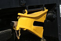


_Miyazu_line_engine_running_track.jpg)


