
Community hub
Recent from talks
Contribute something
Nothing was collected or created yet.
Optical telegraph
View on Wikipedia


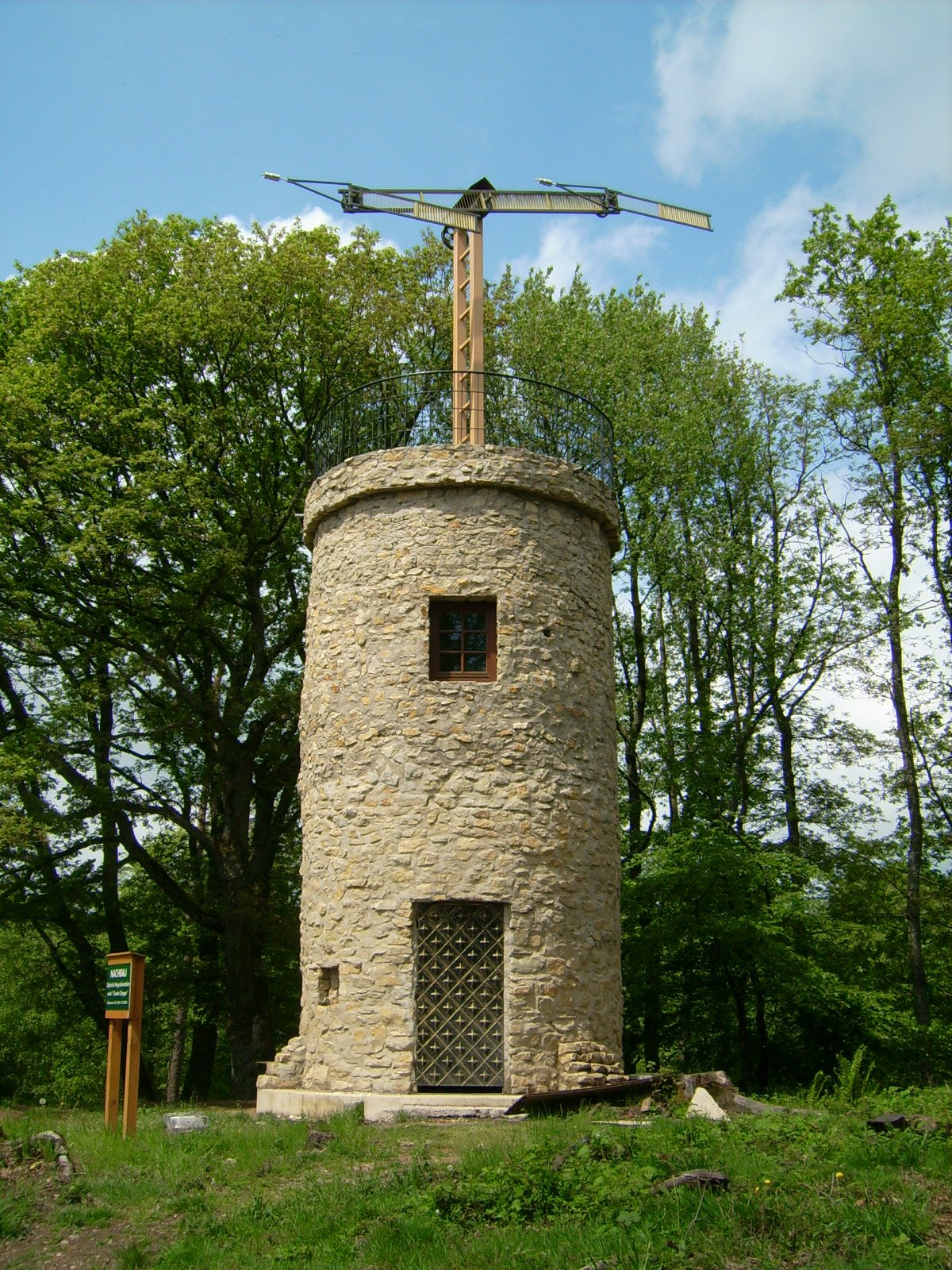
An optical telegraph is a line of stations, typically towers, for the purpose of conveying textual information by means of visual signals (a form of optical communication). There are two main types of such systems: the semaphore telegraph which uses pivoted indicator arms and conveys information according to the direction the indicators point, and the shutter telegraph which uses panels that can be rotated to block or pass the light from the sky behind to convey information.
The most widely used system was the Chappe telegraph, which was invented in France in 1792 by Claude Chappe. It was popular in the late eighteenth to early nineteenth centuries.[1][2][3] Chappe used the term télégraphe to describe the mechanism he had invented – that is the origin of the English word "telegraph".[4] Lines of relay towers with a semaphore rig at the top were built within line of sight of each other, at separations of 5–20 miles (8–32 km). Operators at each tower would watch the neighboring tower through a telescope, and when the semaphore arms began to move spelling out a message, they would pass the message on to the next tower.
This system was much faster than post riders for conveying a message over long distances, and also had cheaper long-term operating costs, once constructed. Half a century later, semaphore lines were replaced by the electrical telegraph, which was cheaper, faster, and more private. The line-of-sight distance between relay stations was limited by geography and weather, and prevented the optical telegraph from crossing wide expanses of water, unless a convenient island could be used for a relay station. A modern derivative of the semaphore system is flag semaphore, signalling with hand-held flags.
Etymology and terminology
[edit]The word semaphore was coined in 1801 by the French inventor of the semaphore line itself, Claude Chappe.[5] He composed it from the Greek elements σῆμα (sêma, "sign"); and from φορός (phorós, "carrying"),[6] or φορά (phorá, "a carrying") from φέρειν (phérein, "to bear").[7] Chappe also coined the word tachygraph, meaning "fast writer".[8] However, the French Army preferred to call Chappe's semaphore system the telegraph, meaning "far writer", which was coined by French statesman André François Miot de Mélito.[9][10][4]
The word semaphoric was first printed in English in 1808: "The newly constructed Semaphoric telegraphs (...) have been blown up", in a news report in the Naval Chronicle.[11] The first use of the word semaphore in reference to English use was in 1816: "The improved Semaphore has been erected on the top of the Admiralty",[12][13] referring to the installation of a simpler telegraph invented by Sir Home Popham.[citation needed] Semaphore telegraphs are also called, "Chappe telegraphs" or "Napoleonic semaphore".[14][15]
Early designs
[edit]
Optical telegraphy dates from ancient times, in the form of hydraulic telegraphs, torches (as used by ancient cultures since the discovery of fire) and smoke signals. Modern designs of semaphores developed via several paths, often simultaneously.
Possibly the earliest was by the British polymath Robert Hooke, who gave a vivid and comprehensive outline of visual telegraphy to the Royal Society in a 1684 submission in which he outlined many practical details. The system (which was motivated by military concerns, following the Battle of Vienna in 1683) was never put into practice.[16][17]

One of the first experiments of optical signalling was carried out by the Anglo-Irish landowner and inventor, Sir Richard Lovell Edgeworth in 1767.[18] He placed a bet with his friend, the horse racing gambler Lord March, that he could transmit knowledge of the outcome of the race in just one hour. Using a network of signalling sections erected on high ground, the signal would be observed from one station to the next by means of a telescope.[19] The signal itself consisted of a large pointer that could be placed into eight possible positions in 45 degree increments. A series of two such signals gave a total 64 code elements and a third signal took it up to 512. He returned to his idea in 1795, after hearing of Chappe's system.
While Edgeworth was developing his design, William Playfair, a Scottish political economist traveling in Europe in 1794, surreptitiously obtained the design and alphabet of the French system from a fleeing royalist. Playfair, who had numerous connections to British officials, provided a model of the system to the Duke of York, commander of British forces, then based in Flanders, and, according to the Encyclopædia Britannica, "hence the alphabet and plan of the machine came to England."[20][21]
Prevalence
[edit]France
[edit]
Credit for the first successful optical telegraph goes to the French engineer Claude Chappe and his brothers in 1792, who succeeded in covering France with a network of 556 stations stretching a total distance of 4,800 kilometres (3,000 mi). Le système Chappe was used for military and national communications until the 1850s.
Development in France
[edit]During 1790–1795, at the height of the French Revolution, France needed a swift and reliable military communications system to thwart the war efforts of its enemies. France was surrounded by the forces of Britain, the Netherlands, Prussia, Austria, and Spain, the cities of Marseille and Lyon were in revolt, and the British Fleet held Toulon. The only advantage France held was the lack of cooperation between the allied forces due to their inadequate lines of communication.
In mid-1790, the Chappe brothers set about devising a system of communication that would allow the central government to receive intelligence and to transmit orders in the shortest possible time. Chappe considered many possible methods including audio and smoke. He even considered using electricity, but could not find insulation for the conductors that would withstand the high-voltage electrostatic sources available at the time.[22][23]
Chappe settled on an optical system and the first public demonstration occurred on 2 March 1791 between Brûlon and Parcé, a distance of 16 kilometres (9.9 mi). The system consisted of a modified pendulum clock at each end with dials marked with ten numerals. The hands of the clocks almost certainly moved much faster than a normal clock. The hands of both clocks were set in motion at the same time with a synchronisation signal. Further signals indicated the time at which the dial should be read. The numbers sent were then looked up in a codebook. In their preliminary experiments over a shorter distance, the Chappes had banged a pan for synchronisation. In the demonstration, they used black and white panels observed with a telescope. The message to be sent was chosen by town officials at Brûlon and sent by René Chappe to Claude Chappe at Parcé who had no pre-knowledge of the message. The message read "si vous réussissez, vous serez bientôt couverts de gloire" (If you succeed, you will soon bask in glory). It was only later that Chappe realised that he could dispense with the clocks and the synchronisation system itself could be used to pass messages.[24]
The Chappes carried out experiments during the next two years, and on two occasions their apparatus at Place de l'Étoile, Paris was destroyed by mobs who thought they were communicating with royalist forces. Their cause was assisted by Ignace Chappe being elected to the Legislative Assembly. In the summer of 1792 Claude was appointed Ingénieur-Télégraphiste and charged with establishing a line of stations between Paris and Lille, a distance of 230 kilometres (140 mi). It was used to carry dispatches for the war between France and Austria. In 1794, it brought news of a French capture of Condé-sur-l'Escaut from the Austrians less than an hour after it occurred.[25] The first symbol of a message to Lille would pass through 15 stations in only nine minutes. The speed of the line varied with the weather, but the line to Lille typically transferred 36 symbols, a complete message, in about 32 minutes. Another line of 50 stations was completed in 1798, covering 488 kilometres (303 mi) between Paris and Strasbourg.[26] From 1803 on, the French also used the 3-arm Depillon semaphore at coastal locations to provide warning of British incursions.[1]
English military engineer William Congreve observed that at the Battle of Vervik of 1793 French commanders directed their forces by using the sails of a prominent local windmill as an improvised signal station. Two of the four sails of the mill had been removed to resemble the arm of the new telegraph.[27][28]
Chappe system technical operation
[edit]The Chappe brothers determined by experiment that it was easier to see the angle of a rod than to see the presence or absence of a panel. Their semaphore was composed of two black movable wooden arms, connected by a cross bar; the positions of all three of these components together indicated an alphabetic letter. With counterweights (named forks) on the arms, the Chappe system was controlled by only two handles and was mechanically simple and reasonably robust. Each of the two 2-metre-long arms could display seven positions, and the 4.6-metre-long cross bar connecting the two arms could display four different angles, for a total of 196 symbols (7×7×4). Night operation with lamps on the arms was unsuccessful.[29] To speed up transmission and to provide some semblance of security, a code book was developed for use with semaphore lines. The Chappes' corporation used a code that took 92 of the basic symbols two at a time to yield 8,464 coded words and phrases.
The revised Chappe system of 1795 provided not only a set of codes but also an operational protocol intended to maximize line throughput. Symbols were transmitted in cycles of "2 steps and 3 movements."
- Step 1, movement 1 (setup): The operator turned the indicator arms to align with the cross bar, forming a non-symbol, and then turned the cross bar into position for the next symbol.
- Step 1, movement 2 (transmission): The operator positioned the indicator arms for current symbol and waited for the downline station to copy it.
- Step 2, movement 3 (completion): The operator turned the cross bar to a vertical or horizontal position, indicating the end of a cycle.
In this manner, each symbol could propagate down the line as quickly as operators could successfully copy it, with acknowledgement and flow control built into the protocol. A symbol sent from Paris took 2 minutes to reach Lille through 22 stations and 9 minutes to reach Lyon through 50 stations. A rate of 2–3 symbols per minute was typical, with the higher figure being prone to errors. This corresponds to only 0.4–0.6 wpm, but with messages limited to those contained in the code book, this could be dramatically increased.[30][31] An additional benefit is that, if the code is kept secret, the content of transmitted messages can be concealed from both onlookers and system operators, even if they are aware that a message is being transmitted. This has remained an important feature of encrypted communications even as the technology for transmitting data has evolved.[32]
History in France
[edit]
After Chappe's initial line (between Paris and Lille), the Paris to Strasbourg with 50 stations followed soon after (1798). Napoleon Bonaparte made full use of the telegraph by obtaining speedy information on enemy movements. In 1801 he had Abraham Chappe build an extra-large station to transmit across the English Channel in preparation for an invasion of Britain. A pair of such stations were built on a test line over a comparable distance. The line to Calais was extended to Boulogne in anticipation and a new design station was briefly in operation at Boulogne, but the invasion never happened. In 1812, Napoleon took up another design of Abraham Chappe for a mobile telegraph that could be taken with him on campaign. This was still in use in 1853 during the Crimean War.[33]
The invention of the telegraph was followed by an enthusiasm concerning its potential to support direct democracy. For instance, based on Rousseau's argument that direct democracy was improbable in large constituencies, the French Intellectual Alexandre-Théophile Vandermonde commented:
Something has been said about the telegraph which appears perfectly right to me and gives the right measure of its importance. Such invention might be enough to render democracy possible in its largest scale. Many respectable men, among them Jean-Jacques Rousseau, have thought that democracy was impossible within large constituencies.… The invention of the telegraph is a novelty that Rousseau did not expect to happen. It enables long-distance communication at the same pace and clarity than that of conversation in a living room. This solution may address by itself the objections to large [direct] democratic republics. It may even be done in the absence of representative constitutions.[34]
The operational costs of the telegraph in the year 1799/1800 were 434,000 francs ($1.2 million in 2015 in silver costs[35]). In December 1800, Napoleon cut the budget of the telegraph system by 150,000 francs ($400,000 in 2015)[35] leading to the Paris-Lyons line being temporarily closed. Chappe sought commercial uses of the system to make up the deficit, including use by industry, the financial sector, and newspapers. Only one proposal was immediately approved—the transmission of results from the state-run lottery. No non-government uses were approved. The lottery had been abused for years by fraudsters who knew the results, selling tickets in provincial towns after the announcement in Paris, but before the news had reached those towns.[36]

In 1819 Norwich Duff, a young British Naval officer, visiting Clermont-en-Argonne, walked up to the telegraph station there and engaged the signalman in conversation. Here is his note of the man's information:[37]
The pay is twenty five sous per day and he [the signalman] is obliged to be there from day light till dark, at present from half past three till half past eight; there are only two of them and for every minute a signal is left without being answered they pay five sous: this is a part of the branch which communicates with Strasburg and a message arrives there from Paris in six minutes it is here in four.[38]
— Norwich Duff
The network was reserved for government use, but an early case of wire fraud occurred in 1834 when two bankers, François and Joseph Blanc, bribed the operators at a station near Tours on the line between Paris and Bordeaux to pass Paris stock exchange information to an accomplice in Bordeaux. It took three days for the information to travel the 480-kilometre (300 mi) distance, giving the schemers plenty of time to play the market. An accomplice at Paris would know whether the market was going up or down days before the information arrived in Bordeaux via the newspapers, after which Bordeaux was sure to follow. The message could not be inserted in the telegraph directly because it would have been detected. Instead, pre-arranged deliberate errors were introduced into existing messages which were visible to an observer at Bordeaux. Tours was chosen because it was a division station where messages were purged of errors by an inspector who was privy to the secret code used and unknown to the ordinary operators. The scheme would not work if the errors were inserted prior to Tours. The operators were told whether the market was going up or down by the colour of packages (either white or grey paper wrapping) sent by mail coach, or, according to another anecdote, if the wife of the Tours operator received a package of socks (down) or gloves (up) thus avoiding any evidence of misdeed being put in writing.[39] The scheme operated for two years until it was discovered in 1836.[40][41]
The French optical system remained in use for many years after other countries had switched to the electrical telegraph. Partly, this was due to inertia; France had the most extensive optical system and hence the most difficult to replace. But there were also arguments put forward for the superiority of the optical system. One of these was that the optical system is not so vulnerable to saboteurs as an electrical system with many miles of unguarded wire. Samuel Morse failed to sell the electrical telegraph to the French government. Eventually the advantages of the electrical telegraph of improved privacy, and all-weather and nighttime operation won out.[42] A decision was made in 1846 to replace the optical telegraph with the Foy–Breguet electrical telegraph after a successful trial on the Rouen line. This system had a display which mimicked the look of the Chappe telegraph indicators to make it familiar to telegraph operators. Jules Guyot issued a dire warning of the consequences of what he considered to be a serious mistake. It took almost a decade before the optical telegraph was completely decommissioned. One of the last messages sent over the French semaphore was the report of the fall of Sebastopol in 1855.[43]
Sweden
[edit]
Sweden was the second country in the world, after France, to introduce an optical telegraph network.[44] Its network became the second most extensive after France.[45] The central station of the network was at the Katarina Church in Stockholm.[46] The system was faster than the French system, partly due to the Swedish control panel[47] and partly to the ease of transcribing the octal code (the French system was recorded as pictograms).[48] The system was used primarily for reporting the arrival of ships, but was also useful in wartime for observing enemy movements and attacks.[49]
The last stationary semaphore link in regular service was in Sweden, connecting an island with a mainland telegraph line. It went out of service in 1880.
Development in Sweden
[edit]Inspired by news of the Chappe telegraph, the Swedish inventor Abraham Niclas Edelcrantz experimented with the optical telegraph in Sweden. He constructed a three-station experimental line in 1794 running from the royal castle in Stockholm, via Traneberg, to the grounds of Drottningholm Castle, a distance of 12 kilometres (7.5 mi). The first demonstration was on 1 November, when Edelcrantz sent a poem dedicated to the king, Gustav IV Adolf, on his fourteenth birthday. On 7 November the king brought Edelcrantz into his Council of Advisers with a view to building a telegraph throughout Sweden, Denmark, and Finland.[50]
Edelcrantz system technical operation
[edit]After some initial experiments with Chappe-style indicator arms, Edelcrantz settled on a design with ten iron shutters. Nine of these represented a 3-digit octal number and the tenth, when closed, meant the code number should be preceded by "A". This gave 1,024 codepoints which were decoded to letters, words or phrases via a codebook.[51] The telegraph had a sophisticated control panel which allowed the next symbol to be prepared while waiting for the previous symbol to be repeated on the next station down the line. The control panel was connected by strings to the shutters. When ready to transmit, all the shutters were set at the same time with the press of a footpedal.[47]
The shutters were painted matte black to avoid reflection from sunlight and the frame and arms supporting the shutters were painted white or red for best contrast.[52] Around 1809 Edelcrantz introduced an updated design. The frame around the shutters was dispensed with leaving a simpler, more visible, structure of just the arms with the indicator panels on the end of them. The "A" shutter was reduced to the same size as the other shutters and offset to one side to indicate which side was the most significant digit (whether the codepoint is read left-to-right or right-to-left is different for the two adjacent stations depending on which side they are on).[49] This was previously indicated with a stationary indicator fixed to the side of the frame, but without a frame this was no longer possible.[53]
The distance that a station could transmit depended on the size of the shutters and the power of the telescope being used to observe them. The smallest object visible to the human eye is one that subtends an angle of 40 seconds of arc, but Edelcrantz used a figure of 4 minutes of arc to account for atmospheric disturbances and imperfections of the telescope. On that basis, and with a 32× telescope, Edelcrantz specified shutter sizes ranging from 23 centimetres (9 in) for a distance of half a Swedish mile (5.3 km; 3+1⁄4 mi) to 140 centimetres (54 in) for 3 Swedish miles (32 km; 20 mi).[54] These figures were for the original design with square shutters. The open design of 1809 had long oblong shutters which Edelcrantz thought was more visible.[55] Distances much further than these would require impractically high towers to overcome the curvature of the Earth as well as large shutters. Edelcrantz kept the distance between stations under 2 Swedish miles (21 km; 13 mi) except where large bodies of water made it unavoidable.[56]
The Swedish telegraph was capable of being used at night with lamps. On smaller stations lamps were placed behind the shutters so that they became visible when the shutter was opened. For larger stations, this was impractical. Instead, a separate tin box matrix with glass windows was installed below the daytime shutters. The lamps inside the tin box could be uncovered by pulling strings in the same way the daytime shutters were operated. Windows on both sides of the box allowed the lamps to be seen by both the upstream and downstream adjacent stations. The codepoints used at night were the complements of the codepoints used during the day. This made the pattern of lamps in open shutters at night the same as the pattern of closed shutters in daytime.[57]
First network: 1795–1809
[edit]The first operational line, Stockholm to Vaxholm, went into service in January 1795. By 1797 there were also lines from Stockholm to Fredriksborg, and Grisslehamn via Signilsskär to Eckerö in Åland. A short line near Gothenburg to Marstrand on the west coast was installed in 1799. During the War of the Second Coalition, Britain tried to enforce a blockade against France. Concerned at the effect on their own trade, Sweden joined the Second League of Armed Neutrality in 1800. Britain was expected to respond with an attack on one of the Nordic countries in the league. To help guard against such an attack, the king ordered a telegraph link joining the systems of Sweden and Denmark. This was the first international telegraph connection in the world. Edelcrantz made this link between Helsingborg in Sweden and Helsingør in Denmark, across the Öresund, the narrow strait separating the two countries. A new line along the coast from Kullaberg to Malmö, incorporating the Helsingborg link, was planned in support and to provide signalling points to the Swedish fleet. Nelson's attack on the Danish fleet at Copenhagen in 1801 was reported over this link, but after Sweden failed to come to Denmark's aid it was not used again and only one station on the supporting line was ever built.[58]
In 1808 the Royal Telegraph Institution was created and Edelcrantz was made director.[59] The Telegraph Institution was put under the jurisdiction of the military, initially as part of the Royal Engineering Corps.[60] A new code was introduced to replace the 1796 codebook with 5,120 possible codepoints with many new messages. The new codes included punishments for delinquent operators. These included an order to the operator to stand on one of the telegraph arms (code 001-721), and a message asking an adjacent station to confirm that they could see him do it (code 001-723).[61] By 1809, the network had 50 stations over 200 km (120 mi) of line employing 172 people.[49] In comparison, the French system in 1823 had 650 km (400 mi) of line and employed over three thousand people.[44]
In 1808, the Finnish War broke out when Russia seized Finland, then part of Sweden. Åland was attacked by Russia and the telegraph stations destroyed. The Russians were expelled in a revolt, but attacked again in 1809. The station at Signilsskär found itself behind enemy lines, but continued to signal the position of Russian troops to the retreating Swedes. After Sweden ceded Finland in the Treaty of Fredrikshamn, the east coast telegraph stations were considered superfluous and put into storage. In 1810, the plans for a south coast line were revived but were scrapped in 1811 due to financial considerations. Also in 1811, a new line from Stockholm via Arholma to Söderarm lighthouse was proposed, but also never materialised.[62] For a while, the telegraph network in Sweden was almost non-existent, with only four telegraphists employed by 1810.[63]
Rebuilding the network
[edit]The post of Telegraph Inspector was created as early as 1811, but the telegraph in Sweden remained dormant until 1827 when new proposals were put forward. In 1834, the Telegraph Institution was moved to the Topographical Corps. The Corps head, Carl Fredrik Akrell, conducted comparisons of the Swedish shutter telegraph with more recent systems from other countries. Of particular interest was the semaphore system of Charles Pasley in England which had been on trial in Karlskrona. Tests were performed between Karlskrona and Drottningskär, and, in 1835, nighttime tests between Stockholm and Fredriksborg. Akrell concluded that the shutter telegraph was faster and easier to use, and was again adopted for fixed stations. However, Pasley's semaphore was cheaper and easier to construct, so was adopted for mobile stations. By 1836 the Swedish telegraph network had been fully restored.[60]
The network continued to expand. In 1837, the line to Vaxholm was extended to Furusund. In 1838 the Stockholm-Dalarö-Sandhamn line was extended to Landsort. The last addition came in 1854 when the Furusund line was extended to Arholma and Söderarm.[60] The conversion to electrical telegraphy was slower and more difficult than in other countries. The many stretches of open ocean needing to be crossed on the Swedish archipelagos was a major obstacle. Akrell also raised similar concerns to those in France concerning potential sabotage and vandalism of electrical lines. Akrell first proposed an experimental electrical telegraph line in 1852. For many years the network consisted of a mix of optical and electrical lines. The last optical stations were not taken out of service until 1881,[64] the last in operation in Europe. In some places, the heliograph replaced the optical telegraph rather than the electrical telegraph.[65]}
United Kingdom
[edit]
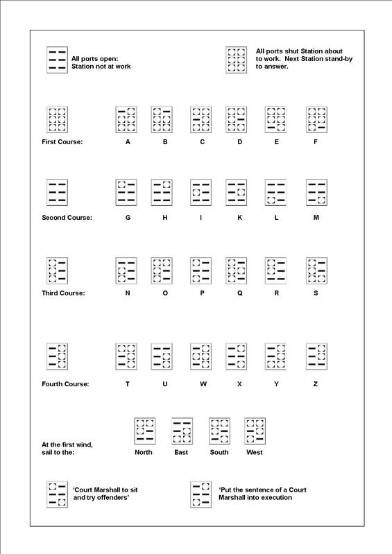
In Ireland, Richard Lovell Edgeworth returned to his earlier work in 1794, and proposed a telegraph there to warn against an anticipated French invasion; however, the proposal was not implemented. Lord George Murray, stimulated by reports of the Chappe semaphore, proposed a system of visual telegraphy to the British Admiralty in 1795.[3] He employed rectangular framework towers with six five-foot-high octagonal shutters on horizontal axes that flipped between horizontal and vertical positions to signal.[66] The Rev. Mr Gamble also proposed two distinct five-element systems in 1795: one using five shutters, and one using five ten-foot poles.[3] The British Admiralty accepted Murray's system in September 1795, and the first system was the 15 site chain from London to Deal.[67] Messages passed from London to Deal in about sixty seconds, and sixty-five sites were in use by 1808.[67]

Chains of Murray's shutter telegraph stations were built along the following routes: London–Deal and Sheerness, London–Great Yarmouth, and London–Portsmouth and Plymouth.[68] The line to Plymouth was not completed until 4 July 1806, and so could not be used to relay the news of Trafalgar.[69] The shutter stations were temporary wooden huts, and at the conclusion of the Napoleonic wars they were no longer necessary, and were closed down by the Admiralty in March 1816.[70]
Following the Battle of Trafalgar, the news was transmitted to London by frigate to Falmouth, from where the captain took the dispatches to London by coach along what became known as the Trafalgar Way; the journey took 38 hours. This delay prompted the Admiralty to investigate further.
A replacement telegraph system was sought, and of the many ideas and devices put forward the Admiralty chose the simpler semaphore system invented by Sir Home Popham.[2][3] A Popham semaphore was a single fixed vertical 30 foot pole, with two movable 8 foot arms attached to the pole by horizontal pivots at their ends, one arm at the top of the pole, and the other arm at the middle of the pole.[1][2] The signals of the Popham semaphore were found to be much more visible than those of the Murray shutter telegraph.[1] Popham's 2-arm semaphore was modelled after the 3-arm Depillon French semaphore.[1] An experimental semaphore line between the Admiralty and Chatham was installed in July 1816, and its success helped to confirm the choice.[70]
Subsequently, the Admiralty decided to establish a permanent link to Portsmouth and built a chain of semaphore stations. Work started in December 1820[70] with Popham's equipment replaced with another two-arm system invented by Charles Pasley. Each of the arms of Pasley's system could take on one of eight positions and it thus had more codepoints than Popham's.[71] In good conditions messages were sent from London to Portsmouth in less than eight minutes.[72] The line was operational from 1822 until 1847, when the railway and electric telegraph provided a better means of communication. The semaphore line did not use the same locations as the shutter chain, but followed almost the same route with 15 stations: Admiralty (London), Chelsea Royal Hospital, Putney Heath, Coombe Warren, Coopers Hill, Chatley Heath, Pewley Hill, Bannicle Hill, Haste Hill (Haslemere), Holder Hill, (Midhurst), Beacon Hill, Compton Down, Camp Down, Lumps Fort (Southsea), and Portsmouth Dockyard. The semaphore tower at Chatley Heath, which replaced the Netley Heath station of the shutter telegraph, is currently being restored by the Landmark Trust as self-catering holiday accommodation.[73] There will be public access on certain days when the restoration is complete.[74]
The Board of the Port of Liverpool obtained a local act of Parliament, the Liverpool Improvement Act 1825 (6 Geo. 4. c. clxxxvii), to construct a chain of Popham optical semaphore stations from Liverpool to Holyhead in 1825.[75] The system was designed and part-owned by Barnard L. Watson, a reserve marine officer, and came into service in 1827. The line is possibly the only example of an optical telegraph built entirely for commercial purposes. It was used so that observers at Holyhead could report incoming ships to the Port of Liverpool and trading could begin in the cargo being carried before the ship docked. The line was kept in operation until 1860 when a railway line and associated electrical telegraph made it redundant.[76][77]: 181–183 Many of the prominences on which the towers were built ('telegraph hills') are known as Telegraph Hill to this day.
British empire
[edit]Ireland
[edit]In Ireland R.L. Edgeworth was to develop an optical telegraph based on a triangle pointer, measuring up to 16 feet in height. Following several years promoting his system, he was to get admiralty approval and engaged in its construction during 1803–1804. The completed system ran from Dublin to Galway and was to act as a rapid warning system in case of French invasion of the west coast of Ireland. Despite its success in operation, the receding threat of French invasion was to see the system disestablished in 1804.[78]
Canada
[edit]In Canada, Prince Edward, Duke of Kent established the first semaphore line in North America. In operation by 1800, it ran between the city of Halifax and the town of Annapolis in Nova Scotia, and across the Bay of Fundy to Saint John and Fredericton in New Brunswick. In addition to providing information on approaching ships, the Duke used the system to relay military commands, especially as they related to troop discipline. The Duke had envisioned the line reaching as far as the British garrison at Quebec City, but the many hills and coastal fog meant the towers needed to be placed relatively close together to ensure visibility. The labour needed to build and continually man so many stations taxed the already stretched-thin British military and there is doubt the New Brunswick line was ever in operation. With the exception of the towers around Halifax harbour, the system was abandoned shortly after the Duke's departure in August 1800.[79][80]
Malta
[edit]
The British military authorities began to consider installing a semaphore line in Malta in the early 1840s. Initially, it was planned that semaphore stations be established on the bell towers and domes of the island's churches, but the religious authorities rejected the proposal. Due to this, in 1848 new semaphore towers were constructed at Għargħur and Għaxaq on the main island, and another was built at Ta' Kenuna on Gozo. Further stations were established at the Governor's Palace, Selmun Palace and the Giordan Lighthouse. Each station was staffed by the Royal Engineers.[81]
India
[edit]
In India, semaphore towers were introduced in 1810. A series of towers were built between Fort William, Kolkata to Chunar Fort near Varanasi.The towers in the plains were 75–80 ft (23–24 m) tall and those in the hills were 40–50 ft (12–15 m) tall, and were built at an interval of about 13 km (8 mi).[82]
Van Diemen's Land
[edit]In southern Van Diemens Land (Tasmania) a signalling system to announce the arrival of ships was suggested by Governor-In-Chief Lachlan Macquarie when he made his first visit in 1811 [83] Initially a simple flag system in 1818 between Mt. Nelson and Hobart, it developed into a system with two revolving arms by 1829, the system was quite crude and the arms were difficult to operate. In 1833 Charles O'Hara Booth took over command of the Port Arthur penal settlement, as an "enthusiast in the art of signalling" [84] he saw the value of better communications with the headquarters in Hobart. During his command the semaphore system was extended to include 19 stations on the various mountains and islands between Port Arthur and Hobart. Until 1837 three single rotating arm semaphores were used. Subsequently the network was upgraded to use signal posts with six arms - a pair top, middle and bottom. This enabled the semaphore to send 999 signal codes. Captain George King of the Port Office and Booth together contributed to the code book for the system.[85] King drew up shipping related codes and Booth added Government, Military and penal station matters. In 1877 Port Arthur was closed and the semaphore was operated for shipping signals only, it was finally replaced with a simple flagstaff after the introduction of the telephone in 1880.

In the north of the state there was a requirement to report on shipping arrivals as they entered the Tamar Estuary, some 56 kilometres (35 mi) from the main port at this time in Launceston. The Tamar Valley Semaphore System was based on a design by Peter Archer Mulgrave.[86] This design used two arms, one with a cross piece at the end. The arms were rotated by ropes, and later chains. The barred arm positions indicated numbers 1 to 6 clockwise from the bottom left and the unbarred arm 7,8,9, STOP and REPEAT.

A message was sent by sending numbers sequentially to make up a code. As with other systems the code was decoded via a code book. On 1 October 1835 it was announced in the Launceston Advertiser - "...that the signal stations are now complete from Launceston to George Town, and communication may he made, as well as received, from the Windmill Hill to George Town, in a very few minutes, on a clear day".[87] The system comprised six stations - Launceston Port Office, Windmill Hill, Mt. Direction, Mt.George, George Town Port Office, Low Head lighthouse. The Tamar Valley semaphore telegraph operated for twenty-two and a half years closing on 31 March 1858 after the introduction of the electric telegraph.[88]
In the 1990s the Tamar Valley Signal Station Committee Inc. was formed to restore the system. The works were carried out over several years and the semaphore telegraph was declared complete once more on Sunday 30 September 2001.[89]
Iberia
[edit]
Spain
[edit]In Spain, the engineer Agustín de Betancourt developed his own system which was adopted by that state; in 1798 he received a Royal Appointment,[90] and the first stretch of line connecting Madrid and Aranjuez was in operation as of August 1800.[91] Spain was spanned by an extensive semaphore telegraph network in the 1840s and 1850s.[92] The three main semaphore lines radiated from Madrid.[92][93] The first ran north to Irun on the Atlantic coast at the French border. The second ran east to the Mediterranean, then north along the coast through Barcelona to the French border. The third ran south to Cadiz on the Atlantic coast. These lines served many other Spanish cities, including: Aranjuez, Badajoz, Burgos, Castellon, Ciudad Real, Córdoba, Cuenca, Gerona, Pamplona, San Sebastian, Seville, Tarancon, Tarragona, Toledo, Valladolid, Valencia, Vitoria and Zaragoza.[93]
The rugged topography of the Iberian peninsula that facilitated the design of semaphore lines conveying information from hilltop to hilltop, made it difficult to implement wire telegraph lines when that technology was introduced in the mid 19th century. The Madrid-Cadiz line was the first to be dismantled in 1855, but other segments of the optical system continued to function until the end of the Carlist Wars in 1876.[94]
Portugal
[edit]In Portugal, the British forces fighting Napoleon in Portugal soon found that the Portuguese Army had already a very capable semaphore terrestrial system working since 1808, giving the Duke of Wellington a decisive advantage in intelligence. The innovative Portuguese telegraphs, designed by Francisco António Ciera, a mathematician, were of 3 types: 3 shutters, 3 balls and 1 pointer/moveable arm.[95] He also wrote the code book "Táboas Telegráphicas", the same for the 3 telegraph types. Since early 1810 the network was operated by "Corpo Telegráfico", the first Portuguese military Signal Corps.[96]
Other regions
[edit]
Once it had proved its success in France, the optical telegraph was imitated in many other countries, especially after it was used by Napoleon to coordinate his empire and army. In most of these countries, the postal authorities operated the semaphore lines. Many national services adopted signalling systems different from the Chappe system. For example, the UK and Sweden adopted systems of shuttered panels (in contradiction to the Chappe brothers' contention that angled rods are more visible). In some cases, new systems were adopted because they were thought to be improvements. But many countries pursued their own, often inferior, designs for reasons of national pride or not wanting to copy from rivals and enemies.[97]
In 1801, the Danish post office installed a semaphore line across the Great Belt strait, Storebæltstelegrafen, between islands Funen and Zealand with stations at Nyborg on Funen, on the small island Sprogø in the middle of the strait, and at Korsør on Zealand. It was in use until 1865.[98]

In the Kingdom of Prussia, Frederick William III ordered the construction of an experimental line in 1819, but due to opposition from the defence minister Karl von Hake, nothing happened until 1830 when a short three-station line between Berlin and Potsdam was built. The design was based on the Swedish telegraph with the number of shutters increased to twelve.[99] Postrat Carl Pistor proposed instead a semaphore system based on Watson's design in England. An operational line of this design running Berlin-Magdeburg-Dortmund-Köln-Bonn-Koblenz was completed in 1833. The line employed about 200 people, comparable to Sweden, but no network ever developed and no more official lines were built. The line was decommissioned in 1849 in favour of an electrical line.[100]
Although there were no more government sponsored official lines, there was some private enterprise. Johann Ludwig Schmidt opened a commercial line from Hamburg to Cuxhaven in 1837. In 1847, Schmidt opened a second line from Bremen to Bremerhaven. These lines were used for reporting the arrival of commercial ships. The two lines were later linked with three additional stations to create possibly the only private telegraph network in the optical telegraph era.[101] The telegraph inspector for this network was Friedrich Clemens Gerke, who would later move to the Hamburg-Cuxhaven electrical telegraph line and develop what became the International Morse Code.[102] The Hamburg line went out of use in 1850, and the Bremen line in 1852.[103]
In Russia, Tsar Nicolas I inaugurated a line between Moscow and Warsaw of 1,200 kilometres (750 mi) length in 1833; it needed 220 stations staffed by 1,320 operators. The stations were noted to be unused and decaying in 1859, so the line was probably abandoned long before this.[48]
In the United States, the first optical telegraph was built by Jonathan Grout in 1804 but ceased operation in 1807. This 104-kilometre (65 mi) line between Martha's Vineyard with Boston transmitted shipping news. An optical telegraph system linking Philadelphia and the mouth of the Delaware Bay was in place by 1809 and had a similar purpose; a second line to New York City was operational by 1834, when its Philadelphia terminus was moved to the tower of the Merchants Exchange. One of the principal hills in San Francisco, California is also named "Telegraph Hill", after the semaphore telegraph which was established there in 1849 to signal the arrival of ships into San Francisco Bay.
The telegraph was introduced to the United States Navy by David Porter, upon returning from Europe. He suggested that the US Navy build a telegraphic system "similar to those ... in Europe." (The United States Secretary of the Navy, Robert Smith, was also intrigued by the concept.) Smith replied on 4 June, granting approval of Porter's idea, advising him that the Navy would dispatch him 20 telescopes. In Europe, there was typically a distance between the telegraph stations of 10 to 16 kilometres (6 to 10 mi). Owing to the twisting of the Mississippi, and the dense forests along its banks, the stations were 5 to 6 kilometres (3 to 4 mi) apart. On 3 February 1809, Porter reported that twelve stations had been built, extending 72 kilometres (45 mi) below New Orleans, halfway to the start of the river delta. These shorter distances meant that the operating costs were greater than for the equivalent networks in Europe.[104] The Secretary of the Navy stopped further construction on the grounds of excessive cost. Had the network been extended to the end of the river, it would have been possible to send or receive a message from the Balize in five minutes.[105] Secretary Smith had intended for the materials to be installed in gunboats for experimental trials. In a subsequent communication in October 1808, he told Porter that this project could not proceed any further without congressional authorization and funding.[104]
In January 1812, the President approached the Secretary of the Navy, wishing to explore telegraphy between New York, Washington and other locations, and how this could be done. "A telegraphic communication between Sandy Hook & the Narrows, thence to the City, is immediately desirable," as well as estimates to cost. A prudent response commented on how dense forests made it impractical to implement for long distances. In contrast, the proposed 39-kilometre (24 mi) network between Sandy Hook and New York could be created at a cost of $500, exclusive of staffing.[104] This was approved, and Isaac Chauncey, as commandant of the New York Naval Shipyard was asked to commence its construction. He was hindered by disapproval from some of the affected property owners. The telegraph network operations began about 1 July. Despite an apparent interest in telegraphy from a number of key decision-makers, the New York–Sandy Hook line was the only active system the Navy had in operation during the War of 1812.[104]
As first data networks
[edit]The optical telegraphs put in place at the turn of the 18th/19th centuries were the first examples of data networks.[106] Chappe and Edelcrantz independently invented many features that are now commonplace in modern networks, but were then revolutionary and essential to the smooth running of the systems. These features included control characters, routing, error control, flow control, message priority and symbol rate control. Edelcrantz documented the meaning and usage of all his control codes from the start in 1794. The details of the early Chappe system are not known precisely; the first operating instructions to survive date to 1809 and the French system is not as fully explained as the Swedish.[107]
Some of the features of these systems are considered advanced in modern practice and have been recently reinvented. An example of this is the error control codepoint 707 in the Edelcrantz code. This was used to request the repeat of a specified recent symbol. The 707 was followed by two symbols identifying the row and column in the current page of the logbook that it was required to repeat. This is an example of a selective repeat and is more efficient than the simple go back n strategy used on many modern networks.[108] This was a later addition; both Edelcrantz (codepoint 272), and Chappe (codepoint 2H6)[note 1] initially used only a simple "erase last character" for error control, taken directly from Hooke's 1684 proposal.[109]
Routing in the French system was almost permanently fixed; only Paris and the station at the remote end of a line were allowed to initiate a message. The early Swedish system was more flexible, having the ability to set up message connections between arbitrary stations. Similar to modern networks, the initialisation request contained the identification of the requesting and target station. The request was acknowledged by the target station by sending the complement of the code received. This protocol is unique with no modern equivalent.[108] This facility was removed from the codebook in the revision of 1808. After this, only Stockholm would normally initiate messages with other stations waiting to be polled.[108]
The Prussian system required the Coblenz station (at the end of the line) to send a "no news" message (or a real message if there was one pending) back to Berlin on the hour, every hour. Intermediate stations could only pass messages by replacing the "no news" message with their traffic. On arrival in Berlin, the "no news" message was returned to Coblenz with the same procedure. This can be considered an early example of a token passing system. This arrangement required accurate clock synchronisation at all the stations. A synchronisation signal was sent out from Berlin for this purpose every three days.[110]
Another feature that would be considered advanced in a modern electronic system is the dynamic changing of transmission rates. Edelcrantz had codepoints for faster (770) and slower (077). Chappe also had this feature.[111]
In popular culture
[edit]
By the mid-19th century, the optical telegraph was well known enough to be referenced in popular works without special explanation. The Chappe telegraph appeared in contemporary fiction and comic strips. In "Mister Pencil" (1831), a comic strip by Rodolphe Töpffer, a dog fallen on a Chappe telegraph's arm—and its master attempting to help get it down—provoke an international crisis by inadvertently transmitting disturbing messages. In Lucien Leuwen (1834), Stendhal pictures a power struggle between Lucien Leuwen and the prefect M. de Séranville with the telegraph's director M. Lamorte. In Chapter 60 ("The Telegraph") of Alexandre Dumas' The Count of Monte Cristo (1844), the title character describes with fascination the semaphore line's moving arms: "I had at times seen rise at the end of a road, on a hillock and in the bright light of the sun, these black folding arms looking like the legs of an immense beetle."[112] He later bribes a semaphore operator to relay a false message in order to manipulate the French financial market. Dumas also describes in detail the functioning of a Chappe telegraph line. In Hector Malot's novel Romain Kalbris (1869), one of the characters, a girl named Dielette, describes her home in Paris as "...next to a church near which there was a clock tower. On top of the tower there were two large black arms, moving all day this way and that. [I was told later] that this was Saint-Eustache church and that these large black arms were a telegraph."[113]
In the 21st century, the optical telegraph concept is mainly kept alive in popular culture through fiction such as the novel Pavane and Terry Pratchett's "Clacks" in his Discworld novels,[114] most notably the 2004 novel Going Postal.[115]
See also
[edit]- History of telecommunication
- Telegraph code, for more information on many of the codes used
- Optical communication
- Polybius square
- Railway signalling
- San Jose Semaphore
- Semaphore Flag Signaling System
- Signal lamp
- Telegraph Hill, for a list of telegraph hills
- Wigwag, a flag signaling system that also used telescopes and towers
Notes
[edit]- ^ The notation here follows that given in Holzmann & Pehrson (p. 211). The two digits represent, respectively the angle of the left and right indicators. Vertical pointing up is "1" and each successive 45° from this position increments this number. "H" means the regulator is in the horizontal position and "V" the vertical.
References
[edit]- Citations
- ^ a b c d e Burns 2004, Chapter 2: Semaphore Signalling
- ^ a b c "Telegraph". Encyclopædia Britannica. Vol. 10 (6th ed.). 1824. pp. 645–651.
- ^ a b c d David Brewster, ed. (1832). "Telegraph". The Edinburgh Encyclopaedia. Vol. 17. pp. 664–667.
- ^ a b Axon, William (1880). "On the History of the word Telegraph". Proceedings of the Literary and Philosophical Society of Manchester. 19: 183. Retrieved 10 June 2023.
- ^ Groundbreaking Scientific Experiments, Inventions & Discoveries of the 18th Century, Jonathan Shectman, p. 172
- ^ Oxford English Dictionary.
- ^ Webster's Unabridged Dictionary.
- ^ Beyer, Rick, The Greatest Stories Never Told, A&E Television Networks / The History Channel, ISBN 0-06-001401-6, p. 60
- ^ Le Robert historique de la langue française, 1992, 1998
- ^ Miot de Mélito, André (1858). Mémoires du Comte Miot de Melito V.2. Lévy. p. 38. Retrieved 12 October 2024.
- ^ Sherk, Bill (2004). 500 Years of New Words. Toronto: The Dundurn Group. p. 210. ISBN 1-55002-525-2.
- ^ Sherk, Bill (1 September 2004). 500 Years of New Words: the fascinating story of how, when, and why these words first entered the English language. Dundurn. p. 320. ISBN 978-1-4597-1822-7.
- ^ Gater, G. H.; Wheeler, E. P., eds. (1935). "The Admiralty". Survey of London. Vol. 16. London County Council. pp. 45–70 – via British History Online.
- ^ Tour du télégraphe Chappe (in French) Archived 28 September 2011 at the Wayback Machine
- ^ Schofield, Hugh (16 June 2013). "How Napoleon's semaphore telegraph changed the world". BBC News. Retrieved 3 March 2022.
- ^ "The Origin of the Railway Semaphore". Mysite.du.edu. Retrieved 17 June 2013.
- ^ "History of the Telephone part2". Ilt.columbia.edu. Archived from the original on 28 November 2012. Retrieved 17 June 2013.
- ^ Rees, Abraham, ed. (1802–1820). "Telegraph". Cyclopædia. Vol. 35. London: Longman, Hurst, Rees, Orme & Brown. Unpaginated work: pages 9-11 of the article entry.
- ^ Burns 2004.
- ^ Encyclopædia Britannica, Vol. 18 (Edinburgh: Bell and Macfarquhar, 1797) p. 336 https://ia601900.us.archive.org/32/items/1797EncyclopediaBritannicaNLS/Third%20edition%20-%20Encyclopaedia%20Britannica%20Volume%2018%2C%20STR-ZYM.pdf
- ^ The Annual Biography and Obituary (etc.). Longman, Hurst, Rees. 1824.
- ^ Patrice Flichy, Dynamics of Modern Communication, p. 33, SAGE, 1995 ISBN 144622712X
- ^ Holzmann & Pehrson, p. 53
- ^ Holzmann & Pehrson, pp. 53–55
- ^ How Napoleon's semaphore telegraph changed the world, BBC News, Hugh Schofield, 16 June 2013
- ^ "Engineering and Technology History Wiki" (PDF).
- ^ Gamble, John (1797). An essay on the different modes of communication by signals. London: William Miller. p. 66. OCLC 495253065.
- ^ ffoulkes, Charles (1943). "Notes on the Development of Signals Used for Military Purposes". Journal of the Society for Army Historical Research. 22 (85): 20–27. ISSN 0037-9700. JSTOR 44219957.
- ^ Holzmann & Pehrson, p. 213
- ^ Holzmann & Pehrson
- ^ "Les dépêches". chappe.ec-lyon.fr. Archived from the original on 2 February 2014. Retrieved 11 January 2022.
- ^ "How Napoleon's semaphore telegraph changed the world". BBC News. 16 June 2013. Retrieved 8 November 2024.
- ^ Holzmann & Pehrson, pp. 71–73
- ^ Mattelart, Armand (1999). "La communication et la promesse de rédemption". Quaderni. 40 (1): 69–78. doi:10.3406/quad.1999.1428.
- ^ a b Rodney Edvinsson, Historical Currency Converter, accessed 8 January 2021.
- ^
- Shelby T. McCloy, French Inventions of the Eighteenth Century, p. 46, University Press of Kentucky, 2015 ISBN 0813163978.
- Rollo Appleyard, Pioneers of Electrical Communication, pp. 271–272, Books for Libraries Press, 1968 (reprint of Macmillan, 1930) OCLC 682063110.
- ^ Commander Norwich Duff's European Tour Journal, 1819, www.kittybrewster.com, archived 24 June 2007.
- ^ Journal of Norwich Duff, 13 July 1819.
- ^ Berloquin, Pierre (2008). Hidden Codes & Grand Designs. Sterling. p. 25. ISBN 978-1-4027-7300-6.
- ^ Holzmann & Pehrson, pp. 75–76
- ^ Holzmann, Gerard J. (15 September 1999). "Taking stock". Inc.
- ^ Holzmann, Gerard. "Data Communications: The First 2,500 Years" (PDF). Retrieved 28 June 2011.
- ^ Holzmann & Pehrson, pp. 92–94
- ^ a b David Greene, Light and Dark: An Exploration in Science, Nature, Art and Technology, p. 159, CRC Press, 2016 ISBN 1420034030.
- ^ Holzmann & Pehrson, p. x
- ^ Edelcrantz, p. 174
- ^ a b Holzmann & Pehrson, pp. 104–105
- ^ a b Holzmann & Pehrson, p. 180
- ^ a b c Holzmann & Pehrson, p. 117
- ^ Holzmann & Pehrson, pp. 101–103
- ^ Holzmann & Pehrson, p. 103
- ^ Edelcrantz, p. 164
- ^ Edelcrantz, pp. 144, 146
- ^ Edelcrantz, pp. 166–167
- ^ Edelcrantz, p. 165
- ^ Edelcrantz, p. 169
- ^ Edelcrantz, pp. 170–171
- ^ Holzmann & Pehrson, pp. 105–109
- ^ Holzmann & Pehrson, p. 114
- ^ a b c Holzmann & Pehrson, p. 120
- ^ Holzmann & Pehrson, p. 116
- ^ Holzmann & Pehrson, pp. 117–118
- ^ Holzmann & Pehrson, pp. 118, 120
- ^ Greene 2003, p. 159.
- ^ Holzmann & Pehrson, pp. 120–126
- ^ Lieutenant Watson's Telegraph Mechanics' magazine, Volume 8 No. 222, Knight and Lacey, 1828, pages 294-299
- ^ a b F.B. Wrixon (2005), ISBN 978-1-57912-485-4 Codes, Ciphers, Secrets and Cryptic Communication pp. 444-445 cover Murray's shutter telegraph in the U.K., with codes.
- ^ a b "Optical Telegraph".
- ^ Burns 2004, p. 49.
- ^ a b c Military Signals from the South Coast, John Goodwin, 2000
- ^ Holzmann & Pehrson, p. 196
- ^ C. I. Hamilton, The Making of the Modern Admiralty: British Naval Policy-Making, 1805–1927, p. 92, Cambridge University Press, 2011 ISBN 9781139496544.
- ^ "Our plans for Semaphore Tower". Landmark Trust. Archived from the original on 21 March 2020. Retrieved 21 March 2020.
- ^ Curley, Rebecca (20 February 2020). "Chatley Tower restoration to make landmark rentable". Sutton & Croydon Guardian. Newsquest Media Group Ltd. Retrieved 21 March 2020.
- ^ Faster Than The Wind, The Liverpool to Holyhead Telegraph, Frank Large, an avid publication ISBN 0-9521020-9-9
- ^ Holzmann & Pehrson, p. 197
- ^ Seija-Riitta Laakso, Across the Oceans: Development of Overseas Business Information Transmission 1815-1875, BoD - Books on Demand, 2018 ISBN 9517469047
- ^ Adrian James Kirwan, 'R.L. Edgeworth and Optical Telegraphy in Ireland, c. 1790-1805' in Proceedings of the Royal Irish Academy (2017). https://www.jstor.org/stable/10.3318/priac.2017.117.02?seq=1#page_scan_tab_contents
- ^ Raddall, Thomas H. (1971), Warden of the North, Toronto, Canada: McClelland and Stewart Limited[permanent dead link]
- ^ Rens, Jean-Guy (2001), The invisible empire: A history of the telecommunications industry in Canada, Montreal, Canada: McGill-Queen's University Press, ISBN 9780773520523
- ^ "Semaphore Tower". Għargħur Local Council. Archived from the original on 4 March 2016.
- ^ Singh, Gurvinder (18 May 2018). "Towering messengers of a bygone era". No. Business Line. Retrieved 31 March 2019.
- ^ "Maquarie's Journals - Saturday 30th. Novr. 1811". Journeys In Time.
- ^ Masters, W.E. (1973). The Semaphore Telegraph System of Van Diemen's Land. Cat & Fiddle Press. p. 8. ISBN 0-85853-009-0.
- ^ Masters, W.E. (1973). The Semaphore Telegraph System of Van Diemen's Land. Cat & Fiddle Press. p. 14. ISBN 0-85853-009-0.
- ^ "Mulgrave, Peter Archer (1778–1847)". Peter Archer Mulgrave. National Centre of Biography, Australian National University.
{{cite book}}:|website=ignored (help) - ^ "Launceston Advertiser - 1 Oct 1835". Launceston Advertiser. October 1835.
- ^ Shipp, Wayne (2014). The Tamar Valley Semaphore Telegraph. Low Head Pilot Station Museum. p. 37. ISBN 978-0-646-93206-4.
- ^ Shipp, Wayne (2014). The Tamar Valley Semaphore Telegraph. Low Head Pilot Station Museum. p. ix. ISBN 978-0-646-93206-4.
- ^ "Agustín de Betancourt, uno de los ingenieros más prestigiosos de Europa". Museo Postal y Telegráfico (in Spanish). 14 April 2020. Retrieved 18 October 2020.
- ^ "Nostalgia del telégrafo óptico". El País (in Spanish). 4 February 2002. ISSN 1134-6582. Retrieved 18 October 2020.
- ^ a b Roig, Sebastián Olivé (1990). Historia de la telegrafía óptica en España. Madrid: MINISTERIO DE TRANSPORTE, TURISMO Y COMUNICACIONES. Retrieved 10 January 2019.
- ^ a b Fundación Telefónica (2014). Telégrafos. Un relato de su travesía centenaria. Grupo Planeta Spain. ISBN 978-8408129653. Retrieved 10 January 2019.
- ^ Aguilar Pérez, Antonio; y Martínez Lorente, Gaspar, La telegrafía óptica en Cataluña, Scripta Nova, revista electrónica de Geografía y Ciencias Sociales.Vol. VII, núm. 137, 15 de marzo de 2003. Universidad de Barcelona. ISSN 1138-9788.
- ^ Thompson, Mark S. (1 December 2016). "Allied Use of Telegraphs during the Peninsular War" (PDF). Royal Engineers Journal – via The Napoleon Series.
- ^ Luna, Isabel de; Sousa, Ana Catarina; Leal, Rui Sá (2008). "Telegrafia visual na Guerra Peninsular. 1807-1814". Boletim Cultural da Câmara Municipal de Mafra: 67–136.
- ^ Holzmann & Pehrson, pp. 179–180
- ^ The Age of Invention 1849–1920 Archived 2011-07-19 at the Wayback Machine, Post & Tele Museum Danmark, website visited on 8 May 2010.
- ^ Holzmann & Pehrson, pp. 184–185
- ^ Holzmann & Pehrson, pp. 185–187
- ^ Holzmann & Pehrson, p. 186
- ^ Huurdeman, p. 76
- ^ Holzmann & Pehrson, p. 187
- ^ a b c d Martin (2013).
- ^ Sharp (2009).
- ^ Holzmann & Pehrson, p. 214
- ^ Holzmann & Pehrson, pp. 210–216
- ^ a b c Holzmann & Pehrson, p. 216
- ^ Holzmann & Pehrson, pp. 214–215
- ^ Holzmann & Pehrson, p. 188
- ^ Holzmann & Pehrson, pp. 215–216
- ^ Page 84 in LE COMTE DE MONTE-CRISTO Tome III
- ^ See second paragraph in
- ^ Webb, Simon (2019). The Real World of Victorian Steampunk: Steam Planes & Radiophones. Pen and Sword. pp. 49–51. ISBN 978-1526732866.
- ^ Hague, Jim. "The Clacks in Discworld and Roundworld". ACCU.org. ACCU. Retrieved 28 December 2022.
- Bibliography
- Burns, R. W. (2004). Communications: an international history of the formative years. ISBN 978-0-86341-327-8.
- Crowley, David and Heyer, Paul (ed) (2003) 'Chapter 17: The optical telegraph' Communication in History: Technology, Culture and Society (Fourth Edition) Allyn and Bacon, Boston pp. 123–125
- Edelcrantz, Abraham Niclas, Afhandling om Telegrapher ("A Treatise on Telegraphs"), 1796, as translated in ch. 4 of Holzmann & Pehrson.
- Greene, David (2003). Light and dark: an exploration in science, nature, art and technology. Boca Raton, Fl: Taylor and Francis. ISBN 978-1-4200-3403-5.
- Holzmann, Gerard J.; Pehrson, Bjorn, The Early History of Data Networks, John Wiley & Sons, 1995 ISBN 0818667826.
- Huurdeman, Anton A., The Worldwide History of Telecommunications, John Wiley & Sons, 2003 ISBN 0471205052.
- Martin, Tyrone G. (September 2013). "Armaments and Innovations - The Navy Toys With Telegraphy". Proceedings of the United States Naval Institute. 27 (5).
- Sharp, Donald J. (8 April 2009). "The Establishment of the United States Navy at New Orleans, after the Louisiana Purchase, and its Influence on West Florida". Retrieved 8 September 2025 – via donaldsharphistory.blogspot.com.
Welcome to the historical research collection of Donald J. Sharp, much of which focuses on the Tchefuncte River on the north shore of Lake Pontchartrain, as well as New Orleans, LA, and the Gulf Coast areas of Mississippi and Alabama.
Further reading
[edit]- The Victorian Internet, Tom Standage, Walker & Company, 1998, ISBN 0-8027-1342-4
- The Old Telegraphs, Geoffrey Wilson, Phillimore & Co Ltd 1976 ISBN 0-900592-79-6
- Faster Than The Wind, The Liverpool to Holyhead Telegraph, Frank Large, an avid publication ISBN 0-9521020-9-9
- The early history of data networks, Gerard Holzmann and Bjorn Pehrson, Wiley Publ., 2003, ISBN 0-8186-6782-6
- Burns, R.W. (2004). "Semaphore Signaling, Chapter 2". Communications: an international history of the formative years. Institution of Electrical Engineers. ISBN 978-0-86341-327-8.
External links
[edit]- Chappe's semaphore (an illustrated history of optical telegraphy)
- Webpage including a map of England's telegraph chains
- Diagrams and maps of Murray's U.K. semaphore stations Archived 21 February 2019 at the Wayback Machine
- Chart of Murray's shutter-semaphore code
- Photo and diagrams of Popham's U.K. semaphore stations Archived 30 March 2019 at the Wayback Machine
- Map of visual telegraph (semaphore) and electrical telegraph lines in Italy, 1860 (in Italian)
- Details on the history of the Blanc brothers fraudulant use of the Semophore line
- Live recreation of the Spanish optical telegraph code (in Spanish)
| Basic | |
|---|---|
| Advanced | |
| Technologies | |