Community hub
Switch
View on Wikipedia
| Electrical installations |
|---|
| Wiring practice by region or country |
| Regulation of electrical installations |
| Cabling and accessories |
| Switching and protection devices |
In electrical engineering, a switch is an electrical component that can disconnect or connect the conducting path in an electrical circuit, interrupting the electric current or diverting it from one conductor to another.[1][2] The most common type of switch is an electromechanical device consisting of one or more sets of movable electrical contacts connected to external circuits. When a pair of contacts is touching current can pass between them, while when the contacts are separated no current can flow.
Switches are made in many different configurations; they may have multiple sets of contacts controlled by the same knob or actuator, and the contacts may operate simultaneously, sequentially, or alternately. A switch may be operated manually, for example, a light switch or a keyboard button, or may function as a sensing element to sense the position of a machine part, liquid level, pressure, or temperature, such as a thermostat. Many specialized forms exist, such as the toggle switch, rotary switch, mercury switch, push-button switch, reversing switch, relay, and circuit breaker. A common use is control of lighting, where multiple switches may be wired into one circuit to allow convenient control of light fixtures. Switches in high-powered circuits must have special construction to prevent destructive arcing when they are opened.
Description
[edit]
The most familiar form of switch is a manually operated electromechanical device with one or more sets of electrical contacts, which are connected to external circuits. Each set of contacts can be in one of two states: either "closed" meaning the contacts are touching and electricity can flow between them, or "open", meaning the contacts are separated and the switch is nonconducting. The mechanism actuating the transition between these two states (open or closed) is usually (there are other types of actions) either an "alternate action" (flip the switch for continuous "on" or "off") or "momentary" (push for "on" and release for "off") type.
A switch may be directly manipulated by a human as a control signal to a system, such as a computer keyboard button, or to control power flow in a circuit, such as a light switch. Automatically operated switches can be used to control the motions of machines, for example, to indicate that a garage door has reached its full open position or that a machine tool is in a position to accept another workpiece. Switches may be operated by process variables such as pressure, temperature, flow, current, voltage, and force, acting as sensors in a process and used to automatically control a system. For example, a thermostat is a temperature-operated switch used to control a heating process. A switch that is operated by another electrical circuit is called a relay. Large switches may be remotely operated by a motor drive mechanism. Some switches are used to isolate electric power from a system, providing a visible point of isolation that can be padlocked if necessary to prevent accidental operation of a machine during maintenance, or to prevent electric shock.
An ideal switch would have no voltage drop when closed, and would have no limits on voltage or current rating. It would have zero rise time and fall time during state changes, and would change state without "bouncing" between on and off positions.
Practical switches fall short of this ideal; as the result of roughness and oxide films, they exhibit contact resistance, limits on the current and voltage they can handle, finite switching time, etc. The ideal switch is often used in circuit analysis as it greatly simplifies the system of equations to be solved, but this can lead to a less accurate solution. Theoretical treatment of the effects of non-ideal properties is required in the design of large networks of switches, as for example used in telephone exchanges.
Contacts
[edit]
In the simplest case, a switch has two conductive pieces, often metal, called contacts, connected to an external circuit, that touch to complete (make) the circuit, and separate to open (break) the circuit. The contact material is chosen for its resistance to corrosion, because most metals form insulating oxides that would prevent the switch from working. Contact materials are also chosen on the basis of electrical conductivity, hardness (resistance to abrasive wear), mechanical strength, low cost and low toxicity. The formation of oxide layers at contact surface, as well as surface roughness and contact pressure, determine the contact resistance, and wetting current of a mechanical switch. Sometimes the contacts are plated with noble metals, for their excellent conductivity and resistance to corrosion. They may be designed to wipe against each other to clean off any contamination. Nonmetallic conductors, such as conductive plastic, are sometimes used. To prevent the formation of insulating oxides, a minimum wetting current may be specified for a given switch design.
Contact terminology
[edit]
In electronics, switches are classified according to the arrangement of their contacts. A pair of contacts is said to be "closed" when current can flow from one to the other. When the contacts are separated by an insulating air gap, they are said to be "open", and no current can flow between them at normal voltages. The terms "make" for closure of contacts and "break" for opening of contacts are also widely used.
The terms pole and throw are also used to describe switch contact variations. The number of "poles" is the number of electrically separate switches which are controlled by a single physical actuator. For example, a "2-pole" switch has two separate, parallel sets of contacts that open and close in unison via the same mechanism. The number of "throws" is the number of separate wiring path choices other than "open" that the switch can adopt for each pole. A single-throw switch has one pair of contacts that can either be closed or open. A double-throw switch has a contact that can be connected to either of two other contacts, a triple-throw has a contact which can be connected to one of three other contacts, etc.[3]
In a switch where the contacts remain in one state unless actuated, such as a push-button switch, the contacts can either be normally open (abbreviated "n.o." or "no" or NO) until closed by operation of the switch, or normally closed ("n.c." or "nc" or NC)[nb 1] and opened by the switch action. A switch with both types of contact is called a changeover switch or double-throw switch. These may be "make-before-break" ("MBB" or shorting) which momentarily connects both circuits, or may be "break-before-make" ("BBM" or non-shorting) which interrupts one circuit before closing the other.
These terms have given rise to abbreviations for the types of switch which are used in the electronics industry such as "single-pole, single-throw" (SPST) (the simplest type, "on or off") or "single-pole, double-throw" (SPDT), connecting either of two terminals to the common terminal. In electrical power wiring (i.e., house and building wiring by electricians), names generally involve the suffix "-way"; however, these terms differ between British English and American English (i.e., the terms two way and three way are used with different meanings).
| Electronics specification and abbreviation | Expansion of abbreviation |
British mains wiring name |
American electrical wiring name |
Description | Schematic | Symbol IEC 60617 |
|---|---|---|---|---|---|---|
| SPST (1P1T) |
Single pole, single throw | One-way | Two-way | A simple on-off switch: The two terminals are either connected together or disconnected from each other. An example is a light switch. | .svg)
| |
| SPST-NO
Form A[4] |
Single pole, single throw, normally open | A simple on-off switch. The two terminals are normally disconnected (open) and are closed when the switch is activated. An example is a pushbutton switch. | ||||
| SPST-NC Form B[4] |
Single pole, single throw, normally closed | A simple on-off switch. The two terminals are normally connected together (closed) and are open when the switch is activated. An example is a pushbutton switch. | ||||
| SPDT Form C[4] |
Single pole, double throw | Two-way | Three-way | A simple break-before-make changeover switch: C (COM, Common) is connected either to L1 or to L2. | 
| |
| SPCO SPTT, c.o. |
Single pole changeover or single pole, centre off or single pole, triple throw |
Similar to SPDT. Some suppliers use SPCO/SPTT for switches with a stable off position in the centre and SPDT for those without. | ||||
| Serial switch or two-circuit switch[citation needed] | 
| |||||
| DPST (2P1T) |
Double pole, single throw | Double pole | Double pole | Equivalent to two SPST switches controlled by a single mechanism. |  |
.svg)
|
| DPDT (2P2T) |
Double pole, double throw | Equivalent to two SPDT switches controlled by a single mechanism. |  |
.svg)
| ||
| DPCO | Double pole changeover or double pole, centre off |
Schematically equivalent to DPDT. Some suppliers use DPCO for switches with a stable center position and DPDT for those without. A DPDT/DPCO switch with a center position can be "off" in the center, not connected to either L1 or L2, or "on", connected to both L1 and L2 at the same time. The positions of such switches are commonly referenced as "on-off-on" and "on-on-on" respectively. | ||||
| Intermediate switch | Four-way switch | DPDT switch internally wired for polarity-reversal applications: only four rather than six wires are brought outside the switch housing. Also called cross switch, crossover switch or reversing switch.[citation needed] |  |

| ||
| 2P6T | Two pole, six throw | Changeover switch with a COM (Common), which can connect to L1, L2, L3, L4, L5, or L6; with a second switch (2P, two pole) controlled by a single mechanism. |  |
Switches with larger numbers of poles or throws can be described by replacing the "S" or "D" with a number (e.g. 3PST, SP4T, etc.) or in some cases the letter "T" (for "triple") or "Q" (for "quadruple"). In the rest of this article the terms SPST, SPDT and intermediate will be used to avoid the ambiguity.
Contact bounce
[edit]Bounce
[edit]
Contact bounce (also called chatter) is a common problem with mechanical switches, relays and battery contacts, which arises as the result of electrical contact resistance (ECR) phenomena at interfaces. Switch and relay contacts are usually made of springy metals. When the contacts strike together, their momentum and elasticity act together to cause them to bounce apart one or more times before making steady contact. The result is a rapidly pulsed electric current instead of a clean transition from zero to full current. The effect is usually unimportant in power circuits, but causes problems in some analogue and logic circuits that respond fast enough to misinterpret the on‑off pulses as a data stream.[5] In the design of micro-contacts, controlling surface structure (surface roughness) and minimizing the formation of passivated layers on metallic surfaces are instrumental in inhibiting chatter.
In the Hammond organ, multiple wires are pressed together under the piano keys of the manuals. Their bouncing and non-synchronous closing of the switches is known as Hammond Click and compositions exist that use and emphasize this feature. Some electronic organs have a switchable replica of this sound effect.[6]
Debouncing
[edit]
The effects of contact bounce can be eliminated by:
- Use of mercury-wetted contacts, but these are now infrequently used because of the hazards of mercury.
- Alternatively, contact circuit voltages can be low-pass filtered to reduce or eliminate multiple pulses from appearing.
- In digital systems, multiple samples of the contact state can be taken at a low rate and examined for a steady sequence, so that contacts can settle before the contact level is considered reliable and acted upon. See Keyboard technology § Debouncing.
- Bounce in SPDT ("single-pole, double-throw") switch contacts signals can be filtered out using an SR flip-flop (latch) or Schmitt trigger.
All of these methods are referred to as 'debouncing'.
Arcs and quenching
[edit]When the power being switched is sufficiently large, the electron flow across opening switch contacts is sufficient to ionize the air molecules across the tiny gap between the contacts as the switch is opened, forming a gas plasma, also known as an electric arc. The plasma is of low resistance and is able to sustain power flow, even with the separation distance between the switch contacts steadily increasing. The plasma is also very hot and is capable of eroding the metal surfaces of the switch contacts (the same true for vacuum switches). Electric current arcing causes significant degradation of the contacts and also significant electromagnetic interference (EMI), requiring the use of arc suppression methods.[7]
Where the voltage is sufficiently high, an arc can also form as the switch is closed and the contacts approach. If the voltage potential is sufficient to exceed the breakdown voltage of the air separating the contacts, an arc forms which is sustained until the switch closes completely and the switch surfaces make contact.
In either case, the standard method for minimizing arc formation and preventing contact damage is to use a fast-moving switch mechanism, typically using a spring-operated tipping-point mechanism to assure quick motion of switch contacts, regardless of the speed at which the switch control is operated by the user. Movement of the switch control lever applies tension to a spring until a tipping point is reached, and the contacts suddenly snap open or closed as the spring tension is released.
As the power being switched increases, other methods are used to minimize or prevent arc formation. A plasma is hot and will rise due to convection air currents. The arc can be quenched with a series of non-conductive blades spanning the distance between switch contacts, and as the arc rises, its length increases as it forms ridges rising into the spaces between the blades, until the arc is too long to stay sustained and is extinguished. A puffer may be used to blow a sudden high velocity burst of gas across the switch contacts, which rapidly extends the length of the arc to extinguish it quickly.
Extremely large switches often have switch contacts surrounded by something other than air to more rapidly extinguish the arc. For example, the switch contacts may operate in a vacuum, immersed in mineral oil, or in sulfur hexafluoride.
In AC power service, the current periodically passes through zero; this effect makes it harder to sustain an arc on opening. Manufacturers may rate switches with lower voltage or current rating when used in DC circuits.
Power switching
[edit]When a switch is designed to switch significant power, the transitional state of the switch as well as the ability to withstand continuous operating currents must be considered. When a switch is in the on state, its resistance is near zero and very little power is dropped in the contacts; when a switch is in the off state, its resistance is extremely high and even less power is dropped in the contacts. However, when the switch is flicked, the resistance must pass through a state where a quarter of the load's rated power[citation needed] (or worse if the load is not purely resistive) is briefly dropped in the switch.
For this reason, power switches intended to interrupt a load current have spring mechanisms to make sure the transition between on and off is as short as possible regardless of the speed at which the user moves the rocker.
Power switches usually come in two types. A momentary on‑off switch (such as on a laser pointer) usually takes the form of a button and only closes the circuit when the button is depressed. A regular on‑off switch (such as on a flashlight) has a constant on-off feature. Dual-action switches incorporate both of these features.
Inductive loads
[edit]When a strongly inductive load such as an electric motor is switched off, the current cannot drop instantaneously to zero; a spark will jump across the opening contacts. Switches for inductive loads must be rated to handle these cases. The spark will cause electromagnetic interference if not suppressed; a snubber network of a resistor and capacitor in series will quell the spark.[8]
Incandescent loads
[edit]
When turned on, an incandescent lamp draws a large inrush current of about ten times the steady-state current; as the filament heats up, its resistance rises and the current decreases to a steady-state value. A switch designed for an incandescent lamp load can withstand this inrush current.[9]
Wetting current
[edit]Wetting current is the minimum current needing to flow through a mechanical switch while it is operated to break through any film of oxidation that may have been deposited on the switch contacts.[10] The film of oxidation occurs often in areas with high humidity. Providing a sufficient amount of wetting current is a crucial step in designing systems that use delicate switches with small contact pressure as sensor inputs. Failing to do this might result in switches remaining electrically "open" due to contact oxidation.
Actuator
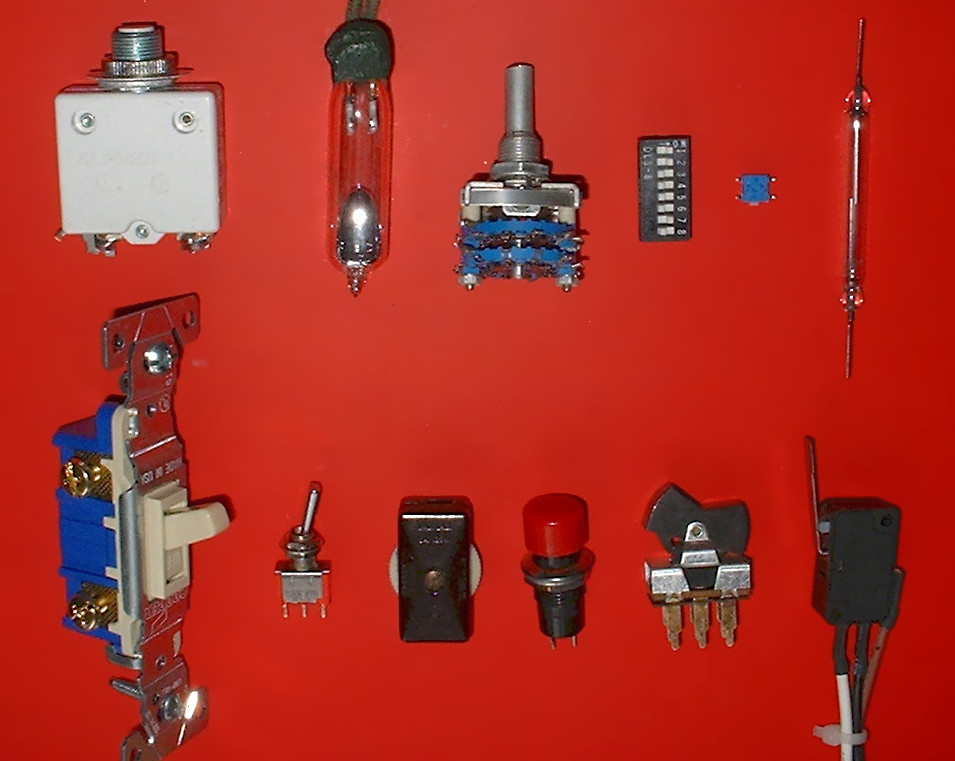
[edit]The moving part that applies the operating force to the contacts is called the actuator, and may be a toggle or dolly, a rocker, a push-button or any type of mechanical linkage (see photo).
Biased switches
[edit]A switch normally maintains its set position once operated. A biased switch contains a mechanism that springs it into another position when released by an operator. The momentary push-button switch is a type of biased switch. The most common type is a "push-to-make" (or normally-open or NO) switch, which makes contact when the button is pressed and breaks when the button is released. Each key of a computer keyboard, for example, is a normally-open "push-to-make" switch. A "push-to-break" (or normally closed or NC) switch, on the other hand, breaks contact when the button is pressed and makes contact when it is released. An example of a push-to-break switch is a button used to release a door held closed by an electromagnet. The interior lamp of a household refrigerator is controlled by a switch that is held open when the door is closed.
Rotary switch
[edit]
A rotary switch operates with a twisting motion of the operating handle with at least two positions. One or more positions of the switch may be momentary (biased with a spring), requiring the operator to hold the switch in the position. Other positions may have a detent to hold the position when released. A rotary switch may have multiple levels or "decks" in order to allow it to control multiple circuits.
One form of rotary switch consists of a spindle or "rotor" that has a contact arm or "spoke" which projects from its surface like a cam. It has an array of terminals, arranged in a circle around the rotor, each of which serves as a contact for the "spoke" through which any one of a number of different electrical circuits can be connected to the rotor. The switch is layered to allow the use of multiple poles, each layer is equivalent to one pole. Usually such a switch has a detent mechanism so it "clicks" from one active position to another rather than stalls in an intermediate position. Thus a rotary switch provides greater pole and throw capabilities than simpler switches do.
Other types use a cam mechanism to operate multiple independent sets of contacts.
Rotary switches were used as channel selectors on television receivers until the early 1970s, as range selectors on electrical metering equipment, as band selectors on multi-band radios and other similar purposes. In industry, rotary switches are used for control of measuring instruments, switchgear, or in control circuits. For example, a radio controlled overhead crane may have a large multi-circuit rotary switch to transfer hard-wired control signals from the local manual controls in the cab to the outputs of the remote control receiver.
Toggle switch
[edit]


A toggle switch or tumbler switch is a class of electrical switches that are manually actuated by a mechanical lever, handle, or rocking mechanism.
Toggle switches are available in many different styles and sizes, and are used in numerous applications. Many are designed to provide the simultaneous actuation of multiple sets of electrical contacts, or the control of large amounts of electric current or mains voltages.
The word "toggle" is a reference to a kind of mechanism or joint consisting of two arms, which are almost in line with each other, connected with an elbow-like pivot. However, the phrase "toggle switch" is applied to a switch with a short handle and a positive snap-action, whether it actually contains a toggle mechanism or not. Similarly, a switch where a definitive click is heard, is called a "positive on-off switch".[11] A very common use of this type of switch is to switch lights or other electrical equipment on or off. Multiple toggle switches may be mechanically interlocked to prevent forbidden combinations.
In some contexts, particularly computing, a toggle switch, or the action of toggling, is understood in the different sense of a mechanical or software switch that alternates between two states each time it is activated, regardless of mechanical construction. For example, the caps lock key on a computer causes all letters to be generated in capitals after it is pressed once; pressing it again reverts to lower-case letters.
Special types
[edit]
Switches can be designed to respond to any type of mechanical stimulus: for example, vibration (the trembler switch), tilt, air pressure, fluid level (a float switch), the turning of a key (key switch), linear or rotary movement (a limit switch or microswitch), or presence of a magnetic field (the reed switch). Many switches are operated automatically by changes in some environmental condition or by motion of machinery. A limit switch is used, for example, in machine tools to interlock operation with the proper position of tools. In heating or cooling systems a sail switch ensures that air flow is adequate in a duct. Pressure switches respond to fluid pressure.
Mercury tilt switch
[edit]The mercury switch consists of a drop of mercury inside a glass bulb with two or more contacts. The two contacts pass through the glass, and are connected by the mercury when the bulb is tilted to make the mercury roll on to them.
This type of switch performs much better than the ball tilt switch, as the liquid metal connection is unaffected by dirt, debris and oxidation, it wets the contacts ensuring a very low resistance bounce-free connection, and movement and vibration do not produce a poor contact. These types can be used for precision works.
It can also be used where arcing is dangerous (such as in the presence of explosive vapour) as the entire unit is sealed.
Knife switch
[edit]
Knife switches consist of a flat metal blade, hinged at one end, with an insulating handle for operation, and a fixed contact. When the switch is closed, current flows through the hinged pivot and blade and through the fixed contact. Such switches are usually not enclosed. The knife and contacts are typically formed of copper, steel, or brass, depending on the application. Fixed contacts may be backed up with a spring. Several parallel blades can be operated at the same time by one handle. The parts may be mounted on an insulating base with terminals for wiring, or may be directly bolted to an insulated switch board in a large assembly. Since the electrical contacts are exposed, the switch is used only where people cannot accidentally come in contact with the switch or where the voltage is so low as to not present a hazard.
Knife switches are made in many sizes from miniature switches to large devices used to carry thousands of amperes. In electrical transmission and distribution, gang-operated switches are used in circuits up to the highest voltages.
The disadvantages of the knife switch are the slow opening speed and the proximity of the operator to exposed live parts. Metal-enclosed safety disconnect switches are used for isolation of circuits in industrial power distribution. Sometimes spring-loaded auxiliary blades are fitted which momentarily carry the full current during opening, then quickly part to rapidly extinguish the arc.
Reversing switch
[edit]A DPDT switch has six connections, but since polarity reversal is a very common usage of DPDT switches, some variations of the DPDT switch are internally wired specifically for polarity reversal. These crossover switches only have four terminals rather than six. Two of the terminals are inputs and two are outputs. When connected to a battery or other DC source, the 4-way switch selects from either normal or reversed polarity. Such switches can also be used as intermediate switches in a multiway switching system for control of lamps by more than two switches.
Light switches
[edit]In building wiring, light switches are installed at convenient locations to control lighting and occasionally other circuits. By use of multiple-pole switches, multiway switching control of a lamp can be obtained from two or more places, such as the ends of a corridor or stairwell. A wireless light switch allows remote control of lamps for convenience; some lamps include a touch switch which electronically controls the lamp if touched anywhere. In public buildings several types of vandal resistant switches are used to prevent unauthorized use.
Slide switches
[edit]Slide switches are mechanical switches using a slider that moves (slides) from the open (off) position to the closed (on) position.
Electronic switches
[edit]The term switch has since spread to a variety of solid state electronics that perform a switching function, but which are controlled electronically by active devices rather than purely mechanically. These are categorized in the article electronic switch. Electromechanical switches (such as the traditional relay, electromechanical crossbar, and Strowger switch) bridge the categorization.
Other switches
[edit]- Centrifugal switch
- Company switch
- Crossbar switch
- Dead man's switch
- Fireman's switch
- Hall-effect switch
- Inertial switch
- Isolator switch
- Key switch
- Kill switch
- Latching switch
- Light switch
- Load control switch
- Membrane switch
- MEMS switch
- Optical switch
- Piezo switch
- Pull switch
- Push switch
- Sense switch
- Slotted optical switch
- Stepping switch
- Strowger switch
- Thermal switch
- Time switch
- Touch switch
- Transfer switch
- Zero speed switch
See also
[edit]Notes
[edit]- ^ The abbreviation N.C. (for "Normally closed") is also used to mean "Not connected" in the context of connector or part pins.
References
[edit]- ^ "Switch". The Free Dictionary. Farlex. 2008. Retrieved 2008-12-27.
- ^ "Switch". The American Heritage Dictionary, College Edition. Houghton Mifflin. 1979. p. 1301.
- ^ RF Switch Archived 2011-04-23 at the Wayback Machine Explanation by Herley – General Microwave
- ^ a b c "Engineer's Relay Handbook, 5th edition, Chapter 1.6 by RSIA (formerly NARM)". Archived from the original on 2017-07-05.
- ^ Walker, PMB, Chambers Science and Technology Dictionary, Edinburgh, 1988, ISBN 1-85296-150-3
- ^ Features of Technics E-33
- ^ "Lab Note #105 Contact Life – Unsuppressed vs. Suppressed Arcing" (PDF). Arc Suppression Technologies. April 2011. Archived from the original on December 3, 2013. Retrieved February 5, 2012. (3.6 Mb)
- ^ "Cornell Dubilier Capacitors – CDE (En-US)" (PDF). Archived (PDF) from the original on 2017-02-15. Retrieved 2017-10-05.
- ^ a b Fardo, Stephen; Patrick, Dale (2009-01-01). Electrical Power Systems Technology. The Fairmont Press, Inc. p. 337. ISBN 9780881735864. Archived from the original on 2017-12-24. Retrieved 2015-01-26.
- ^ Gregory K. McMillan (ed) Process/Industrial Instruments and Controls Handbook (5th Edition) (McGraw Hill, 1999) ISBN 0-07-012582-1 page 7.26
- ^ Gladstone, Bernard (1978). The New York Times complete manual of home repair. Times Books. p. 399. ISBN 9780812908923. Archived from the original on 2014-03-29.
External links
[edit] Media related to Electric switches at Wikimedia Commons

| International | |
|---|---|
| National | |
| Other | |
Switch
View on GrokipediaFundamentals
Definition and Basic Operation
An electrical switch is a device used to interrupt or redirect the flow of electrical current in a circuit, functioning as a binary component that either allows or blocks electron flow.[5] Switches operate on the principle of establishing or breaking continuity in a conductive path, enabling control over connected loads such as lights or motors.[6] In its basic operation, a switch in the open state (off position) interrupts the circuit, preventing current from flowing between its terminals. Conversely, in the closed state (on position), it completes the circuit, allowing current to pass through. Switches can be classified by action type: maintained switches retain their position after actuation, staying open or closed until manually changed, while momentary switches return to their default state (typically open) once the actuating force is removed.[7] This fundamental on-off behavior relies on mechanical or solid-state mechanisms to control circuit continuity.[8] A simple example is the single-pole single-throw (SPST) switch, which has one input terminal (pole) and one output terminal (throw), toggling a single circuit on or off. In a basic schematic diagram, the SPST switch is depicted as a straight line connecting the power source to the load when closed:Power Source ───[Closed SPST]─── Load ─── Ground
Power Source ───[Open SPST] Load ─── Ground
Power Source ───[Common]───[SPDT]─── NO ─── Load 1
                           └─── NC ─── Load 2
Historical Overview
The origins of electrical switches trace back to the 19th century, coinciding with the advent of practical electrical communication and power systems. In the 1830s, Samuel F. B. Morse developed the electrical telegraph, which relied on simple on-off mechanisms known as telegraph keys to transmit pulses of current representing Morse code.[14] These keys functioned as rudimentary manual switches, allowing operators to interrupt and restore electrical circuits over long distances via wire, marking one of the earliest applications of controlled electrical switching in technology.[15] Concurrently, knife switches emerged as a basic design for power distribution, consisting of a hinged metal blade that could be inserted into or withdrawn from fixed contacts to open or close circuits; this type became widespread in the late 1800s for controlling higher currents in early electrical installations.[16] By the late 19th and early 20th centuries, innovations addressed the limitations of these primitive designs, particularly in reliability and ease of use for expanding electrical applications. In telephony, rotary switches played a pivotal role starting in the 1890s, with Almon Brown Strowger inventing the first automatic telephone exchange system in 1891, which used rotating mechanisms to route calls without human operators, revolutionizing communication networks.[17] Around the same period, the Cutler-Hammer Manufacturing Company introduced early toggle switches circa 1900, featuring a lever that snapped between positions for more secure and intuitive operation in industrial and residential settings, laying groundwork for modern motor controls and lighting circuits.[18] These developments shifted switches from exposed, high-risk manual interventions to more enclosed and user-friendly forms, supporting the electrification boom. The mid-20th century brought a paradigm shift with the transition to electronic switching, driven by semiconductor advancements. In 1947, John Bardeen, Walter Brattain, and William Shockley at Bell Laboratories invented the point-contact transistor, a solid-state device capable of amplifying and switching electrical signals without the vacuum tubes' fragility, heat, or size issues, enabling compact and reliable electronic circuits.[19] This innovation paved the way for integrated circuits and digital logic, fundamentally altering switch design from mechanical to electronic paradigms. Building on this, the 1970s and 1980s saw the rise of membrane switches, first conceptualized in the early 1970s using conductive inks on flexible layers for silent, sealed interfaces in calculators and appliances, with commercial panels appearing by the early 1980s.[20] Similarly, capacitive touch switches gained traction in the 1970s, pioneered by engineers like Frank Beck and Bent Stumpe at CERN in 1973 for transparent, non-contact operation via changes in electrical capacitance, influencing user interfaces in consumer electronics.[21] Post-2010 advancements integrated switches into the Internet of Things (IoT) ecosystem, transforming them into networked, intelligent devices. The proliferation of wireless protocols like Zigbee and Z-Wave, alongside cloud connectivity, enabled smart switches to be remotely controlled via apps and automated based on sensors, with widespread adoption following the launch of voice assistants such as Amazon's Alexa in 2014.[22] Voice-activated models, compatible with platforms like Google Assistant and Apple HomeKit, allow hands-free operation through natural language processing, enhancing accessibility and energy efficiency in homes and buildings since the mid-2010s.[23]Mechanical Components
Contacts
Switch contacts are the metallic components within an electrical switch that physically connect or disconnect circuit paths to control current flow.[24] These contacts must exhibit high electrical conductivity, mechanical durability, and resistance to environmental degradation to ensure reliable operation across various applications.[25] Key terminology describes the structure and behavior of contacts. A pole refers to the number of independent circuits that a switch can control, with each pole corresponding to a separate set of contacts.[10] A throw indicates the number of distinct positions or terminals that each pole can connect to, determining the switch's versatility in routing signals.[10] Contacts are classified as normally open (NO) when they remain disconnected in the switch's rest position, allowing no current flow until actuated, or normally closed (NC) when they are connected by default and open upon actuation.[26] The terms make and break denote the actions of closing (making) or opening (breaking) the contact path, respectively, which are fundamental to the switch's operational sequence.[27] Contact configurations specify the arrangement of poles and throws, enabling diverse circuit functions. The single-pole single-throw (SPST) configuration features one pole and one throw, providing a simple on/off control for a single circuit with two terminals: one common and one that connects or disconnects based on actuation (e.g., NO for open at rest, NC for closed at rest).[10] In diagram form:SPST (NO): Terminal 1 ──[Open]── Terminal 2 (rest position)
Terminal 1 ──[Closed]─ Terminal 2 (actuated)
SPDT: Common ─┬─[NO Path 1]
              └─[NC Path 2] (rest: connected to NC)
DPDT: Common1 ─┬─[NO1]    Common2 ─┬─[NO2]
               └─[NC1]               └─[NC2]